Note: Descriptions are shown in the official language in which they were submitted.
CA 02858079 2014-06-03
WO 2013/085958
PCT/US2012/067882
APPARATUS AND DEVICES FOR PERCUTANEOUSLY EXTENDING
AN EXISTING SPINAL CONSTRUCT
Background
The present disclosure contemplates devices and instrumentation for extending
an
existing spinal construct, and more particularly to procedures for achieving
such extension
minimally invasively, and preferably percutaneously.
An emerging trend in spinal fixation is an increased incidence of adjacent
disc
degeneration subsequent to a previous fixation or fusion. This subsequent
degeneration often
requires fixation or fusion of additional levels of the spine. It is common in
current
techniques to expose the entire prior construct to access all of the existing
bone fasteners to
permit removal of the connecting member spanning the fasteners. The connecting
member is
removed and replaced with a longer member, such as a rod, to engage an
additional bone
fastener added at the new levels to be instrumented.
This exposure of the prior fixation construct disrupts the existing construct
complicating and lengthening the surgical procedure for adding the additional
level of
fixation. Such techniques are particularly problematic for a fixation
construct spanning three
or more vertebral levels. As such, there is a need for a device and method
that facilitates the
addition of further levels of fixation.
Several recent advancements have been disclosed that describe the extension of
existing spinal constructs with minimal disruption to the existing construct.
One example is
shown in co-pending commonly assigned U.S. Application No. 12/797,682,
entitled "Devices
and Methods for Adding an Additional Level of Fixation to an Existing
Construct", filed on
June 10, 2010 and published as No. 2010/0318131. Other examples include U.S.
Patent
7,976,567, entitled "Orthopedic Revision Connector", issued on July 12, 2011
to William B.
Null, et al. and U.S. Patent 8,021,399, entitled "Rod Extension for Extending
Fusion
Construct", issued on September 20, 2011 to Stephen Ritland. While these
approaches
represent improvements in revision techniques and devices, it would be
advantageous to not
only extend an existing construct in a relatively non-disruptive manner to
such construct, but
to do so in a minimally invasively and, preferably percutaneous procedure.
1
CA 02858079 2014-06-03
WO 2013/085958
PCT/US2012/067882
Summary
It is an object of the present invention to provide apparatus and devices for
adding an
additional construct to an existing spinal construct in a patient preferably
minimally
invasively and more preferably, percutaneously.
Description of the Figures
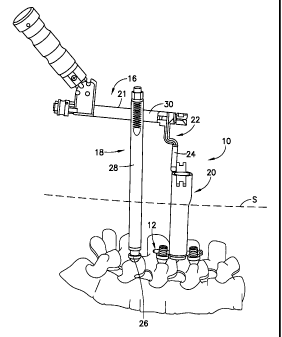
FIG. 1 is a side elevation view of a portion of a patient's spine showing
instrumentation disclosed herein to extend an existing ipsilateral spinal
construct.
FIG. 2 is an enlarged perspective view of the existing spinal construct and
inline
extension of FIG. 1.
FIG. 3 is a top plan view of the existing spinal construct and inline
extension of FIG.
1.
FIG. 4 is a top perspective view of a rod connector in accordance with one
arrangement of the disclosure for attachment to an existing spinal rod of the
existing spinal
construct shown in FIG. 1.
FIG. 5 is an exploded top perspective view of the rod connector of FIG. 4.
FIG. 6 is a longitudinal cross sectional view of the rod connector of FIG. 5.
FIG. 7 is a view of the rod connector of FIG. 6 showing the hook portion
having
been articulated to a different angular position.
FIG. 8 is a further top perspective view of the rod connector of FIG. 4
showing the
rod connector in an inline engagement with an existing spinal rod.
FIG. 9 is a top perspective exploded view of a rod connector extension
assembly
comprising a rod connector introducer and the rod connector of FIG. 4.
FIG. 10 is an enlarged side elevation view of the rod connector extension
assembly of
FIG. 9 showing details of the distal portion of the rod connector introducer
positioned for
releasable attachment to the rod connector.
FIG. 10a is a cross sectional view of FIG. 10 as seen along viewing lines X-X
of
FIG. 10.
2
CA 02858079 2014-06-03
WO 2013/085958
PCT/US2012/067882
FIG. 11 is a perspective view showing the assembled rod connector extension
assembly of FIG. 9 with an inner sleeve positioned for insertion into the rod
connector
introducer.
FIG. 12 is a further perspective view of the assembled rod connector extension
assembly of FIG. Ii with the inner sleeve received within the rod connector
introducer and a
hook rotator positioned for insertion into the inner sleeve.
FIG. 12a is an enlarged view of the distal end of the hook rotator as
encircled in FIG.
12.
FIG. 13 is a top perspective view of a portion of a patient's spine as viewed
in the
caudal direction showing the assembled rod connector extension assembly of
FIG. 12
disposed within an access port.
FIG. 14 is a top perspective view of FIG. 13 as viewed in the cephalad
direction.
FIG. 15 is a side elevation view of a patient's spine showing instrumentation
for
targeting the position of an existing spinal construct within a patient and an
additional spinal
implant extension assembly spaced therefrom.
FIG. 16 is a further view of FIG. 15 showing dilating instruments including an
access
port for use in a percutaneous procedure for extending an existing spinal
construct.
FIG. 17 is a further view of FIG. 16 with the dilating instruments removed and
the
access port positioned within the patient's spine adjacent the existing spinal
construct.
FIG. 18 is a side elevation view of the rod connector extension assembly
positioned
in the access port with the elongate additional rod of the rod connector being
oriented in a
first position generally parallel to the longitudinal axis of the access port.
FIG. 19 is a further view of FIG. 18 showing the rotation of the rod connector
introducer and the rod connector with the elongate additional rod being moved
subcutaneously toward the additional spinal implant extension assembly.
FIG. 20 is a further view of FIG. 19 showing further rotation of the rod
connector
introducer with the additional rod of the rod connector being introduced into
a slot of the
additional spinal implant extension assembly.
3
CA 02858079 2014-06-03
WO 2013/085958
PCT/US2012/067882
FIG. 21 is a further view of FIG. 20 showing final rotation of the rod
connector
introducer with the additional rod of the rod connector having been moved to a
second
different orientation transverse to the longitudinal axis of the access port
and the distal
portion of the additional rod extending through slots in the additional spinal
implant
extension assembly.
FIG. 22 is a view of FIG. 21 with the hook rotator and inner sleeve having
been
removed from the rod connector introducer and a driver instrument positioned
to introduce a
set screw through the additional spinal implant extension assembly for
securing the additional
rod of the rod connector to the additional spinal implant.
FIG. 23 is a view of FIG. 22 with the driver instrument removed and a driver
tool
positioned to introduce a set screw through the rod connector introducer for
securing the rod
connector to the existing spinal rod.
FIG. 24 is a posterior view of a portion of the patient's spine showing an
additional
construct extending an existing spinal construct to a further bony segment,
such as the ilium.
FIG. 25 is a top perspective view of a first alternative arrangement of a rod
connector
for attachment to an existing spinal rod of an existing spinal construct of
FIG 1.
FIG. 26 is a further view of the first alternative rod connector of FIG. 25
showing an
offset parallel connection of an additional rod to an existing spinal rod.
FIG. 27 is a top perspective view of the first alternative rod connector of
FIG. 25 in
assembly with a rod connector introducer and an additional elongate extension.
FIG. 28 is a top perspective view of a portion of a patient's spine showing an
oval
access port positioned adjacent an existing spinal rod for receipt of the rod
connector in the
assembly shown in FIG. 27.
FIG. 29 a top perspective view of a second alternative arrangement of a rod
connector
for attachment to an existing spinal rod of an existing spinal construct of
FIG 1.
FIG. 30 is a further view of the second alternative rod connector of FIG. 29
showing
an inline connection of an additional rod to an existing spinal rod.
4
CA 02858079 2014-06-03
WO 2013/085958
PCT/US2012/067882
Description of the Embodiments
For the purposes of promoting an understanding of the principles of the
invention,
reference will now be made to the embodiments illustrated in the drawings and
described in
the following written specification. It is understood that no limitation to
the scope of the
invention is thereby intended. It is further understood that the present
invention includes any
alterations and modifications to the illustrated embodiments and includes
further applications
of the principles of the invention as would normally occur to one skilled in
the art to which
this invention pertains.
Referring to FIGS. 1 and 2, an apparatus 10 is shown for extending an existing
spinal
construct 12 by adding an additional spinal construct 14 so as to increase the
level of spinal
fixation in a patient having previously undergone spinal fusion or other
spinal surgery. The
apparatus 10 generally comprises a rod connector extension assembly 16, a
spinal implant
extension assembly 18 and an access port 20. Rod connector extension assembly
16 includes
a rod connector introducer 21 and a rod connector 22 comprising an elongate
additional
spinal rod 24 serving as a connecting element, as will be described. Spinal
implant extension
assembly 18 comprises an additional spinal implant 26 and an elongate
extension 28
releas ably coupled thereto. As illustrated, the existing spinal construct 12
as well as the
additional spinal construct 14 are located ipsilaterly in the spine in this
particular
arrangement. As will be described in more detail below, rod connector
introducer 21
comprises an elongate extension 30 releasably attached to the rod connector
22. Each of
extension 28 and access port 20 is sized and of length to be accessible
outside the patient's
skin. The patient's skin or fascia is depicted as a phantom line S for
illustrative purposes
only, with the understanding that the level of the fascia relative to the
fixation location on the
spine will vary from patient to patient. Spinal construct 12 is an existing
spinal construct in
the sense that it has been installed prior to the installation of the
additional spinal construct 14
which means that existing spinal construct 12 may have been placed in a
previous surgical
procedure or may be placed during the same surgical procedure as, but prior
to, additional
spinal construct 14.
Turning to FIG. 2, further details of the additional spinal construct 14 and
the existing
spinal construct 12 are described. The existing spinal construct 12 comprises
at least two
previously implanted bone engaging implants 34 and 36 each of which is engaged
5
CA 02858079 2014-06-03
WO 2013/085958
PCT/US2012/067882
respectively to a corresponding vertebra 38 and 40. Implants 34 and 36 are
interconnected by
an existing spinal rod 42 extending ipsilaterally therebetween. Existing
spinal rod 42
includes an interconnecting portion 42a between implants 34 and 36 and an
extending portion
42b projecting outwardly beyond implant 34, although extending portion 42b may
also
project in the opposite direction beyond implant 36. As shown, each of
implants 34, 36 is a
polyaxial pedicle screw having a lower threaded fastener portion 44, 46 for
threaded
engagement respectively in a pedicle of vertebra 38 and a pedicle of vertebra
40. Each
implant 34, 36 includes a respective upper portion defining a yoke 48, 50 each
yoke having a
respective threaded slot 52, 54 for receipt of the existing spinal rod 42
therein. Set screws 55
and 57 respectively secure the existing spinal rod 42 to the implants 34 and
36.
The additional spinal construct 14 comprises rod connector 22 including
elongate
additional spinal rod 24, and a third bone engaging implant, namely additional
spinal implant
26. Spinal implant 26, as depicted in FIG. 2, is a polyaxial pedicle screw
having a lower
threaded portion 56 and an upper yoke portion 58 that articulates relative to
threaded portion
56. The threaded portion 56 is threadedly engaged to a third spinal segment 60
as will be
described. As depicted, spinal segment 60 is another vertebral body, it being
understood that
such spinal segment may be segment Si of the sacrum. The upper yoke portion 58
defines an
open ended threaded slot 62 for receipt and support therein of the distal free
end 24a of
additional spinal rod 24 and is fastened to the yoke portion 58 by a set screw
64 or other
suitable fastener. While additional spinal implant 26 is described as being a
pedicle screw, it
should be appreciated that depending upon the application additional spinal
implant 26 may
include other bone engaging implants with fasteners such as hooks, or rod
connectors.
Rod connector 22 comprises a lower first portion 66 and an upper second
portion 68
articulatingly attached to the first portion 66. The first portion 66 is
attached to the existing
spinal rod 42 as will be further described. The second portion 68 includes a
connecting
portion 70 projecting therefrom that in the arrangement described defines the
elongate
additional rod 24 terminating in distal free end 24a. As illustrated in FIGS.
2 and 3 the
additional spinal construct 14 is considered to be inline with the existing
spinal construct 12.
In such an arrangement, the upper second portion 68 of the rod connector 22 is
positioned
above and substantially in alignment with the axis of the existing spinal rod
42. The
connecting portion 70 has a first extent 71 and a second offset extent defined
by additional
6
CA 02858079 2014-06-03
WO 2013/085958
PCT/US2012/067882
rod 24 with a jog 72 therebetween. Extent 71 is positioned above bone engaging
implant 34
while the axis of additional spinal rod 24 is aligned generally parallel to
and colinear with the
axis of the existing spinal rod 42. As such, the existing spinal rod 42 and
the additional
spinal rod 24 are spaced approximately the same distance from a mid-line plane
through the
spine of a patient. It should be appreciated that depending upon the anatomy
of the patient
the orientation of the additional rod 24 relative to the existing rod 42 may
differ.
Turning now to FIGS. 4-8, further the details of the rod connector 22 are
described.
The lower end of the first portion 66 of rod connector 22 comprises a pair of
spaced hooks 74
and 76 each of which includes a respective projecting rod engagement member
74a and 76a.
Hooks 74 and 76 are spaced from each other at a distance defining an opening
78 that allows
the existing rod 42 to be received therebetween.
The first portion 66 of the rod connector 22 is attached to the second portion
68 by
ball insert 80 which allows the first portion 66 to rotate and articulate
relative to the second
portion 68, as will be described. The ball insert 80 comprises a truncated
sphere having a
first outer spherical surface 82 and a second outer cylindrical surface 84, as
shown in FIG 5.
The outer spherical surface 82 has a maximum diameter greater than the maximum
diameter
of the second outer cylindrical surface 84. The second portion 68 has an
interior spherical
surface 86 as shown in FIGS. 6 and 7 defining a socket for receipt of the
spherical surface 82
of the ball insert 80. Interior spherical surface of socket 86 has a diameter
slightly greater
than the maximum diameter of first outer spherical surface 82 of the ball
insert 80. The
socket 86 has an entrance opening 88 that has a diameter less than the
diameter of interior
spherical surface of socket 86 and slightly greater than the maximum diameter
of outer
cylindrical surface 84 of the ball insert 80. The ball insert 80 is inserted
through socket
opening 88 along an axis of the ball insert 80 defined by a longitudinal axis
of the outer
cylindrical surface 84. As such, the ball insert 80 will pass through the
socket opening 88
and into socket 86. Once therein, ball insert 80 is rotated 90 such that the
outer spherical
surface 82 is in sliding facing relationship with the interior spherical
surface of socket 86. In
this position, exterior threads 90 on an upper portion of the first portion 66
are threadably
engaged into interior threads 92 of the ball insert 80. The ball insert 80 may
be secured to the
threads 90 of the first portion 66 to prevent loosening by locking pins 94
which may be
installed through clearance openings 95 on opposite sides of first portion 68.
The structure
7
CA 02858079 2015-12-10
and operation of the ball insert 80 relative to socket 86 are fully described
in commonly
assigned U.S. Application No. 11/560,587, entitled "Multi-axial Spinal
Fixation System",
filed on November 16, 2006 and issued as U.S. Patent No. 8,162,990.
As described and as shown in FIGS. 6 and 7, the ball insert 80 and the joined
rod
connector first portion 66 can jointly articulate relative to the second
portion 68 about axis 96
defined by the centerline of opening 97 having interior threads 98 extending
into the second
portion 68 in communication with spherical socket 86. In addition, first
portion 66 can rotate
relative to second portion 68 about an axis of engagement 100 defined by the
centerline of
exterior threads 90 of the first portion 66. In FIG. 6 the axis of engagement
100 and axis 96
of the second portion 68 are linearly aligned, while in FIG. 7, for example,
the axis of
engagement 100 is disposed at an angle with respect to axis 96 with first
portion 66 having
been articulated relative to second portion 68. In the position shown in FIG.
7, the first
portion 66 is in an unlocked position and may still rotate about axis of
engagement 100 so as
to cause hooks 74 and 76 to engage existing rod 42, allowing greater
flexibility for the
attachment of the rod connector 22 to the existing rod 42.
Referring to FIGS. 5 and 6 a device for rotating the first portion 66 relative
to the
second portion 68 as well as for providing a provisional retention of the rod
connector 22 to
an existing rod 42 is described. A rotation element 102 supported by the first
portion 66
comprises a rotation pin 104, a wave spring 106 and a retention ring 108. The
rotation pin
104 comprises a head104a having an internal hex socket 104b for receipt of the
hook rotator,
as will be described. Socket 104b may comprise other suitable socket
configurations, such as
a conventional Torx configuration. Rotation pin 104 further comprises a shank
104c having
an upper outer hex surface 104d a distal outer cylindrical surface 104e and a
larger
intermediate cylindrical surface 104f between surfaces 104d and 104e. Surfaces
104d, 104e
and 104f may also include other suitable configurations.
To assemble the rotation element 102 to the rod connector 22, the rotation pin
104 is
inserted into opening 97 along axis 96 through threads 98 and into opening 110
interiorly of
threads 90 of first portion 66. The interior surface 112 of opening 110
comprises a
complementary hex configuration for matable receipt of the hex surface 104d of
rotation pin
104. With such hex surfaces in engagement, rotation of the rotation pin 104
will cause
8
CA 02858079 2014-06-03
WO 2013/085958
PCT/US2012/067882
rotation of the first portion 66. Wave spring 106 is placed over intermediate
cylindrical
surface 104f and retention ring 108 is placed over distal cylindrical surface
104e. Retention
ring 108 is secured to distal cylindrical surface 104e by laser welding or
other conventional
joining techniques. Securement of the retention ring 108 to the rotation pin
104 compresses
the wave spring 106 between the retention ring 108 and an inner surface 114
adjacent, and
substantially orthogonal, to interior surface 112 of opening 110 in the first
portion 66. As
such, rotation element 102 is movably supported on said first portion 66 by
wave spring 106
with the distal end of the retention ring108 defining a rod engagement surface
108a normally
biased into the opening 78 between the hooks 74 and 76 of the first portion
66. Such biased
interference of the rod engagement surface 108a into opening 78 allows the
existing rod 42 to
be received into opening 78 and provisionally held by the rod engagement
members 74a and
76a upon rotation of the hooks 74 and 76 under the bias of wave spring 106 as
shown in FIG
8. It should be appreciated that other spring elements, such as a helical
spring, may be used
as alternatives to wave spring 106.
While the rod connector 22 is provisionally retained to the existing rod 42 by
the rod
engagement members 74a and 76a under the bias of wave spring 106, this
position is an
unlocked position with rotation element 102 serving as a provisional holding
element. A
device for locking the rod connector 22 in a locked position relative to the
existing rod 42 is
described with further reference to FIGS. 5 and 6. A locking element such as a
set screw 116
has exterior threads 116a for threadable rotational engagement with interior
threads 98
extending within the second portion 68. The upper proximal end of the set
screw 116
comprises a suitable socket, such as a Torx hexalobe socket 116b for receipt
of a suitable tool
for inserting and rotating set screw 116. The lower distal surface 116c is
configured to
engage the upper surface of head 104a of rotation pin 104 during rotational
insertion.
Continued insertion and tightening of the set screw 116 into threads 98 will
cause the rod
engagement surface 108a at the lower end of the rotation element 102 to
forcibly engage the
existing rod 42, effectively relieving the bias of wave spring 106 to thereby
lock the first
portion 66 to the existing rod 42. The force against the existing rod 42 also
causes the first
portion 66 and thereby the ball insert 80 to move downwardly relative to
second portion 68
forcing the outer spherical surface 82 at the lower half of ball insert 80
tightly against interior
9
CA 02858079 2014-06-03
WO 2013/085958
PCT/US2012/067882
spherical surface of socket 86 of second portion 68, thereby locking first
portion 66 and
second portion 68 securely together.
Referring still to FIGS. 4 through 7 further details of the rod connector 22
are
described. Projecting outwardly from second portion 68 is a connecting element
70. In this
arrangement, connecting element 70 includes first extent 71 and elongated
additional rod 24
terminating in distal end 24a. Connecting element 70 includes a jog 72 between
first extent
71 and additional rod 24 causing the additional rod 24 to be offset relative
to the first extent
71 so as to accommodate spinal anatomy. It should be appreciated that the
height of jog 72
may be varied to provide different offset dimensions between additional rod 24
and first
extent 71. In some arrangements, jog 72 may be eliminated such that first
extent 71 is
colinear with additional rod 24. In addition, first extent 71 and/or
additional rod 24 may be
curved so as to accommodate different spinal anatomical conditions. In the
arrangement
shown, additional spinal rod 24 defines a longitudinal axis 24b that extends
transverse to axis
96 of the second portion 68 of rod connector 22. In one application, for
example, axis 24b
may be disposed at an angle of approximately 90 with respect to axis 96,
shown in FIGS. 5
and 6. In the arrangement shown, rod connector 22 is formed as a one-piece
structure.
Connecting element 70 including elongated additional rod 24 may be otherwise
integrally
attached to second portion 68 by any suitable fastening means, including
without limitation,
welding, brazing and screws.
Turning now to FIGS. 9-12, details of the free hand rod connector introducer
21 are
described. Rod connector introducer 21 comprises an elongate hollow extension
30 and a
handle 118 interconnected to extension by an offset bracket 120. Handle 118
may be
selectively moved to different angular orientations by releasing and
interlocking projection
122 into multiple grooves 120a, 120b and 120c in bracket 120. Three positions
are shown,
namely 0 , 45 and 90 with handle 118 being in the 0 position shown in FIG.
9 and in the
45 position as shown in FIG. 12. Other angular orientations may also be
provided. Hollow
extension 30 comprises an elongate outer sleeve 124 having a proximal end 124a
and a distal
end 124b with a lumen 124c extending fully longitudinally therethrough.
Proximal end 124a
is suitably attached to bracket 120 and distal end 124b is configured to
secure releasably to
the second portion 68 of the rod connector 22.
CA 02858079 2014-06-03
WO 2013/085958
PCT/US2012/067882
As illustrated in further detail in FIG.10, the rod connector securement
structure at
the distal end 124b of sleeve 124 comprises a projecting attachment pin 126
and a skirt
member 128 disposed diametrically opposite pin 126. Attachment pin 126 is of
generally
oval shaped configuration and comprises a flexible latch 126a projecting from
a side surface
of pin 126. Skirt member 128 projects axially downwardly from distal end 124b
and has a
concave inner surface configured to correspond to the outer curved surface 68a
at one end of
second portion 68. Attachment pin 126 is configured to be received in a
complementary oval
shaped hole 130 formed in an upper surface of second portion 68 of rod
connector 22 (see
FIGS. 7-8) with flexible latch 126a being releasably attached to a ledge 130a
formed in a
side wall of hole 130 in a snap-fit manner as shown in FIG.10a. With
attachment pin 126
received in hole 130 and skirt member 128 extending in close proximity around
a portion of
curved surface 68a, the outer sleeve 124 is substantially prevented from
rotating relative to
both the second portion 68 of rod connector 22 and elongate additional rod 24
which is
integral with second portion 68. While attachment pin 126 and skirt member 128
are
effective in releasably securing the outer sleeve 124 to the rod connector
second portion 68, it
should be appreciated that other releasable securement structure, such as
screw threads, may
be used.
Referring now to FIG.11, rod connector introducer 21 is shown preliminarily
attached
to rod connector 22. To provide a more secure attachment, an inner elongate
hollow sleeve
134 is included. Inner sleeve 134 has a proximal end 134a and a distal end
with a lumen
134c extending fully longitudinally therethrough. Proximal end 134a terminates
in a flange
134d having a hex surface for engagement with a wrench or other suitable tool.
Distal end
134b comprises external threads 134e for threadable attachment with the
interior threads 98
in the second portion 68 of rod connector 22. After outer sleeve 124 is
preliminarily attached
to rod connector 22, inner sleeve 134 is inserted through lumen 124c of sleeve
124 with
threads 134e of the inner sleeve threadably engaging threads 98 in the second
portion 68 of
rod connector 22. Continued tightening of inner sleeve 134 causes flange 134d
to engage an
upper surface of distal end 124a of outer sleeve 124 thereby compressing the
outer sleeve 124
between flange 134d and rod connector 22 for secure attachment thereto.
With extension 30 suitably releasably secured to rod connector 22, a hook
rotator
136is inserted into the lumen 134c in the inner sleeve 134, as shown in FIG.
12 to complete
11
CA 02858079 2014-06-03
WO 2013/085958
PCT/US2012/067882
the rod connector extension assembly 16. Hook rotator 136 comprises an
elongate shaft 136a
having a proximal end 136b and a distal end 136c. Proximal end 136b includes a
tool
attachment surface 136d having a hex or other suitable configuration for
engagement with a
hand wrench 135 (see FIG. 21). Distal end 136c comprises an engagement surface
136e
having a complementary mating configuration, such as hex configuration, for
engagement
with the socket 104b of rotation pin 104. As described above with reference to
FIG. 5
rotation of the rotation pin 104 causes rotation of rod connector first
portion 66 and hooks 74
and 76 projecting therefrom.
Hook rotator 136 includes at its proximal end a connection portion 136f and a
ring
136g. Ring 136g is pinned to connection portion 136f to prevent relative
rotation
therebetween but is spring biased to allow axial translation when ring 136g is
depressed
distally. Ring 136g includes an internal hex surface that engages the hex
surface of the tool
attachment surface 136d when ring 136g is biased normally upwardly, thus
preventing
rotation. When ring 136g is depressed distally downwardly by a suitable tool
such as by
hand wrench 135, the internal hex surface of ring 136g disengages from the
external hex
surface of tool attachment surface 136d, thereby allowing rotation of the
shaft 136a relative
to connection portion 136f. Such disengagement allows the tool attachment
surface 136d to
engage a complementary hex surface (not shown) within the hand wrench 135 such
that
rotation of the hand wrench 135 rotates the elongate shaft 136a. Upon rotation
of the shaft
136a by hand wrench 135 from outside the patient, the first portion 66 of the
rod connector
22 and thereby hooks 74 and 76 are also rotated in a manner to effect
connection of the rod
connector 22 to existing rod 42, as will be described.
As hook rotator 136 is inserted into the lumen 134c of inner sleeve 134
engagement
surface 136e is properly seated within the socket 104b of rotation pin 104. If
proper seating
is not achieved a marker or other suitable indicator may extend from the
proximal end of
elongate shaft 136a to inform the surgeon that engagement surface 136e is not
properly
inserted into socket 104b. The first portion 66 with hooks 74 and 76 may be
rotated manually
until proper seating is achieved. Upon such proper seating, connection portion
136f of hook
rotator 136 is releasably attached to the bracket 120 at bracket portion 120d
by a flexible
portion 136h, as shown in FIG. 12 to hold connection portion 136f fixed
relative to extension
30. As such, rotation of elongate shaft 136a relative to connection portion
136f also rotates
12
CA 02858079 2014-06-03
WO 2013/085958
PCT/US2012/067882
shaft 136a relative to extension 30 and the rod connector 22 attached thereto.
With the rod
connector extension assembly 16 thus being assembled, longitudinal axis 24b of
the elongate
additional rod 24 projects outwardly from extension 30 and transverse to axis
96 of the
second connector portion 68. In the arrangement shown, the angle between
longitudinal axis
24b and axis 96 is substantially 90 . While a 90 angle is suitable, it should
be appreciated
that other angles may be contemplated.
In a preferred arrangement of rod connector extension assembly 16, hook
rotator 136
is formed at its distal tip 136i as illustrated in FIG. 12a to have a curved
configuration
defining a ball hex shape. Thus, while the complementary mating configuration
of
engagement surface 136e is constructed to engage socket 104b and substantially
prevents
rotation unless shaft 136a is rotated, the ball hex shape will allow some
articulation of the rod
connector first portion 66 relative to second portion 68, as illustrated in
FIG. 7, even when
engagement surface 136e is seated within the socket 104b of rotation pin 104.
With the rod
connector first portion 66 being disposed at an angle with respect to rod
connector second
portion 68, first portion 66 may still be rotated about axis of engagement 100
by hook rotator
136. It should be understood that the distal tip 136i of rotator hook 136 may
also be formed
to be relatively flat such that when the complementary mating configuration of
engagement
surface 136e engages socket 104b there will be substantially no articulation
of the first
portion 66, with such first portion 66 being held generally fixed relative to
the rod connector
introducer 21 by the hook rotator 136.
Turning now to FIGS. 13-14, details of the access port 20 are described.
Access port
20 comprises an elongate sleeve 20a having a proximal end 20b and a distal end
20c for
placement into the patient adjacent the existing spinal construct 12. The
access port 20 is of
length such that the proximal end 20b projects out from the patient's skin S
when the distal
end 20c is positioned adjacent existing construct 12. Sleeve 20a includes a
perimetric
sidewall 20d and a lumen 20e extending lengthwise therethrough. Lumen 20e is
sized to
receive the rod connector introducer 21 with the rod connector 22 secured
thereto for
attachment of the rod connector 22 to the existing spinal rod 42. Sleeve 20a
has a slot 20f
extending axially for a length through the sidewall 20d such that the slot 20f
extends outside
the patient when the distal end of the access port 20 is positioned adjacent
existing construct
12. In the arrangement shown, slot 20f is arranged to face the additional
spinal implant 26 to
13
CA 02858079 2014-06-03
WO 2013/085958
PCT/US2012/067882
be implanted and extends axially fully through both the proximal end 20b and
the distal end
20c. Slot 20f is sized and configured to receive therethrough the rod
connector introducer
21and the connecting portion 70 of rod connector 22 with the elongate
additional rod 24
projecting therefrom. Slot 20g is formed diametrically opposite slot 20f, as
shown in FIG.
14, slot 20g extending through distal end 20c and extending axially through
perimetric
sidewall 20d for a length that extends outside skin S of the patient. Slot 20g
is sized and
configured to receive therethrough at least a portion of the rod connector 22
and rod
connector introducer 21 to accommodate rotation of the rod connector
introducer 21, as will
be described. A bracket 138 may be utilized to fix the access port 20 to an
operating table in
a conventional manner so as to maintain the access port 20 in place throughout
the surgical
procedure. While access port 20 is described in this arrangement as being
generally tubular,
it should be appreciated that access port may include other suitable
structures such as by a
pair of opposed blades defining a lumen therebetween, wherein the blades may
be coupled at
their proximal ends by a suitable ring or other coupling member.
Having described the devices and instruments for extending an existing spinal
rod
construct in a patient, the procedures for such extension are now described
with particular
reference to FIGS. 15-23. The first procedure relates to percutaneously
extending an existing
spinal construct 12 as shown in FIG. 15 with an inline ipsilateral additional
construct 14 as
described above. The engagement of the additional spinal implant 26 as a
component of the
additional spinal rod construct 14 is described. Spinal implant extension
assembly 18
comprises an elongate extension 28 which includes a hollow sleeve 140
releasably secured to
the additional spinal implant 26. Spinal implant 26 is described as noted
above with
reference to FIG.2 as being a polyaxial pedicle screw in this arrangement.
Sleeve 140 has a
pair of opposing slots 142 extending axially through the sleeve diametrically
apart. The slots
142 are aligned and in communication with the slot 62 in the upper yoke
portion 58 (see FIG.
2) of the spinal implant 26. The additional spinal implant 26 is
percutaneously attached to
the pedicle of the third spinal segment 60, which may be a segment of the
sacrum 51 or
another vertebral body. Additional spinal implant 26 is introduced through a
small
percutaneous incision 144 made through the skin S of the patient. The incision
144 is
approximately 10-30 mm in length. The dilation of incision 144 and the
percutaneous
attachment of spinal implant 26 to a spinal segment such as vertebral body 60
is fully
14
CA 02858079 2015-12-10
described in commonly assigned U.S. Patent Application No. 12/818,965,
entitled "System
for Percutaneously Fixing a Connecting Rod to a Spine", filed on June 18,
2010, and issued
as U.S. Patent No. 8,142,437, (the '437 Patent). Once spinal implant 26 is
attached to the
vertebral body 60, the sleeve 140 as well as slots 142 project out from the
patient through
dilated incision 144 with the slots 142 being rotatably manipulable upon
rotation of sleeve
140 to be aligned with slot 20f of access port 20 as will be described with
reference to FIG.
16.
Using fluoroscopy or other suitable imaging techniques, the existing spinal
rod 42 is
initially targeted so as to establish the position of the existing rod 42 in
the patient. In this
instance, the interconnecting portion 42a of existing rod 42 is targeted
rather than extending
portion 42b projecting outwardly beyond implant 34. A small percutaneous
incision 146 is
made through the skin S of the patient, the incision 146 being approximately
10-30 mm in
length, although other suitable dimensions may be used. A targeting rod 148 is
placed
through the incised puncture and pushed through the tissue of the patient down
to the existing
spinal rod 42. Once the access path has been created and the position of the
existing rod 42
established a series of sequentially increasing dilating instruments are
inserted over the
targeting rod 148. As depicted in FIG. 16, the dilating instruments include
dilating cannulas
150, 152 and 154 of increasing diameter. The number of dilating cannulas may
vary
depending upon the procedure and the desired extent the incision 146 is to be
expanded upon
dilation. In addition, the dilating cannulas may include features that
maintain the lateral
position of such cannulas relative to existing rod 42 during insertion. Access
port 20 is then
finally placed over the last dilating cannula 154 with the opposing slots 20f
and 20g
communicating with existing rod 42 such that the distal end 20c of access port
20 straddles
but does not attach to existing rod 42, as shown in FIG. 16. The dilating
instruments are then
removed as illustrated in FIG. 17 leaving the access port 20 in place. The
central
longitudinal axis of the access port 20 is generally aligned with and
perpendicular to the
longitudinal axis of existing rod 40. Bracket 138 may be utilized to fix the
access port 20 to
the operating table so as to maintain access port 20 fixed in place throughout
the surgical
procedure. The proximal end 20b of the access port 20 as well as slot 20f
project out from
the patient's skin, S, with access port slot 20f being generally aligned with
and in facing
relation to slots 142 of sleeve 140 in spinal implant extension assembly 18.
Although also
CA 02858079 2014-06-03
WO 2013/085958
PCT/US2012/067882
shown as extending outwardly of the patient's skin, S, slot 20g may be of
length to lie below
the patient's skin, S.
By reference to FIG. 18 as well as to FIG. 1, the introduction of the rod
connector 22
through manipulation of the rod connector extension assembly 16 is explained.
The handle
118 may be in the 45 position for this stage of the procedure. With access
port 20 fixed in
place a surgeon grasps handle 118 and initially orients the extension 30 of
rod connector
introducer 21 generally parallel to the spine of the patient such that the
axis 24b elongate
additional rod 24 is oriented in a first position generally parallel to the
longitudinal axis of
access port 20. In this position, the additional rod 24 is within the lumen
20e of access port
with the connecting portion 70 of rod connector 22 extending through and
projecting
15 outwardly from slot 20f of access port 20. Through manipulation of rod
connector introducer
21 the additional rod 24 is moved in this first orientation until the rod
connector 22 is below
the skin S of the patient. At this point, the rod connector introducer 21,
with the access port
slot 20f serving as a guide, is rotated so that additional rod 24 is rotated
clockwise as viewed
in FIG. 19 in a direction indicated by arrow, R.from its first orientation out
from access slot
20 20f and toward sleeve 140 of spinal implant extension assembly 18.
During such movement,
the distal end 24a of additional rod 24 is subcutaneously moved through tissue
of the patient
beneath the skin S of the patient toward the sleeve 140 of spinal implant
extension assembly
18.
Continued rotation of handle 118 in the direction R further rotates rod
connector
introducer 21 until the distal end 24a of additional rod 24 approximates
sleeve 140. With
fluoroscopy the distal end 24a of additional rod 24 is guided into slot 142
that is in facing
relationship with access port slot 20f, as shown in FIG. 20 for ultimate
reduction into slot 62
of additional spinal implant 26. It should be appreciated that the additional
rod distal end 24a
may be directly received within slot 62 of additional spinal implant 26.
During this portion
of the rotation of rod connector introducer 21, the rod connector 22 as well
as the distal end
124b of the rod connector introducer extension 30 may project outwardly from
the opposite
access port slot 20g to accommodate the rotation of rod connector introducer
21.
Upon final rotation of rod connector introducer 21 by handle 118 as shown in
FIG. 21
the distal end 24a of additional rod 24 extends through both slots 142 of
sleeve 140 and is
either situated in slot 62 of additional spinal implant 26(FIG. 2) or closely
thereto. In this
16
CA 02858079 2014-06-03
WO 2013/085958
PCT/US2012/067882
position the additional rod 24 has been moved to a second different
orientation such that the
axis 24b is transverse, and substantially perpendicular, to the longitudinal
axis of access port
20. Also with the aid of fluoroscopy, the rod connector 22 at this point
receives the existing
spinal rod 42 within the opening 78 between hooks 74 and 76 of rod connector
first portion
66. As described above, with first portion 66 capable of articulating while
being held against
rotation by the hook rotator 136, proper receipt of existing spinal rod 42
within opening 78 is
achieved even if the longitudinal axis of rod connector introducer 21 is not
precisely
perpendicular to the axis of existing rod 42 thus allowing for potential
irregularities of the
spine. In this position, existing spinal rod 42 is in an unlocked position
with respect to rod
connector 22. Prior to rotation of rod connector hooks 74 and 76 to engage
existing rod 42
for locking, the surgeon may, if necessary, reduce the additional rod 24 into
slot 62 of
additional spinal implant 26. Such reduction may be achieved by connecting a
rod persuader
(not shown) to a rod persuader coupling member 156 disposed at the proximal
and of sleeve
140. The rod persuader including its structure and cooperation with rod
persuader coupling
member 156 is fully described in the '437 Patent, the disclosure of which is
incorporated
herein by reference in its entirety.
With continued reference to FIG. 21 as well as to FIGS. 5- 6, the engagement
of the
rod connector 22 to the existing spinal rod 42 is described. Hand wrench 135
is used to
suitably depress ring 136g for attachment to tool attachment surface 136d as
described above
and is rotated either by hand or an appropriate tool. Rotation of wrench 135
rotates hook
rotator shaft 136a as well as engagement surface 136e which is engaged within
socket 104b
of rotation pin 104. Upon such rotation of the shaft 136a, the rotation pin
104 rotates the first
portion 66 of the rod connector 22 about the axis of engagement 100 in a
manner to facilitate
alignment of opening 78 relative to existing rod 42. Hooks 74 and 76 and the
respective rod
engagement member 74a and 76a are then rotated in a manner to engage the
existing rod 42.
As the hooks 74 and 76 are rotated, the engagement surface 108a at the distal
end of rotation
element 102 engages the existing rod 42 under the bias of wave spring 106
pushing the head
104a of the rotation pin 104 slightly upwardly into opening 97 of first
portion 66. During
such rotation the existing rod 42 is thereby received between the rod
engagement member
74a and 76a and rotation pin engagement surface 108a in a snap-fitting
movement that
provides a tactile and potentially an audio indication to the surgeon that the
existing rod 42 is
17
CA 02858079 2014-06-03
WO 2013/085958
PCT/US2012/067882
properly seated in the rod connector 22 in a provisional engagement whereby
the rod
connector 22 is held on but not locked to the existing rod 42. Rod connector
first portion 66
is rotated approximately 60 with respect to second portion 68 to establish
such provisional
engagement. It should be understood that first portion 66 may be rotated
relative to second
portion 68 at other angles which may be less than 60 or up to approximately
90 .
Once the rod connector 22 has been rotated to the provisional engagement
position,
the distal end 24a of additional rod 24 may then be secured to additional
spinal implant 26 as
described with reference to FIG. 22. Set screw 64 is suitably attached to a
driver instrument
158 and sized and configured to introduce the set screw 64 with instrument 158
attached
thereto into and through hollow sleeve 140 until set screw 64 engages the
threads in the slot
62 of the upper yoke portion 58. Set screw 64 is tightened by rotation of
instrument 158 to
secure the additional rod 24 to the additional spinal implant 26. Instrument
158 is then
detached from set screw 64 and removed from sleeve 140.
Turning now to FIG. 23 as well as to FIGS. 5- 6 and 11, locking of the rod
connector
22 to additional rod 42 is described. After removing hook rotator 136 and
inner sleeve 134
from rod connector introducer 21, set screw 116 is suitably attached to a
driver tool 160 with
the distal tip of tool 160 in engagement with socket 116b of set screw 116.
Tool 160 with set
screw 116 attached thereto is sized and configured to be received within lumen
124c of outer
sleeve 124 of rod connector introducer 21 until set screw 116 engages the
threads 98 in rod
connector second portion 68. As noted above, the lower distal surface 116c of
set screw 116
engages the upper surface of head 104a of rotation pin 104 during rotational
insertion of set
screw 116. Continued insertion and tightening of the set screw 116 into
threads 98 will push
the rotation pin 104 downwardly causing the rod engagement surface 108a at the
lower end
of the rotation element 102 to forcibly engage the existing rod 42. The force
against the
existing rod 42 also causes the first portion 66 and thereby the ball insert
80 to move
downwardly relative to second portion 68 forcing the outer spherical surface
82 of ball insert
80 tightly against interior spherical surface of socket 86 of second portion
68, thereby locking
first portion 66 and second portion 68 securely together.
With rod connector 22 properly secured to existing spinal rod 42, tool 160 is
detached
from set screw 116 and removed from rod connector introducer 21. Spinal
implant extension
assembly 18, rod connector introducer 21 and access port 20 are also then
removed from the
18
CA 02858079 2014-06-03
WO 2013/085958
PCT/US2012/067882
patient. To facilitate removal of rod connector introducer 21 from rod
connector 22, handle
118 may be adjustably moved to a position generally parallel to the
longitudinal axis of outer
sleeve 124 as shown, for example in FIG. 9. With the removal of the
instruments the inline
ipsilateral extension of the existing spinal construct 12 by additional spinal
construct 14 as
shown in FIG. 2 is complete and the incisions 144 and 146 maybe appropriately
sutured. In
the percutaneous procedure described, the rod connector 22 is inserted through
the access
port 20 and rotated for attachment to the existing rod 42 in a top loading
procedure without
disturbing the existing implants 34 and 36 or the previous connections to the
existing rod 42.
Such top loading allows a surgeon to insert the rod connector 22 by
manipulating the rod
connector by rotation and connect it to the existing rod 42 from above the
spine facilitating
the percutaneous procedure.
In the procedure just described, rod connector 22 is attached to existing
spinal rod 42
by targeting the interconnecting extent 42a between two existing bone engaging
implants 34
and 36, each of which is engaged respectively to a corresponding vertebra 38
and 40. The
elongate additional rod 24 projecting from rod connector 22 may be attached to
additional
spinal implant 26 in either the caudal or cephalad direction. Using the same
technique
described herein, it should be understood that rod connector 22 may also be
used to attach an
existing spinal construct to other bony segments, not only within the spine,
such as vertebral
bodies or the sacrum, but outside the spine, such as the ilium. Such an
arrangement is
contemplated, for example as shown in FIG. 24 where bone engaging implant 36
is attached
to vertebral body L5 and bone engaging implant 34 is attached to segment Si of
the sacrum
and these implants are interconnected by existing spinal rod 42 with extending
portion 42b
projecting in the caudal direction. With extending portion 42b having
sufficient extent,
extending portion 42b may be targeted for receipt of and connection to rod
connector 22, as
described above. A third bone engaging implant 162 such as an iliac screw
similar to spinal
implant 26 may be percutaneously secured to the ilium through a separate
spaced incision
with a releasable bone implant extension assembly similar to spinal implant
extension
assembly 18, as described in the '437 Patent. Rod connector 22 may then be
inserted with
additional rod 24 passed subcutaneously from existing rod 42 to the iliac
screw 162 in a
manner as described hereinabove to form the additional construct extending
from segment Si
19
CA 02858079 2014-06-03
WO 2013/085958
PCT/US2012/067882
of the sacrum to the ilium. Rod connector 22 may be configured with or without
jog 72 and
curved if desired to accommodate the anatomical conditions.
Having described a particular arrangement of rod connector 22 wherein
additional rod
24 is integrally attached thereto, two alternative arrangements are described
wherein a rod
connector is configured to receive an additional rod rather than such
additional rod being
integrally attached. The first alternative arrangement is shown and described
with reference
to FIGS. 25 and 26. Rod connector 200 comprises a first portion 66
articulatingly attached to
a second portion 68, first portion 66 and second portion 68 having structure
identical to first
and second portions 66 and 68 respectively of rod connector 22. Rod connector
200 further
includes a connecting portion 202 projecting outwardly from second portion 68
and
terminating in an additional rod support 204. Support 204 comprises a yoke 206
having a
pair of opposing upstanding arms 206a and 206b defining an open ended slot 208
having
internal threads 210. The slot 208 is sized and configured to receive and
support therein an
additional spinal rod 212 which is fastened to the yoke 206 by a set screw 214
or other
suitable fastener. As shown in FIG. 26, rod connector 200 is configured to be
attached to the
existing spinal rod, such as rod 42 and to receive and support additional rod
212 in an
orientation that may be generally parallel to existing rod 42. As such, the
axis of additional
rod 212 is laterally offset with respect to the axis of existing rod 42. It
should be appreciated
that depending upon the anatomy of the patient the orientation of the
additional rod 212
relative to the existing rod 42 may not necessarily be parallel.
By reference to FIGS. 27 and 28 a minimally invasive technique for attaching
rod
connector 200 to a spinal rod in an existing spinal construct is described. A
rod connector
introducer 21 as described above may be releasably attached to second portion
68 of rod
connector 200. An elongate extension 28 as described above with respect to
spinal implant
extension assembly 18 includes a hollow sleeve 140 that is releas ably secured
to the
additional rod support 204 in the same manner as attached to additional spinal
implant 26.
To attach rod connector 200 to existing spinal rod such as rod 42, either the
interconnecting
portion 42a between two existing bone implants or the extending portion 42b
projecting
beyond one of the two existing bone implants may be targeted for attachment.
FIG. 28
illustrates the targeting of the interconnecting portion 42a for connection.
Using fluoroscopy
or other suitable imaging techniques as described above, a small incision 216
is initially
CA 02858079 2014-06-03
WO 2013/085958
PCT/US2012/067882
formed through the skin S. The incision 216 is enlarged radially and laterally
with a series of
sequentially increasing dilating instruments with the ultimate insertion of an
oval access port
218. Oval access port 218 is sized and configured to receive the assembly 220
comprising
rod connector 200, rod connector introducer 21 and the elongate extension 28.
A hook
rotator, such as hook rotator 136, may be inserted through rod connector
introducer 21 to
engage the rotation element 104 in rod connector 200 so as to restrain the
hooks 74 and 76
from rotation, as set forth above. The assembly 220 is introduced into oval
access port 216
with the rod connector 200 in an orientation that is maintained beneath the
skin until the
interconnecting portion 42a of existing spinal rod 42 is received within the
opening 78
between hooks 74 and 76, as described above. Rotation of the hooks 74 and 76
about axis of
engagement 100 and connection of the rod connector 200 to the interconnecting
portion 42a
of existing rod 42 proceeds thereafter as described above.
In the attachment of rod connector 200 by the procedure shown in FIG. 28, the
yoke
206 and therefore the additional rod 212 are located laterally farther away
from the midline of
the patient than the existing spinal rod 42. In a variation, the rod connector
200 may be
attached with the yoke 206 located interiorly of the existing spinal construct
12 such that the
additional rod 212 lies closer to the midline of the patient. Once the rod
connector 200 is
properly secured to the existing rod 42, the rod connector introducer 21 with
the hook rotator
136 and access port 218 are removed and the elongate extension 28 is
maintained. A third
bone engaging implant such as an iliac screw similar to spinal implant 162 in
FIG. 24 may be
percutaneously secured to the ilium through a separate spaced incision with a
releasable bone
implant extension assembly similar to spinal implant extension assembly 18, as
described in
the '437 Patent. An additional rod may now be used to percutaneously
interconnect yoke 206
of rod connector 200 with the third bone engaging implant by passing the
additional rod
subcutaneously beneath the skin of the patient using the extensions attached
to yoke 206 and
the third bone implant as guides in a manner as fully described in the '437
Patent. It should
be appreciated that an additional rod may also be percutaneously placed
between the yoke
206 of rod connector 200 and other bony segments within the spine, such as
vertebral bodies
or the sacrum, either in a caudal or cephalad direction.
Turning now to FIGS. 29 and 30 the second alternative arrangement is shown and
described. Rod connector 300 comprises a first portion 66 articulatingly
attached to a second
21
CA 02858079 2014-06-03
WO 2013/085958
PCT/US2012/067882
portion 68, first portion 66 and second portion 68 having structure identical
to first and
second portions 66 and 68 respectively of rod connector 22. Rod connector 300
further
includes a connecting portion 302 projecting outwardly from second portion 68
and
terminating in an additional rod support 304. Support 304 comprises a yoke 306
having a
pair of opposing upstanding arms 306a and 306b defining an open ended slot 308
having
internal threads 310. The slot 308 is sized and configured to receive and
support therein an
additional spinal rod 312 which is fastened to the yoke 306 by a set screw 314
or other
suitable fastener. As shown in FIG. 30, rod connector 300 is configured to be
attached to the
existing spinal rod, such as rod 42 and to receive and support additional rod
312 in an
orientation generally inline with existing rod 42. As such, the axis of
additional rod 312 is
generally parallel to and colinear with the axis of existing rod 42. Such an
arrangement is
contemplated where an existing spinal construct exists, for example, between
bone implants
attached to vertebral bodies L4 and L5 and extension is desired generally
inline to sacral
segment, Si in the caudad direction or to vertebral body L3 in the opposite
cephalad
direction. In either case, the extending portion 42b of the existing rod 42 is
targeted for
connection by the rod connector 300. It should be appreciated that depending
upon the
anatomy of the patient the orientation of the additional rod 312 relative to
the existing rod 42
may not necessarily be precisely inline and colinear.
To attach rod connector 300 to existing spinal rod such as rod 42 that
interconnects
two existing bone engaging implants, the extending portion 42b projecting
beyond one of the
two existing bone implants is targeted. The attachment of rod connector 300
through an oval
access port such as access port 218 within dilated incision similar to
incision 216, proceeds in
a similar manner as described with respect to rod connector 200. A third bone
engaging
implant such as a pedicle screw similar to spinal implant 26, may be
percutaneously secured
to the sacrum or additional vertebral body through a separate spaced incision
approximately
10-30 mm in length with a releasable bone implant extension assembly similar
to spinal
implant extension assembly 18, as described in the '437 Patent. An additional
rod may now
be used to percutaneously interconnect yoke 306 of rod connector 300 with the
third bone
engaging implant by passing the additional rod subcutaneously beneath the skin
of the patient
using the extensions attached to yoke 306 and the third bone implant as guides
in a manner as
fully described in the '437 Patent.
22
CA 02858079 2015-12-10
While the existing spinal construct 12 has been described herein as being
extended by
a single level, it should be appreciated that the extension may comprise two
or more levels
with the devices and instruments as described herein. In addition, while the
devices and
instruments described herein provide surgeons the ability to extend existing
spinal constructs
at least minimally invasively and more preferably, percutaneously, it should
be understood
that a surgeon may also use the described devices and instruments in an open
procedure if
that is the surgeon's surgical preference.
While reference has been made to various preferred embodiments of the
invention
other variations, implementations, modifications, alterations and embodiments
are
comprehended by the broad scope of the appended claims. Some of these have
been
discussed in detail in this specification and others will be apparent to those
skilled in the art.
Those of ordinary skill in the art having access to the teachings herein will
recognize these
additional variations, implementations, modifications, alterations and
embodiments, all of
which are within the scope of the present invention, which invention is
limited only by the
appended claims.
23