Note: Descriptions are shown in the official language in which they were submitted.
CA 02858094 2015-11-02
JVIETHOD FOR EXPANDING THE DIAMETER QF A METAL CONTAINER
CROSS-REFERENCE TO RELATED APPLICATIONS
(0001) This patent application claims priority to U.S. Provisional Patent
Application
No, 61/579,196, filed December 22, 2011.
BACKGROUND
[0002] In the container industry, substantially identically shaped metal
beverage
containers are produced massively and relatively economically. In order to
expand a
diameter of a container to create a shaped container or enlarge the diameter
of the entire
container, often several operations are required using several different
expansion dies to
expand each metal container a desired amount.
SUMMARY
[0003] A method of forming a metal container comprises: curling outward
atop
edge of the metal container to form a curl and expanding a diameter of a first
section of the
metal container to form a first expanded section; wherein at least part of the
first expanded
section is below the curl.
[0004j The metal container may be any type of metal container including
beverage
cans, bottles and cups, aerosol cans and food containers. The metal comprising
the metal
container may be any metal known in the art including aluminum, aluminum
alloys and
steel. The metal container can be made by any process known in the art
including but not
limited to: drawing and ironing; impact extrusion; spin forming; draw and
redraw; and deep
drawing.
[0005] in order to expand more efficiently, in some embodiments, contact
between
the expansion die and the top edge of the metal container is avoided in at
least some of the
expansion operations. One way to do this Is to curl outward the top edge of
the metal
container prior to at least some of the expansion operations.
[0006] Curling Is a bending operation that bends the edge of the metal
container.
Curling includes forming operations that create a curved rim on top of the
metal container.
For the purposes of this patent application, curling also Includes flanging
and flaring the
CA 02858094 2014-06-03
WO 2013/096636 PCT/US2012/070979
edge of the metal container. Curling may add stiffness to the metal container.
In some
embodiments flanging creates a 900 bend in the metal container.
[0007] For the purposes of this patent application, a curl is a bend
along the edge of
the metal container.
[0008] In some embodiments, the steps of curling outward a top edge of
the metal
container to form a curl and expanding a first section of the metal container
to form a first
expanded section are performed simultaneously.
[0009] In some embodiments, the steps of curling outward a top edge of
the metal
container to form a curl and expanding a diameter of a first section of the
metal container
to form a first expanded section are performed in a single stroke of a single
die.
[00010] In some embodiments, the step of expanding a diameter of a first
section of
the metal container to form an expanded section is performed after the step of
curling
outward a top edge of the metal container to form a curl.
[00011] Some embodiments further comprise expanding a diameter of a second
section of the metal container to form a second expanded section after the
first expanding
step.
[00012] Some embodiments, further comprise a step of expanding a diameter
of a
third section of the metal container to form a third expanded section before
the step of
curling outward a top edge of the metal container to form a curl.
[00013] In some embodiments, expanding the first section of the metal
container is
accomplished using an expansion die. An expansion die is a die that when
inserted into an
opening of a container increases the diameter of the container via mechanical
force. In
some embodiments, the step of expanding a first section of the metal container
to form an
expanded section comprises inserting the expansion die into an open end of the
metal
container.
1000141 In some embodiments, the diameter of the first section of the
metal
container is expanded by at least 5%, 10%, 15%, 20%, 25%, 30%, 35%, 40%, 45%
or 50% by a
single land in a single stroke of a single expansion die.
[00015) In some embodiments, an original diameter of a metal container is
expanded
by at least a 5%, 10%, 15%, 20%, 25%, 30%, 35%, 40%, 45% or 50% by a single
land in a
single stroke of a single expansion die without first narrowing the metal
container.
2
CA 02858094 2014-06-03
WO 2013/096636 PCT/US2012/070979
[00016] In some embodiments, the top edge of the metal container is curled
by one
of: a rotary curler and a die.
[00017] Some embodiments further comprise removing the curl from the top
edge of
the metal container. In some embodiments, the curl is removed from the top
edge of the
metal container by trimming the top edge of the metal container.
BRIEF DESCRIPTION OF THE DRAWINGS
[00018] Figure 1 depicts a cross-sectional side view of a pre-form metal
container and
a cross-sectional side view of an expansion die capable of expanding the
diameter of the
pre-form metal container and curling a top edge of the pre-form metal
container;
[00019] Figure 2 depicts a cross-sectional side view of the pre-form metal
container
of Figure 1 when the expansion die of Figure 1 is at the bottom of its stroke
inside the metal
container;
[00020] Figure 3 depicts a cross-sectional side view of an expansion die;
[00021] Figure 4 depicts a cross-sectional side view of the expanded metal
container
of Figure 2 when the expansion die of Figure 3 is at the bottom of its stroke
inside the metal
container;
[00022] Figure 5 depicts a cross-sectional side view of a pre-form metal
container and
a cross-sectional side view of an expansion die capable of expanding the
diameter of the
pre-form metal container;
[00023] Figure 6 depicts a cross-sectional side view of the metal container
of Figure 5
when the expansion die of Figure 5 is at the bottom of its stroke inside the
metal container;
[00024] Figure 7 depicts a cross-sectional side view of an expansion die;
[00025] Figure 8 depicts a cross-sectional side view of the expanded metal
container
of Figure 6 when the expansion die of Figure 7 is at the bottom of its stroke
inside the metal
container;
[00026] Figure 9 depicts a cross-sectional side view of an expansion die;
[00027] Figure 10 depicts a cross-sectional side view of the expanded metal
container
of Figure 8 when the expansion die of Figure 9 is at the bottom of its stroke
inside the metal
container;
[00028] Figure 11 depicts a side view of a metal container made according
to one
embodiment of the invention;
3
CA 02858094 2014-06-03
WO 2013/096636 PCT/US2012/070979
[00029] Figure 12a depicts a partial cross-sectional side view of an
expansion and
curling die used to form the metal container of Figure 11;
[00030] Figure 12b depicts a cross-sectional side view of the die of
Figure 12a;
[00031] Figure 13a depicts a partial cross-sectional side view of an
expansion die used
to form the metal container of Figure 11;
[00032] Figure 13b depicts a cross-sectional side view of the die of
Figure 13a;
[00033] Figure 14a depicts a partial cross-sectional side view of an
expansion and
curling die used to form the metal container of Figure 11; and
[00034] Figure 14b depicts a cross-sectional side view of the die of
Figure 14a.
DESCRIPTION
[00035] For the purposes of this specification, terms such as top, bottom,
below,
above, under, over, etc. are relative to the position of a finished metal
container resting on
its base on a flat surface, regardless of the orientation of the metal
container during
manufacturing or forming steps or processes. A finished metal container is a
metal
container that will not undergo additional forming steps before it is used by
an end
consumer. In some embodiments, the top of the container has an opening.
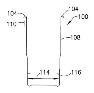
[00036] Referring to Figures 1-4, in one embodiment, a method of forming a
metal
container 100 comprises: curling outward a top edge 102 of the metal container
100 to
form a curl 104; expanding a first section 106 of the metal container 100 to
form an
expanded section 108; wherein at least part of the expanded section 108 is
below the curl
104; wherein the curling and expanding are accomplished in a single stroke of
a single die.
[00037] Figure 1 shows a cross-section of a metal container 100 before
having
undergone the step of curling outward a top edge 102 of the metal container
100 to form a
curl 104. The original diameter 114 is the diameter of the metal container 100
after it has
been formed via drawing and ironing or extrusion but before it has been
shaped, i.e. what is
commonly known in the art as a pre-form metal container. In some embodiments,
there is
no need to pre-stress the metal container 100 by narrowing or other means
before it is
expanded.
[00038] Figure 1 also shows a cross-section of a first working surface 118
of a first
expansion die 116 before contacting the metal container 100. The first working
surface 118
has a first land 124. A land is the portion of the working surface of an
expansion die having
4
CA 02858094 2014-06-03
WO 2013/096636 PCT/US2012/070979
the largest outer diameter that contacts a section of a container. It is
possible for a die to
have multiple working surfaces, each having a different land, each land having
a different
outer diameter, wherein the land having the smallest outer diameter travels
further into the
container than the land(s) having a larger outer diameter. The first expansion
die 116 of
Figure 1 is dimensioned to expand the diameter of the metal container 100 and
also to form
of curl 104 on the top edge 102 of the container 100.
[00039] Figure 2 shows the cross-section of the metal container 100 as the
top edge
102 is being curled and the first section of the metal container 100 is being
expanded to
form a first expanded section 108. The first expansion die 116 is shown at the
bottom of its
stroke inside the metal container 100.
[00040] Figure 3 shows a second expansion die 120. The second expansion
die 120
has a second working surface 122 and a second land 126.
[00041] Figure 4 shows the cross-section of the metal container 100 as a
second
section 110 (shown in Figure 2) of the metal container 100 is being expanded
to form a
second expanded section 112. The second expansion die 120 is shown at the
bottom of its
stroke inside the metal container 100. In some embodiments, the stroke of the
second
expansion die 120 extends to the bottom of the metal container 100 or
proximate to the
bottom of the metal container 100.
[00042] Referring to Figures 5-10, in another embodiment, a method of
forming a
metal container 200 comprises: curling outward a top edge 202 of the metal
container 200
to form a curl 204; expanding a first section 206 of the metal container 200
to form a first
expanded section 208 after curling the top edge 202 of the metal container
200; wherein at
least part of the first expanded section 208 is below the curl 204 and
expanding a second
section 210 of the metal container to form a second expanded section 212;
wherein at least
part of the second expanded section 212 is below the curl 204.
[00043] Figure 5 shows a cross-section of a metal container 200 before
having
undergone the step of curling outward a top edge 202 of the metal container
200 to form a
curl 204. Figure 5 also shows a cross-section of a curling die 228 before it
enters the metal
container 200. The curling die 228 is dimensioned to form the curl 204 on the
top edge 202
of the container 200 as is well-known in the art.
CA 02858094 2014-06-03
WO 2013/096636 PCT/US2012/070979
[00044] Figure 6 shows the cross-section of the metal container 200 as the
top edge
202 is being curled by the curling die 228. The curling die 228 is shown at
the bottom of its
stroke inside the metal container 200.
[00045] Figure 7 shows a first expansion die 216 before it enters the
metal container
200. The first expansion die 216 has a first working surface 218a and a first
land 224a and a
second working surface 218b and a second land 224b each dimensioned to expand
the
diameter of the metal container 200.
1000461 Figure 8 shows the cross-section of the metal container 200 as a
first section
206, shown in Figure 6, of the metal container is being expanded to form a
first expanded
section 208. The first expansion die 216 is shown at the bottom of its stroke
inside the
metal container 200.
[00047] Figure 9 shows a second expansion die 220 before it enters the
metal
container 200. The second expansion die 220 has a third working surface 222
and a third
land 226 dimensioned to expand the diameter of the metal container 200.
[00048] Figure 10 shows the cross-section of the metal container 200 as a
second
section 210, shown in Figure 9, of the metal container 200 is being expanded
to form a third
expanded section 212. The second expansion die 220 is shown at the bottom of
its stroke
inside the metal container 200.
[00049] In another embodiment of the invention, a metal container is
expanded
before a curl is formed, then expanded again after the curl has been formed.
In yet another
embodiment of the invention, a metal container is expanded after a curl has
been formed.
Then the curl is removed from the top of the container by trimming of the top
edge of the
container, The metal container may be necked after the curl is removed.
Necking can be
done by any means know in the arts such as described in US. Patent Nos.
4,512,172;
4,563,887; 4,774,839; 5,355,710 and 7,726,165. In yet a further embodiment of
the
invention, a metal container is necked before a curl is formed and expanded
after the curl
has been formed.
[00050] In all of the embodiments above, the metal comprising the metal
container
may be any metal known in the art including, but not limited to, aluminum and
steel. The
metal container may or may not have a dome in the bottom or base of the metal
container.
In some embodiments, the metal container is a one-piece metal container having
a closed
bottom. In some embodiments, the metal container is comprised of multiple
pieces of
6
CA 02858094 2014-06-03
WO 2013/096636 PCT/US2012/070979
metal seamed together. In some embodiments, a sidewall of the metal container
has a
uniform thickness from top to near the bottom of the container. In some
embodiments, a
sidewall of the metal container has a non-uniform thickness. In some
embodiments, a
sidewall of the metal container is tapered so that the thickness of the
sidewall is thinner at
the top of the container than the bottom of the container. In some
embodiments, the
thickness of a sidewall of the metal container varies along the height of the
sidewall. In
some embodiments, the sidewall is thicker at the top of the container than at
a lower
sidewall portion of the container.
[00051] Curling outward the top edge of the metal container to form a curl
may be
accomplished by any means known in the art such as die curling and rotary
curling. As
shown in Figures land 2 the step of curling outward a top edge of the metal
container may
be accomplished by inserting a curling die into the metal container at least
until the top
edge of the container curls outwardly.
[00052] In some embodiments, the presence of a curl prevents the formation
of Rider
lines during subsequent expansion steps allowing for increased expansion in a
single
expansion step without damage to the metal container. In some embodiments, the
presence of a curl also reduces axial shortening of the metal container during
expansion.
The radius of curvature of the curl and the angle of sweep of the curl affect
the degree of
expansion possible without damaging the metal container in the subsequent
expansion
step(s). In some embodiments, generally, the greater the radius of curvature
of the curl, the
greater degree of expansion possible in the subsequent expansion step without
damaging
the metal container. In some embodiments the angle of sweep of the curl is at
least 90
degrees. In some embodiments the angle of sweep of the curl is at least 180
degrees. In
some embodiments the angle of sweep of the curl is at least 270 degrees.
Increasing the
radius and/or arc length of the curl generally allows increased expansion in a
single
expansion step without damaging the metal container. In some embodiments,
curls having
an angle of sweep less than 90 degrees straighten to some extent during
subsequent
expansion, so that the angle of sweep is less after expansion. In some
embodiments, curls
having an angle of sweep greater than 180 degrees tighten during subsequent
expansion.
[00053] Expanding the metal container can be done by any means known in
the art,
including, but not limited to inserting the working surface of an expansion
die into an open
end of the metal container. Expanding using an expansion die can be performed
any way
7
CA 02858094 2014-06-03
WO 2013/096636 PCT/US2012/070979
known in the art, including as described in U.S. Patent Nos. 7,934,410 and
7,954,354, As
shown in Figures 1 and 2 a single die can be used to both curl outward the top
edge of the
container and expand a diameter of the metal container.
1000541 In some embodiments, after forming a curl, a 21 percent expansion
in
diameter of a portion of the metal container by a single land in a single
stroke of a single
expansion die is possible. In other embodiments, after forming a curl, an
expansion of
diameter of a portion of the metal container of about 5%, 10%, 15%, 20%, 25%,
30%, 35%,
40%, 45% or 50% in a single expansion step by a single land in a single stroke
of a single
expansion die is possible. Some embodiments can expand the diameter of a metal
container in one expansion step an amount that would require multiple
expansion steps in
the prior art.
[00055] In some embodiments, the land of the expansion die(s) have an
undercut
portion as shown in Figure 5 and as described in U.S. Patent Nos. 7,934,410
and 7,954,354.
In other embodiments, no undercut portion is necessary. The presence of the
undercut in
the land of the expansion die enables more aggressive expansions of the metal
container,
including the ability to take deeper/longer strokes with the expansion die.
[00056] In some embodiments, the land has a surface roughness average (Ra)
ranging
from more than or equal to 8 in to less than or equal to 32 in, so long as the
surface of the
land does not disadvantageously disrupt the aesthetic and/or functional
features of an
inside coating on the metal container in a significantly observable manner, as
described in
U.S. Patent Nos. 7,934,410 and 7,954,354.
[00057] In some embodiments, a knockout does not need to be used when
expanding
the metal container. A knockout provides a surface for releasing a metal
container from an
expansion die. In some embodiments, a pilot is used to control a top edge of a
metal
container. A pilot is a centering tool that controls movement of the top edge.
In some
embodiments, after curling the top edge of the metal container, the original
diameter of a
portion of the metal container is expanded by at least 5%, 10%, 15%, 20%, 25%,
30%, 35%,
40%, 45% or 50% by a single land in a single stroke of a single expansion die
without a
knockout and/or without first narrowing the metal container.
[00058] Embodiments of the invention are also applicable to other types and
sizes of
metal containers. For example, some embodiments may be used to form metal
beverage,
aerosol and/or food containers.
8
CA 02858094 2015-11-02
[00059] In one example, an embodiment of the invention, as described with
respect
to Figures 1-4, was used to make the metal container shown in Figure 11 using
the dies
shown in Figures 12a, 12b, 13a, 13b, 14a and 14b. The die shown In Figures 12a
and 12b
was the first die inserted into an aluminum pre-form container. As can be seen
in Figures
12a and 12b, the die has three lands. The die in Figures 12a and 12b was
inserted into the
aluminum pre-form container until the top edge of the container contacted the
shoulder
shown In Figure 12b and a curl was formed. When the die shown in Figures 12a
and 12b
was inserted into the aluminum pre-form container, the internal air pressure
of the
container was 35 psi.
[00060] Next the die shown in Figures 13a and 13b was inserted into the
expanded
and curled container. The die shown in Figures 13a and 13b also has three
lands. When the
die shown In Figures 13a and 13b was inserted into the expanded and curled
container, the
internal air pressure of the container was 35 psi.
[00061] Finally, the die shown in Figures 14a and 14b was inserted into the
curled and
expanded container, resulting in the container shown In Figure 11. The die
shown in Figures
14a and 14b only has one land. When the die shown in Figures 14a and 14b was
inserted
into the expanded and curled container, the internal air pressure of the
container was 60
psi.
[00062] Although the present invention has been described in considerable
detail
with reference to certain versions thereof, other versions are possible. The
scope of the
claims should not be limited by the preferred embodiments set forth in the
examples, but
should be given the broadest interpretation consistent with the description as
a whole.
[00063) All features disclosed in the specification, including the claims,
abstracts, and
drawings, and all the steps in any method or process disclosed, may be
combined in any
combination, except combinations where at least some of such features and/or
steps are
mutually exclusive. Each feature disclosed in the specification, Including the
claims, abstract,
and drawings, can be replaced by alternative features serving the same,
equivalent or
similar purpose, unless expressly stated otherwise. Thus, unless expressly
stated otherwise,
each feature disclosed Is one example only of a generic series of equivalent
or similar
features.
9
CA 02858094 2014-06-03
WO 2013/096636 PCT/US2012/070979
100064] Any element in a claim that does not explicitly state ''means" for
performing
a specified function or "step" for performing a specified function should not
be interpreted
as a "means or step for" clause as specified in 35 U.S.C. 112.