Note: Descriptions are shown in the official language in which they were submitted.
CA 02858114 2014-06-04
WO 2013/083673 PCT/EP2012/074596
1
MEDICAL DEVICE HAVING INTEGRATED SEQUENCE CONTROL
FIELD OF THE INVENTION
The present invention relates to fluid transfer devices, particularly to
medical mixing devices.
BACKGROUND OF THE INVENTION
Within drug delivery it may be of vital importance to maintain sterility of a
product to be ad-
ministered from its production to its administration. Many drug substances are
therefore
supplied in sealed containers having penetrable access means, such as rubber
septa, which
are adapted to be pierced by a suitable tool, e.g. a hollow needle.
For example, people with IDDM frequently attach an injection needle to their
insulin pen to
thereby penetrate a self-sealing rubber septum of an insulin containing
cartridge and estab-
lish a delivery line for subcutaneous administration. The needle and the
insulin are stored in
respective sterile environments until the point of connection.
Some pharmaceutical drugs adapted for parenteral administration are only
stable in the ad-
ministrable form a relatively short period of time. For convenience reasons,
and in order to
extend the shelf life of such a drug, it is sometimes preferred to store
individual constituents
of the drug separately and to mix them only just before a dose is needed.
Traditionally, a mixing of two substances stored in separate vials is
performed using a sy-
ringe with a needle to withdraw the substance from the one vial and inject it
into the other
vial. The syringe with the attached needle is then used to withdraw from this
vial the desired
amount of drug to be injected into the patient. This kind of manual operation
may be difficult
and may bring about some uncertainty as to the exact concentration of the
resulting drug,
because it can be difficult to completely empty a vial by such an approach.
Moreover, since
the first substance is withdrawn from one vial and transported to another vial
via a syringe
with a needle, typically including a penetration of two rubber septa in order
to establish fluid
connection to the respective vial interiors, both sterility and safety may be
compromised. To
reduce the risk of contamination of the administrable substance it is
customary to clean the
respective rubber septa with an alcohol swab before needle penetration. This,
however, is
often considered a hassle by the user, especially if she/he needs to mix the
substances and
administer the resulting drug quickly to avert a serious situation.
CA 02858114 2014-06-04
WO 2013/083673 PCT/EP2012/074596
2
US 5,466,220 (Bioject, Inc.) discloses different examples of drug vial mixing
and transfer
devices comprising one or two vials and a syringe pre-aligned and packaged in
sealed ster-
ile packages to eliminate the need for swabbing the vials before piercing and
to avoid sharp
needle exposures. While overcoming some of the drawbacks of the traditional
way of mixing
substances, the solutions comprising two vials appear bulky and operationally
cumbersome,
and the solutions including a single vial introduce a risk of carrying out the
individual opera-
tional steps in a wrong order, because the syringe plunger is operable before
connection of
the vial and the syringe, thereby enabling a delivery of some of the syringe
contents to the
exterior of the vial.
WO 97/46203 (Applied Research Systems ARS Holding N.V.) discloses a pre-
assembled
pack for a drug reconstituting device, which pack comprises a vial co-axially
aligned with a
cartridge and separated therefrom by a double-ended needle element. In the pre-
use state
of the device the needle element is shielded at each end by a slidable bung,
providing for
closed, sterile needle chambers. Like the above mentioned prior art solutions
including a
single vial, this pack also lacks a mechanism which prevents it from being
manipulated erro-
neously to e.g. expel the contents of the cartridge before fluid connection to
the vial has
been established.
SUMMARY OF THE INVENTION
It is an object of the invention to provide a solution which eliminates, or at
least reduces,
drawbacks of the prior art.
In particular, it is an object of the invention to provide a medical device
which is simple to
operate and which offers an automatic sequence control guaranteeing a correct
sequence of
at least some key operations of the device.
It is a further object of the invention to provide a fluid transfer device
offering safe and sterile
establishment of fluid connection to a substance container.
It is an even further object of the invention to provide a medical mixing
device comprising a
user operable actuation mechanism which cannot be operated until fluid
communication is
properly established between respective substance containing reservoirs.
CA 02858114 2014-06-04
WO 2013/083673 PCT/EP2012/074596
3
In the disclosure of the present invention, aspects and embodiments will be
described which
will address one or more of the above objects and/or which will address
objects apparent
from the below disclosure as well as from the description of exemplary
embodiments.
In a first aspect of the invention a medical device is provided comprising a
base member, a
first container comprising a first container interior adapted to accommodate a
first substance,
and a first container closure for fluidly sealing the first container
interior, and a second con-
tainer comprising a second container interior adapted to accommodate a second
substance,
and a second container closure for fluidly sealing the second container
interior. The medical
device further comprises fluid connection means for establishing fluid
communication be-
tween the first container interior and the second container interior, and
fluid transfer means
for causing transfer of the first substance to the second container interior.
A cover is remov-
ably mounted on a cover receiving portion to shield at least a portion of the
fluid transfer
means and is operatively coupled with the fluid connection means to cause a
relative motion
between the fluid connection means and at least one of the first container
closure and the
second container closure in response to a relative motion between the cover
and the base
member. An incorporated cover engagement mechanism is configured to prevent
movement
of the cover in a dismounting direction relative to the cover receiving
portion when the cover
and the base member are in a first relative position, in which the first
container interior and
the second container interior are fluidly unconnected, and to allow movement
of the cover in
a dismounting direction relative to the cover receiving portion when the cover
and the base
member are in a second relative position in which fluid communication is
established be-
tween the first container interior and the second container interior.
Such a construction enables the provision of a medical device capable of
transferring a sub-
stance from one container to another, which device may be operated by a user
to execute
the transfer only after removal of a protective cover and proper establishment
of fluid com-
munication between the respective container interiors. Thereby, it is ensured
that a prema-
ture fluid transfer cannot take place and, consequently, that no substance
wastage can oc-
cur. This is particularly relevant when a specific volumetric ratio of the
first substance and
the second substance is needed to produce a predictable medical treatment
outcome. It is
further relevant in order to avoid leakage within the device potentially
causing damage to the
internal components as well as giving rise to a perception of the product
being unreliable.
The construction further provides a medical mixing device which offers
separate storage of
the individual substances to be mixed and simple, easy and safe establishment
of a fluid
pathway between the substances, requiring a minimum number of manual
operational steps.
CA 02858114 2014-06-04
WO 2013/083673 PCT/EP2012/074596
4
In the present context, "movement of the cover in a dismounting direction
relative to the
cover receiving portion" means a movement of the cover in a direction that
will eventually
lead to a dismounting from the cover receiving portion. Such movement may
include a trans-
lation, e.g. along an axis defined by the cover receiving portion, a rotation,
e.g. about an axis
defined by the cover receiving portion, or a spiralling movement of the cover
relative to the
cover receiving portion.
The first container may be a fixed volume reservoir or a variable volume
reservoir capable of
selective decrease and/or increase of an internal volume. A suitable variable
volume reser-
voir may e.g. comprise a user operable actuator operatively coupled with a
movable wall,
one example of such a reservoir being a syringe which comprises a movable
piston adapted
for actuation by a user operable piston rod. In that case the cover may be
adapted to shield
the actuator when mounted on the cover receiving portion. Similarly, the
second container
may have a fixed or variable internal volume.
In particular embodiments the first container and the second container are co-
axially ar-
ranged along a general axis, and the fluid connection means is arranged at
least partially
between the first container and the second container. Thereby, an attractive
slender configu-
ration of the medical device may be provided which makes it suitable for being
carried about
in e.g. a pocket or a handbag.
The fluid connection means may comprise a central portion carrying one or more
pointed
hollow shaft members, such as one or more needles or spikes. In particular,
the central por-
tion may carry either a single needle/spike or two oppositely pointing,
fluidly connected,
needles/spikes. The central portion may be encircled by a cylindrical sleeve
extending sub-
stantially parallel to the one or more hollow shaft members.
The fluid transfer means may comprise an initial pressure difference between
the first con-
tamer interior and the second container interior or, alternatively, an
actuation mechanism for
selectively establishing a pressure difference between the two container
interiors. The actua-
tion mechanism may e.g. be adapted to selectively create an excess pressure in
the first
container or a negative pressure in the second container for transferring the
first substance
from the first container to the second container. The actuation mechanism may
further be
adapted to selectively create an excess pressure in the second container or a
negative
pressure in the first container for transferring a mixture of the first
substance and the second
substance from the second container to the first container.
CA 02858114 2014-06-04
WO 2013/083673 PCT/EP2012/074596
The actuation mechanism may be arranged in connection with either the first
container or
the second container, such as e.g. in the form of a piston rod in a syringe,
or it may be ar-
ranged separately from the two containers.
The base member may e.g. comprise a holder, protector and/or a support for one
of the con-
5 tainers. For example, in case the container is of the fixed volume
reservoir type, such as e.g.
a vial, the base member may be a protective cover for the reservoir. In case
the container is
of the variable volume reservoir type, such as e.g. a cartridge, the base
member may be a
reservoir holder. Alternatively, or additionally, the base member may be a
housing or a part
of a housing for internal components of the medical device, or it may simply
be a component
with respect to which the container is translationally or rotationally fixed.
The operative coupling between the cover and the fluid connection means may
comprise a
mechanical coupling between the cover and one of the first container and the
second con-
tainer and a mechanical coupling between the container in question and the
fluid connection
means. Specifically, the cover may mechanically interface, e.g. by engagement
or abutment,
a portion of the first container which is immovable relative to a first
container outlet. Thereby,
it is ensured that the pressure in the first container interior remains fixed
when the first con-
tainer is moved, regardless of which type of container is employed.
The mechanical interaction between the cover and the first container may be
realised via
coupling means, such as protrusions, on the inner surface of the cover
structured to inter-
face with a radially outwardly extending flange portion on or associated with
the first con-
tainer to enable joint motion of the cover and the first container in a first
direction.
In some embodiments, the cover and the first container are coupled to enable
joint transla-
tional motion of the two in a first direction along the general axis.
The relative motion between the cover and the base member that induces a
relative motion
between the fluid connection means and at least one of the first container
closure and the
second container closure may be purely translational, purely rotational or
helical. In some
embodiments the relative motion between the cover and the base member
comprises a con-
verging translational relative motion.
The cover engagement mechanism may comprise a releasable interlocking of the
cover and
the cover receiving portion, e.g. realised via a position dependable
interaction between re-
CA 02858114 2014-06-04
WO 2013/083673 PCT/EP2012/074596
6
spective portions of the cover, the cover receiving portion, and a wall
extending along the
general axis.
The cover receiving portion may form part of a first container support member,
e.g. a first
container holder, and the wall may form part of a second container support
member, e.g. a
The cover engagement mechanism may specifically comprise a radially
deflectable portion
of the cover receiving portion arranged in releasable engagement with the
cover. This ra-
dially deflectable portion of the cover receiving portion may be biased
radially outwardly rela-
tive to the general axis but configured to deflect inwardly when subjected to
a radially in-
The cover engagement mechanism may be structured such that radial inwards
deflection of
To establish proper fluid communication between the first container interior
and the second
CA 02858114 2014-06-04
WO 2013/083673 PCT/EP2012/074596
7
cover engagement mechanism is designed to enable a release of the cover only
when the
cover and the base member have undergone relative motion to effectively cause
a relative
translational motion of magnitude x1 between the first container closure and
the fluid connec-
tion means and a relative translational motion of magnitude x2 between the
second container
closure and the fluid connection. Thereby, it is ensured that the cover cannot
be dismounted
from the cover receiving portion when e.g. fluid connection has been
established to only one
of the containers. In particular embodiments, the cover engagement mechanism
is designed
to enable a release of the cover only when the cover and the base member have
undergone
a relative converging translational motion of at least a magnitude xr = x1 +
x2.
A portion, e.g. a tip portion, of the radially deflectable portion may be
adapted for sliding
abutment with the wall during movement of the cover and the base member from
the first
relative position to the second relative position.
In some embodiments the first container is a variable volume reservoir, e.g. a
syringe, re-
leasably fixed to a reservoir holder such that upon transfer of the first
substance from the
first container to the second container and subsequent transfer of a mixture
of the first sub-
stance and the second substance from the second container to the first
container, the first
container may be removed from the reservoir holder and used with suitable
delivery means,
such as a cannula or an infusion set, for application of the mixed product to
a desired site of
administration.
The medical device may further comprise a blocking element movable with
respect to the
base member from a first position in which relative motion between the cover
and the base
member from the first relative position to the second relative position is
prevented to a sec-
ond position in which relative motion between the cover and the base member
from the first
relative position to the second relative position is allowed. The first
position may be a first
translational or rotational position of the blocking element relative to the
base member and
the second position may be a second translational or rotational position of
the blocking ele-
ment relative to the base member. For example, in the second position the
blocking element
may be completely removed from the medical device.
The blocking element may, when positioned in the first position, prevent
axially converging
relative motion between the cover and the base member, in which case the
blocking element
may act as a spacer element separating the cover from the base member.
CA 02858114 2014-06-04
WO 2013/083673 PCT/EP2012/074596
8
The blocking element may comprise a radially inwardly extending flange for
supporting the
fluid connection means in a pre-use state of the medical device. This will
assist in defining
and maintaining a correct pre-use positioning of the fluid connection means
relative to the
respective container closures, thereby ensuring that none of the container
closures are pre-
maturely penetrated. The blocking element may further comprise a dedicated
interface for
user operation to enable an easy switch from the first position to the second
position. The
dedicated interface may e.g. comprise a pull ring for tearing away the
blocking element.
In a second aspect of the invention a medical device is provided comprising a
base member,
a container comprising a container interior adapted to accommodate a
substance, and a
container closure for fluidly sealing the container interior, and fluid
connection means for
establishing fluid connection to the container interior. A cover removably
mountable on a
cover receiving portion is operatively coupled with the fluid connection means
to cause a
relative motion between the fluid connection means and the container closure
in response to
a relative motion between the cover and the base member. The medical device
further com-
prises a cover engagement mechanism configured to prevent movement of the
cover in a
dismounting direction relative to the cover receiving portion when the cover
and the base
member are in a first relative position in which the fluid connection means
and the container
interior are fluidly separated and to allow movement of the cover in a
dismounting direction
relative to the cover receiving portion when the cover and the base member are
in a second
relative position in which the fluid connection means and the container
interior are fluidly
connected.
The fluid connection means may e.g. comprise a hollow needle or spike element
having ei-
ther one or two pointed end portions.
In some embodiments, the medical device is a fluid transfer device comprising
a) a vial
comprising a substance in a vial interior and a fluid tight vial seal, b) a
vial holder to which
the vial is firmly attached, c) fluid connection means capable of undergoing
relative motion
with respect to the vial seal from a first position in which the fluid
connection means and the
vial interior are fluidly unconnected to a second position in which the fluid
connection means
and the vial interior are fluidly connected, d) a cover for shielding at least
a portion of the
fluid connection means, the cover being operatively coupled with the fluid
connection means
to cause a relative motion between the fluid connection means and the vial
seal in response
to a relative motion between the cover and the vial holder, e) a cover
receiving portion struc-
tured for engagement or abutment with the cover when the cover is mounted to
shield the at
CA 02858114 2014-06-04
WO 2013/083673 PCT/EP2012/074596
9
least a portion of the fluid connection means, and f) a cover engagement
mechanism struc-
tured to prevent movement of the cover in a dismounting direction relative to
the cover re-
ceiving portion when the cover and the vial holder are in a first relative
position and to allow
movement of the cover in a dismounting direction relative to the cover
receiving portion
when the cover and the vial holder are in a second relative position. The
fluid connection
means comprises a hollow shaft capable of entering the vial interior and
attachment means
fluidly connected to the hollow shaft, the attachment means being structured
to receive an
outlet portion of a variable volume reservoir.
In a third aspect of the invention a drug delivery device is provided
comprising a) a variable
volume drug reservoir, e.g. a cartridge, capable of holding a drug substance
in a reservoir
interior sealed by a penetrable septum, b) a support member configured to
encircle at least a
portion of the reservoir, c) an actuator mechanism for altering the volume of
the reservoir
interior, the actuator mechanism being arranged at least partially in a
housing, d) a needle
assembly comprising a needle hub carrying a double-pointed needle cannula and
attach-
ment means for attaching the needle hub to the reservoir or the support
member, e) a re-
movable cap adapted to cover at least a portion of the reservoir, the cap
being operatively
coupled with the needle assembly to cause a relative motion between the needle
assembly
and the penetrable septum in response to a relative motion between the cap and
the reser-
voir, f) a cap receiving portion structured for engagement or abutment with
the cap when the
cap is mounted to cover the at least a portion of the reservoir, and g) a cap
engagement
mechanism configured to prevent movement of the cap in a dismounting direction
relative to
the cover receiving portion when the cap and the reservoir are in a first
relative position, in
which the needle cannula and the reservoir interior are fluidly separated, and
to allow
movement of the cap in a dismounting direction relative to the cap receiving
portion when
the cap and the reservoir are in a second relative position in which the
needle cannula and
the reservoir interior are fluidly connected.
The drug delivery device may further comprise a blocking element, or spacer
element, which
must be removed to allow relative converging motion of the cover and the
housing. The
blocking element may thus serve both as a safety against unintended
penetration of the res-
ervoir septum by the needle cannula and as a tamper indicator.
In the present specification, reference to a certain aspect or a certain
embodiment (e.g. "an
aspect", "a first aspect", "one embodiment", "an exemplary embodiment", or the
like) signi-
fies that a particular feature, structure, or characteristic described in
connection with the re-
CA 02858114 2014-06-04
WO 2013/083673 PCT/EP2012/074596
spective aspect or embodiment is included in, or inherent of, at least that
one aspect or em-
bodiment of the invention, but not necessarily in/of all aspects or
embodiments of the inven-
tion. It is emphasized, however, that any combination of features, structures
and/or charac-
teristics described in relation to the invention is encompassed by the
invention unless ex-
5 pressly stated herein or clearly contradicted by context.
The use of any and all examples, or exemplary language (e.g., such as, etc.),
in the text is
intended to merely illuminate the invention and does not pose a limitation on
the scope of
the same, unless otherwise claimed. Further, no language or wording in the
specification
should be construed as indicating any non-claimed element as essential to the
practice of
10 the invention.
BRIEF DESCRIPTION OF THE DRAWINGS
In the following the invention will be further described with references to
the drawings,
wherein
Fig. 1 shows an exploded view of a medical device according to an embodiment
of the in-
vention,
Fig. 2 shows a longitudinal section view of the device of Fig. 1, in a pre-use
state,
Fig. 3 shows a close-up longitudinal section view of the device, in an initial
use state, detail-
ing the cover engagement mechanism and the fluid connection means,
Fig. 4a and 4b show close-up longitudinal section views of the device in
different use states,
Fig. 5 shows a close-up longitudinal section view of the device after fluid
communication has
been established between the container interiors, and
Fig. 6 shows a close-up longitudinal section view of the device after removal
of the outer
cover.
In the figures like structures are mainly identified by like reference
numerals.
CA 02858114 2014-06-04
WO 2013/083673 PCT/EP2012/074596
11
DESCRIPTION OF EXEMPLARY EMBODIMENTS
When in the following relative expressions, such as "upwards" and "downwards",
are used,
these refer to the appended figures and not necessarily to an actual situation
of use. The
shown figures are schematic representations for which reason the configuration
of the differ-
ent structures as well as their relative dimensions are intended to serve
illustrative purposes
only.
Fig. 1 is an exploded perspective view of a mixing device 1 for reconstitution
of a powdered
drug in a vial 20 using a solvent from a syringe 10. The vial 20 comprises a
wall 21 having
an opening which is sealed by a vial stopper 23 (see Fig. 2) and a seal cap
22. A tower 25
protrudes axially from the seal cap 22 in the direction away from the vial 20.
The tower 25
has an inner circumferential sealing rim 26 at its end portion, the purpose of
which is ex-
plained below.
The vial 20 is arranged in a vial protector 2 which serves to protect the vial
20. In the dis-
closed embodiment the wall 21 is made of glass and the vial protector 2 is
made of plastic.
Other suitable materials may, however, be chosen, depending on the specific
application of
the mixing arrangement 1.
The proximal portion of the vial protector 2 has an enlarged diameter to
accommodate a
distal portion of a sleeve member 40. The sleeve member 40 comprises an
axially extending
wall 46 and an opening 49 in the wall 46, the opening 49 being arranged to
allow release of
a cap 4 from the mixing device 1 in a manner which is described in detail
below. In this par-
ticular embodiment the sleeve member 40 is arranged non-translationally
relative to the vial
protector 2.
The sleeve member 40 is designed to accommodate a connector piece 50 and to
interact
with a distal portion of a syringe holder 30. The syringe holder 30 comprises
a proximal sup-
porting frame 35 adapted to receive and hold a portion of the syringe 10 and a
distal cap
receiving portion 36 in the form of a tubular segment provided with a number
of circumferen-
tially spaced apart flexible arms 37 as well as a number of openings 39. In
the transition be-
tween the supporting frame 35 and the cap receiving portion 36 a number of
lock snaps 38
are circumferentially distributed. The lock snaps 38 are adapted to fix a
stopper fastener 70
to the syringe holder 30 by interaction with a pair of protrusions 72. The
stopper fastener 70
holds a syringe stopper 60 in place so as to sealingly close an outlet of the
syringe 10. The
syringe 10 is of the Luer-Lok type having a threaded Luer collar 13 at the
distal end of a bar-
CA 02858114 2014-06-04
WO 2013/083673 PCT/EP2012/074596
12
rel 11. A filter 69 is optionally arranged in the syringe stopper 60 to filter
out any impurities of
a passing liquid. The proximal end portion of the barrel 11 is shaped to
provide a circumfer-
ential collar 17 having a slightly greater outer diameter than the barrel 11
itself. A piston rod
14 extends from the interior of the barrel 11 and has a proximal push face 15
for operation
by a user. The cap 4, which is non-deformable in ordinary use conditions and
which is
adapted to fit over the syringe 10 and be received by the cap receiving
portion 36, is pro-
vided with a number of circumferentially spaced apart openings 9 at its distal
end portion.
Fig. 1 also shows a spacer element 90 adapted for initial pre-use arrangement
between the
cap 4 and the vial protector 2 to ensure that an axial spacing between the two
is maintained.
The spacer element 90 is a bendable, or segmented, band which can be removed
by per-
forming a peeling action.
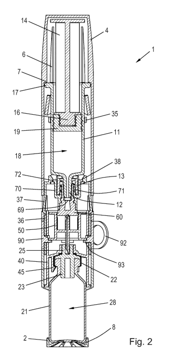
Fig. 2 is a longitudinal section view of the mixing device 1 in the assembled
state, prior to a
first use thereof, showing further details of the arrangement. This state
corresponds to the
one in which the mixing device 1 is intended to be delivered by the
manufacturer. The piston
rod 14 is in a retracted position in the barrel 11, thereby defining a syringe
interior 18 capa-
ble of holding a certain volume of a solvent (not shown). The piston rod 14 is
coupled firmly
to a piston 19 via a jagged coupling head 16. The cap 4 is fitted snugly
around the collar 17,
providing a user friendly slender configuration of the mixing device 1.
A Luer 12, defining the outlet of the syringe 10, protrudes into the hollow
interior of the cap
receiving portion 36 and is retained therein via a screw thread connection
between the Luer
collar 13 and a threaded inner portion 71 of the stopper fastener 70. A
portion of the syringe
stopper 60 is wedged between the Luer 12 and the threaded inner portion 71 and
thereby
provides a fluid tight engagement with the exterior surface of the Luer 12.
The syringe stop-
per 60 has a penetrable section 61 (see Fig. 3) allowing for easy rupturing of
the syringe
sealing by a suitable tool.
The connector piece 50 is slidably received in the hollow interior of the
sleeve member 40
and is axially supported by an interior flange 93 on the spacer element 90,
the flange 93
defining an exact initial position of the connector piece 50 relative to the
penetrable section
61 and a penetrable section 24 (see Fig. 3) of the vial stopper 23. The sleeve
member 40
has a number of circumferentially spaced apart catch arms 45 extending
downwards from a
transversal interior portion for securing firm attachment of the vial 20. The
wall 21 defines a
vial interior 28 capable of holding an amount of powdered drug (not shown) to
be reconsti-
CA 02858114 2014-06-04
WO 2013/083673 PCT/EP2012/074596
13
tuted by the solvent from the syringe 10. The wall 21 is flexibly supported by
leaf springs 8 in
the bottom of the vial protector 2 to account for manufacturing tolerances.
In Fig. 2 the cap 4 is mounted on the cap receiving portion 36 whereby the
entire syringe 10
is shielded from the surroundings. A number of ribs 6 extend axially along an
inner portion of
the cap 4, each of the ribs 6 having a distally oriented contact face 7
adapted for interaction
with the collar 17. The respective flexible arms 37 are biased such that they
flex into the re-
spective openings 9 in the cap 4. Each flexible arm 37 is provided with an
inclined surface
which interacts with an inclined surface of the corresponding opening 9 such
that an axial
proximally directed force applied to the cap 4 will result in a radially
inwards directed force
on the flexible arms 37. In this pre-use state of the mixing device 1 the
flexible arms 37 abut
the sleeve member 40 and are prevented from inwards deflection by the wall 46.
Thereby,
the cap 4 is prevented from being dismounted from the cap receiving portion
36. It is noted
that in the shown embodiment the openings 9 are cut-outs in the cap 4. This,
however, need
not be the case, as the cap 4 could alternatively be provided with e.g.
grooves in inner wall
portions. To start using the mixing device 1 the user must first remove the
spacer element
90 by pulling a pull ring 92 tangentially.
Fig. 3 is a close-up longitudinal section view of a central portion of the
mixing device 1 in a
pre-connection state where the spacer element 90 has just been removed. In
this state the
distal end face of the cap 4 and the proximal end face of the vial protector 2
are axially
spaced apart a distance, L1. The figure details the connector piece 50 and its
initial ar-
rangement with respect to the syringe 10 and the vial 20. The connector piece
50 comprises
a cylindrical sleeve body 51 with radially outwardly projecting flanges 58 at
each end, serv-
ing to stabilise the connector piece 50 in the interior of the sleeve member
40. The sleeve
body 51 supports a transverse spike base 54 which carries a distally pointing
hollow spike
member 52 as well as a proximally pointing hollow spike member 53. In the
depicted state of
the mixing device 1 the hollow spike member 53 is arranged just distally of
the penetrable
section 61 of the syringe stopper 60 and the hollow spike member 52 is
arranged just proxi-
mally of the penetrable section 24 of the vial stopper 23. The syringe 10 and
the vial 20 are
therefore fluidly unconnected at this point. The syringe stopper 60 has at its
distal end por-
tion a circumferential sealing lip 62 which is adapted to sealingly engage
with an interior por-
tion of the sleeve body 51 to provide a fluid tight compartment 56 for the
hollow spike mem-
ber 53. Similarly, the tower 25 with the sealing rim 26 provides a fluid tight
compartment 57
for the hollow spike member 52. This particular construction thus enables the
incorporation
of a sterilised sub-assembly comprising the syringe stopper 60, the connector
piece 50 and
CA 02858114 2014-06-04
WO 2013/083673 PCT/EP2012/074596
14
the vial stopper 23 during assembly of the mixing device 1, and further
ensures that sterility
of the respective hollow spike members 52, 53 is maintained throughout
storage, transporta-
tion and use of the mixing device 1 with no need for additional sterile
barriers.
In order to enable removal of the cap 4 from the cap receiving portion 36 the
cap 4 initially
needs to be pressed towards the vial protector 2. The needed relative
converging motion of
the cap 4 and the vial protector 2 will cause relative converging motion
between the syringe
stopper 60 and the connector piece 50 as well as between the connector piece
50 and the
vial stopper 23, as will be clear from the below. The exact sequence of motion
of the syringe
stopper 60 relative to the connector piece 50 and of the connector piece 50
relative to the
vial stopper 23 depends on the frictional characteristics of the internal
components of the
mixing device 1 and the specific arrangement of these components. The sequence
may be
known, as dimensioned by the manufacturer, or arbitrary. Figs. 4a and 4b
illustrate the two
extremes where complete converging relative motion between the syringe stopper
60 and
the connector piece 50 takes place before any relative motion is induced
between the con-
nector piece 50 and the vial stopper 23 (Fig. 4a) and where complete
converging relative
motion between the connector piece 50 and the vial stopper 23 takes place
before any rela-
tive motion is induced between the syringe stopper 60 and the connector piece
50 (Fig. 4b).
Fig. 4a is a close-up longitudinal section view of the same portion of the
mixing device 1 as
was depicted in Fig. 3. However, in Fig. 4a the cap 4 has been pressed
downwards towards
the vial protector 2, slaving the syringe 10 via the interaction between the
contact faces 7
and the collar 17. The syringe 10 has been accompanied by the syringe holder
30 due to the
above described fixed relationship between the Luer collar 13, the stopper
fastener 70 and
the syringe holder 30. Since the sleeve member 40 is unable to move axially
with respect to
the vial protector 2 the downward movement of the syringe holder 30 has caused
the flexible
arms 37 to slide axially along the wall 46. The axial distance between the
distal end face of
the cap 4 and the proximal end face of the vial protector 2 is now L2, i.e.
the cap 4, and
thereby the flexible arms 37, has travelled the distance x1 = L1 ¨ L2 towards
the vial protector
2.
In the illustrated situation the converging relative motion between the cap 4
and the vial pro-
tector 2 has caused the syringe stopper 60 to travel the same axial distance
towards the
spike base 54, whereby the spike member 53 has penetrated the penetrable
section 61 and
entered an interior space 68 between the penetrable section 61 and the Luer
12. During the
travel of the syringe stopper 60 the circumferential sealing lip 62 has slid
along the inner wall
CA 02858114 2014-06-04
WO 2013/083673 PCT/EP2012/074596
of the sleeve body 51. To avoid a resulting pressure build up in the
compartment 56 one or
more vents 59 are provided in the sleeve body 51, allowing gas, e.g. air,
entrapped there-
within to escape. As can be seen no fluid communication between the syringe
interior 18
and the vial interior 28 has yet been established and the flexible arms 37
still abut the sleeve
5 member 40, which means that the cap 4 is still retained on the cap
receiving portion 36.
Further movement of the cap 4 and the syringe 30 towards the vial protector 2
will cause
relative motion between the connector piece 50 and the vial stopper 23,
whereby the pene-
trable section 24 will be penetrated by the spike member 52.
Fig. 4b is a close-up longitudinal section view of the same portion of the
mixing device 1 as
10 was depicted in Fig. 3. However, just as in Fig. 4a, the cap 4 has been
pressed downwards
towards the vial protector 2, slaving the syringe 10 via the interaction
between the contact
faces 7 and the collar 17. The syringe 10 has been accompanied by the syringe
holder 30
due to the fixed relationship between the Luer collar 13, the stopper fastener
70 and the sy-
ringe holder 30. Again, since the sleeve member 40 is unable to move axially
with respect to
15 the vial protector 2 the downward movement of the syringe holder 30 has
caused the flexible
arms 37 to slide axially along the wall 46. The axial distance between the
distal end face of
the cap 4 and the proximal end face of the vial protector 2 is in this
situation L3, i.e. the cap
4, and thereby the flexible arms 37, has travelled the distance x2 = L1 ¨ L3
towards the vial
protector 2.
In the illustrated situation the converging relative motion between the cap 4
and the vial pro-
tector 2 has caused the connector piece 50 to travel the same axial distance
towards the vial
stopper 23, whereby the spike member 52 has penetrated the penetrable section
24 and
entered the vial 20. As can be seen no fluid communication between the syringe
interior 18
and the vial interior 28 has yet been established and the flexible arms 37
still abut the sleeve
member 40, which means that the cap 4 is still retained on the cap receiving
portion 36.
Further movement of the cap 4 and the syringe 30 towards the vial protector 2
will cause
relative motion between the syringe stopper 60 and the connector piece 50,
whereby the
penetrable section 61 will be penetrated by the spike member 53.
Fig. 5 is a close-up longitudinal section view of the same portion of the
mixing device 1 as
was depicted in Fig. 3. In Fig. 5 the cap 4 has been pressed towards the vial
protector 2 a
distance corresponding to complete converging motion between the syringe
stopper 60 and
the connector piece 50 and between the connector piece 50 and the vial stopper
23. There-
CA 02858114 2014-06-04
WO 2013/083673 PCT/EP2012/074596
16
by, the spike member 52 has properly penetrated the penetrable section 24 of
the vial stop-
per 23 and the spike member 53 has properly penetrated the penetrable section
61 of the
syringe stopper 60, establishing fluid communication between the syringe
interior 18 and the
vial interior 28 via a lumen 55 extending through the spike members 52, 53 and
the spike
base 54.
In this state of the mixing device 1 the tips of the flexible arms 37 are
aligned with the re-
spective openings 49 in the sleeve member 40. A subsequent upwards directed
force ap-
plied to the cap 4 will therefore cause the flexible arms 37 to deflect out of
engagement with
the inclined surfaces of the openings 9 and into the openings 49, allowing the
cap 4 to be
pulled off. Hence, a design is provided which ensures that the cap 4 is only
dismountable
from the cap receiving portion 36 once a proper fluid connection is
established between the
syringe 10 and the vial 20.
Fig. 6 shows the mixing device 1 after removal of the cap 4. In this state of
the mixing device
1 the piston rod 14 is exposed and is now operable by the user, e.g. via the
push face 15.
Operation of the mixing device
In the following a situation of use of the mixing device 1 will be described.
To enable recon-
stitution of the powdered drug the user grips the mixing device 1 and peels
off the spacer
element 90 by pulling the pull ring 92. This removes the axial support for the
connector piece
50 as well as the barrier for axial movement of the cap 4. After having
removed the spacer
element 90 the user holds the vial protector 2 in one hand and the cap 4 in
the other and
then moves the two hands towards each other to bring together the distal end
face of the
cap 4 and the proximal end face of the vial protector 2. Alternatively, the
user places the vial
protector 2 on an even surface, such as e.g. a table, and, using only one
hand, presses the
cap 4 towards the vial protector 2.
As the cap 4 moves towards the vial protector 2 the respective contact faces 7
exert a driv-
ing force on the collar 17, thereby causing the syringe 10 to move towards the
vial 20. The
syringe 10 pushes the stopper fastener 70 in the same direction and the
stopper fastener 70
slaves the syringe holder 30 which causes the flexible arms 37 to slide along
the wall 46,
while the syringe stopper 60 and the vial stopper 23 converge. The initial
position of the sy-
ringe holder 30 relative to the sleeve member 40 as well as the axial
placement of the open-
ings 49 in the wall 46 are such that when the current clearance, Lc, between
the distal end
face of the cap 4 and the proximal end face of the vial protector 2 satisfies
Lc = L1 ¨ (x1 + x2)
CA 02858114 2014-06-04
WO 2013/083673 PCT/EP2012/074596
17
the tips of the flexible arms 37 are aligned with the openings 49. At this
relative position of
the syringe holder 30 and the sleeve member 40 the cap 4 is dismountable from
the cap
receiving portion 36 because an axial retraction of the cap 4 from the vial
protector 2 will
cause the inclined surfaces of the openings 9 to force the flexible arms 37
radially inwards
into the openings 49.
Also, at this relative position of the syringe holder 30 and the sleeve member
40 the spike
members 52, 53 have properly penetrated the respective penetrable sections 24,
61 to es-
tablish fluid communication between the syringe interior 18 and the vial
interior 28.
The cap 4 is now pulled away from the vial protector 2, whereby the piston rod
14 becomes
Once the mixed product is fully contained within the syringe 10, the syringe
10 is removed