Note: Descriptions are shown in the official language in which they were submitted.
CA 02858124 2014-06-03
WO 2013/096011
PCT/US2012/068968
SORTER SLAT ATTACHMENT
BACKGROUND OF THE INVENTION
The present invention is directed to a positive displacement shoe and slat
sorter
and in particular to a technique for easily removing and attaching slats to
wheel
assemblies.
Positive displacement sorters include a large number of generally parallel
slats
and wheel assemblies connected to opposite ends of the slats to hold the slats
together
in a web and to allow the web to travel under a motive force. The wheel
assemblies
may include covers, known as cap angles, in order to allow articles to be
diverted off of
the sorter without contacting the wheel assemblies. Some installations also
include
guards to restrict articles from falling off of the sorter in the case of a
jamb condition.
The presence of cap angles, guards, and the like, make it cumbersome to remove
a slat, such as to replace a pusher shoe, access the interior of the sorter,
or the like.
Therefore, proposals have been made to provide a slat-mounting arrangement
that
allows removal and reattachment of the slats with respect to the wheel
assemblies
without the need to remove the cap angle and/or the guards.
SUMMARY OF THE INVENTION
The present invention provides an attachment technique for removeably
attaching slats of a shoe and slat sorter to wheel assemblies in a manner that
is both easy
to operate and is robust in construction.
A positive displacement sorter, according to an aspect of the invention,
includes
a plurality of parallel laterally extending slats and a pair of wheel
assemblies, each
interconnecting common end portions of the slats thereby defining an endless
web that
travels in a longitudinal direction. An upper surface of the web defines an
article-
conveying surface. A plurality of pusher shoes travel along the slats in order
to laterally
displace articles on the conveying surface. A plurality of attachment
mechanisms are
provided. Each attaches an end portion of one of the slats to one of the wheel
assemblies. Each of the attachment mechanisms includes a shoulder and a collar
and at
least one locking member. The collar engages the shoulder thereby providing
retention
of the slat to the wheel assembly. The locking member provides retention of
the collar
on the shoulder. The locking member includes a generally horizontally moveable
-1-
CA 02858124 2014-06-03
WO 2013/096011
PCT/US2012/068968
elongated member engaging an opening. The elongated member is on either the
slat or
the wheel assembly with the opening on the other of said slat or the wheel
assembly.
The shoulder may be on the slat or wheel assembly and the collar on the other
of
the slat or wheel assembly. The shoulder may be on the wheel assembly and the
collar
is on the slat, with the generally horizontally moveable elongated member
being on the
slat and the opening on the wheel assembly.
Each of the wheel assemblies may include a generally vertical plate at each of
the slats, wherein the openings and shoulder are at the generally vertical
plate. The
generally vertical plate may have a set of through-holes mounting the
shoulder, with the
through-holes being symmetrical with the locking openings. In this manner, a
common
configuration of the vertical plate may be used in both of the wheel
assemblies.
The shoulder may include at least two spaced apart horizontally extending
studs
with at least two of the sockets engaging the studs. Each of the studs may
include an
enlarged head in order to laterally retain one of the sockets on that stud.
The studs may
be circular in cross section and the sockets may be semi-circular recesses.
The generally horizontally moveable elongated member may be a pin that is
generally laterally moveable to engage the opening. A biasing mechanism may be
provided to bias the pin into engagement with the opening. A retention
fastener may be
provided that passes through an opening in a neck of a cylinder and engages
the pin to
retain the pin in the cylinder against the bias of the biasing mechanism.
A pin retraction tool may be provided that is adapted to retract the pin from
the
opening to allow the associated slat to be connected to or disconnected from
the wheel
assembly. The locking member may be a plurality of spaced apart pins and
biasing
mechanisms and the pin retraction tool may have arms positioned to engage the
plurality of pins to generally concurrently retract the pins from the
openings. The pin
retraction tool may be adapted to engage an end portion of each pin at the
wheel
assembly. The pin retraction tool may be adapted to engage the generally
vertical plate
in the wheel assembly to retract said pins from the openings. A tapered
portion may be
provided at each of the arms.
A method of removeably attaching a slat to a positive displacement sorter,
according to an aspect of the invention, includes having attachment mechanisms
-2-
CA 02858124 2014-06-03
WO 2013/096011
PCT/US2012/068968
connecting slats to chain assemblies. Each attachment mechanism includes a
shoulder
and a collar and at least one locking member. The collar engages the shoulder
thereby
providing retention of the slat to one of said wheel assemblies. The locking
member
provides retention of the collar on the shoulder. The locking member includes
a
generally horizontally moveable elongated member and an opening. The method
further includes horizontally retracting the elongated member from the opening
and
separating said collar from the shoulder to remove the slat.
A pin retraction tool may be used to retract the pin from the opening to allow
the
associated slat to be connected to or disconnected from the wheel assembly.
The
locking member may include a plurality of spaced apart pins and biasing
mechanisms
and the pin retraction tool having arms positioned to engage the pins and
generally
concurrently retracting the pins from the openings. The pin retraction tool
may pivot
against one of the wheel assemblies to retract the pins from the openings. An
end
portion of each said pin may be engaged at the wheel assembly with the pin
retraction
tool. The pin retraction tool may pivot about a generally vertical plate of
the wheel
assembly to retract the pins from the openings. A tapered end of each arm may
be used
to compress the pins by positioning the tapered end between the pins and wheel
assembly.
A pin retraction tool that is adapted to retracting a plurality of biased
pins,
according to an aspect of the invention, includes a plurality of spaced apart
arms that
can be positioned to engage the plurality of pins generally concurrently to
retract the
pins from openings. A handle joins the arms. An end of each of the arms is
configured
to retract the pins from openings in a plate.
A pivot may be defined in the arms or handle to pivot against a top of the
plate
to retract the pins. An opposite end of each of the arms may be configured to
match an
end of one of the pins in order to retract the pins to allow the pins to be
inserted in the
openings.
These and other objects, advantages and features of this invention will become
apparent upon review of the following specification in conjunction with the
drawings.
-3-
CA 02858124 2014-06-03
WO 2013/096011
PCT/US2012/068968
BRIEF DESCRIPTION OF THE DRAWINGS
Fig. 1 is a perspective view of a positive displacement sorter, according to
an
embodiment of the invention;
Fig. 2 is an enlarged perspective view of the positive displacement sorter in
Fig.
1;
Fig. 3 is a top plan view of the sorter in Fig. 1;
Fig. 4 is a side elevation taken from the direction III-III in Fig. 2;
Fig. 5a is a top plan view of a left side wheel assembly;
Fig. 5b is a top plan view of a right side wheel assembly;
Fig. 6 is an enlarged top plan view of the area designated VI in Fig. 5b;
Fig. 7 is a perspective view of a slat attachment mechanism, according to an
embodiment of the invention, with the slat separated from the wheel
assemblies;
Fig. 8 is the same view as Fig. 7 with the slat almost attached to the wheel
assembly;
Fig. 9 is a sectional view taken along the lines IX-IX in Fig. 4 showing the
shoulders supporting the sockets;
Fig. 10 is a sectional view taken along the lines X-X in Fig. 4 showing the
locking pins in an extended position;
Fig. 11 is a perspective view of a pin retraction tool;
Fig. 12 shows a pin retraction tool juxtaposed with the slat attachment
mechanism;
Fig. 13 shows the pin retraction tool being operated to retract the locking
pins to
remove the slat from the wheel assembly;
Fig. 14 is a perspective view showing the pin retraction tool being used to
retract
the pins in order to connect a slat to the wheel assembly;
Fig. 15 is a sectional view taken along the lines XV-XV in Fig. 12;
Fig. 16 is a sectional view taken along the lines XVI-XVI in Fig. 13; and
Fig. 17 is a sectional view taken along the lines XVII-XVII in Fig. 14;
DESCRIPTION OF THE PREFERRED EMBODIMENT
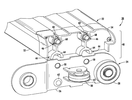
Referring now to the drawings and the illustrative embodiments depicted
therein, a positive displacement sorter 20 includes a plurality of parallel
laterally
-4-
CA 02858124 2014-06-03
WO 2013/096011
PCT/US2012/068968
extending slats 22 and a pair of wheel assemblies 24. Each wheel assembly
interconnects common end portions of slats 22 thereby defining an endless web
32 that
travels in a longitudinal direction, shown as the direction of travel in Fig.
1. It should
be understood that the other wheel assembly (Fig. 5a) is a minor image of the
one
shown in Fig. 5b and interconnects the opposite end portions of the slats. An
upper
surface of web 32 defines an article-conveying surface 34. A plurality of
pusher shoes
36 each travel along one or more of slats 22 in order to laterally displace
articles (not
shown) on conveying surface 34. Sorter 20 includes a propulsion device for web
32,
diverting gates and rails for pusher shoes 36.
Each wheel assembly 24 includes a plurality of interconnected vertical link
plates 26, each associated with one slat 22, vertical wheels 28 that allow
endless web 32
to travel in the longitudinal direction and a plurality of horizontal side
thrust wheels 30
that resist lateral, or sideward, movement of endless web 32. Link plates 26
are
interconnected by the axles for vertical wheels 28. A cover, such as a capture
angle 38,
covers wheel assembly 24 and restrains vertical wheels 28 from rising
significantly
above their lower support surface 39. It should be understood that the
techniques
disclosed herein are equally useful with sorter wheel assemblies utilizing
chains
connected with the slats to propel the web.
Sorter 20 includes a plurality of attachment mechanisms 40, each attaching an
end portion of one of slats 22 to one of wheel assemblies 24. Each of
attachment
mechanisms 40 includes a shoulder, generally shown at 42, a collar, generally
shown at
44 and at least one locking member generally shown at 46. As will be explained
in
more detail below, collar 44 engages shoulder 42 thereby providing retention
of an end
of a slat 22 to said one of wheel assemblies 24 while locking member(s) 46
provides
retention of collar 44 on shoulder 42. In the illustrated embodiment, locking
member
46 includes a generally horizontally moveable elongated member 48 that engages
an
opening 50 in order to retain collar 44 on shoulder 42, particularly when the
slat is
either travelling upside down or experiencing centripetal forces when rounding
an end
of the sorter. Otherwise, shoulder 42 on collar 44 provides sufficient
strength to carry
the load on the slat from articles being sorted by sorter 20 on article-
conveying surface
34, by a maintenance technician standing on article-conveying surface 34, or
the like.
-5-
CA 02858124 2014-06-03
WO 2013/096011
PCT/US2012/068968
In the illustrated embodiment, locking member(s) 46 are on slat 22 and
openings 50
being defined in a corresponding link plate 26 of one of wheel assemblies 24.
However, it may be possible to provide locking member 46 on link plate 26
engaging an
opening 50 on the slat.
Shoulder 42 is on either wheel assembly 24, with collar 42 on slat 22, or
vice versa. In the illustrated embodiment, shoulder 42 is mounted to a link
plate 26 of a
wheel assembly 24 and collar 44 is on slat 22. In this manner, collar 44 and
opening(s)
50 provide a wheel assembly portion of attachment mechanism 40, while collar
44 and
elongated member(s) 48 define a slat portion of attachment mechanism 40. In
the
illustrated embodiment, a vertical link plate 26 is provided at each of said
slats and has
set of through-holes 51 that are provided to mount collar 44. Through-holes 51
are
symmetrical with opening(s) 50. This provides a common configuration of
vertical
plate 26 which can be used in both wheel assemblies merely by reversing the
plates, as
would be apparent to the skilled artisan.
Each slat 22 is made up of an elongated extrusion 52, such as an aluminum
extrusion made by commonly available extrusion or pul-trusion techniques, and
a
generally polymeric slat extension 54 engaging the end portion of elongated
extrusion
52, wherein elongated member(s) 48 and collar 44 are a part of slat extension
54.
In the illustrated embodiment, shoulder 42 is made up two or more spaced apart
horizontally extending studs 62 and collar 44 is made up of a corresponding
number of
sockets 64 that are configured to engage studs 62. Each stud 62 is circular in
cross
section and includes an enlarged head 66. Each stud 62 may be rigidly
connected with
its through-hole 51 by swaging, welding, or the like, as best seen in Fig. 9.
Sockets 64
define a semi-circular recess that fits over enlarged head 66 in order to
laterally retain
the corresponding one of sockets 64 on that stud. In this manner, the
engagement
between shoulder 42 and collar 44 carries the weight of the slats and any load
placed on
article-conveying surface 34 and resists any lateral forces tending to
separate the slat
laterally from the wheel assembly. In this manner, the function of locking
member 46
is to carry the weight of the slat when at a lower run of web 32 or at a
transition
between upper and lower runs of the web at the ends of sorter 20, as well as
to ensure
that collar 44 is kept in engagement with shoulder 42.
-6-
CA 02858124 2014-06-03
WO 2013/096011
PCT/US2012/068968
Elongated member(s) 48 is generally laterally moveable with respect to slats
22
in order to engage opening(s) 50. As best seen in Fig. 10, in the illustrated
embodiment,
each elongated member 48 is made up of a pin 68 and a biasing mechanism, such
as a
compression spring 70 that biases pin 68 into engagement with opening 50. A
retention
fastener 72 passes through an opening in a neck 76 of a cylinder 74, in which
both pin
68 and biasing mechanism 70 reside, and engages pin 68 to retain the pin in
cylinder 74
against the bias of biasing mechanism 70.
Pins 68 may be retracted by a variety of techniques in order to either
separate a
slat 22 from wheel assemblies 24 or return the slat to the mounted
configuration. In the
illustrated embodiment, slat extension 54 is made almost entirely from a
structural
plastic such as polypro long glass reinforced polymer that is formed by
molding,
although other materials may be used. Pins 68 move in bronze sleeves 69 to
provide
durability and lubrication. Pins 68 have tapered ends which taper such that
the diameter
at a distal end is less than the diameter of openings 50 and increase in
diameter inwardly
to a proximal diameter that forms an interference fit with openings 50. This
provides
ease of insertion of the pins while ensuring a movement-free attachment of the
slats to
the wheel assembly. Also, each pin 68 includes a dimple 69 at its end for
engagement
by a pin retraction tool 80.
Pin retraction tool 80 actuates the pins 68 from outside of link plate 26 of
wheel
assembly 24 (Fig. 11). Also, retraction tool 80 is configured to retract two
pins at a
time, but could be configured to retract one pin at a time. Pin retraction
tool 80 includes
a handle 92 at one end and an engagement end 83 that is configured to engage
the ends
of two pins 68. Retraction tool 80 additionally includes a pivot 85. Pivot 85
pivots
against link plate 26 in an indent or recess 82 in slat 22. Recess 82 allows
pivot 85 to
sufficiently engage the inner surface of link plate 26 in order to have
sufficient leverage
to compress pins 68. However, recess 82 does not need to open into the
interior of slat
extension 54 so does not provide a conduit for debris to enter the slat
extension. Tool
80 additionally includes a finger 87 to retract a pin 68.
In use, the operator rests pivot 85 against link plate 26 in recess 82, which
aligns
engaging end 83 with the corresponding pin 68 as shown in Figs 12 and 15. The
operator then pivots handle 92 laterally outwardly, as seen in Figs. 13 and 16
which
-7-
CA 02858124 2014-06-03
WO 2013/096011
PCT/US2012/068968
retracts the pin, thereby allowing that end of the slat to be elevated
sufficiently for the
pin to move past opening 50 so that it stays retracted against the link plate.
This process
is repeated for the other end of the slat. The slat can then be removed by
lifting
upwardly. An end of handle 92 could have a tapered end 93 in order to compress
a pin
against link plate 126 to reinstall the slat, as seen in Figs. 14 and 17. It
should be
apparent from the illustrations in Figs. 12-17 that the slat can be removed by
inserting
pin retraction tool 80 between link plate 26 and cover or cap angle 38.
Therefore, the
slat can be removed without removing cover 38.
While the foregoing description describes several embodiments of the present
invention, it will be understood by those skilled in the art that variations
and
modifications to these embodiments may be made without departing from the
spirit and
scope of the invention, as defined in the claims below. The present invention
encompasses all combinations of various embodiments or aspects of the
invention
described herein. It is understood that any and all embodiments of the present
invention
may be taken in conjunction with any other embodiment to describe additional
embodiments of the present invention. Furthermore, any elements of an
embodiment
may be combined with any and all other elements of any of the embodiments to
describe additional embodiments.
-8-