Note: Descriptions are shown in the official language in which they were submitted.
CA 02858260 2014-08-01
SYSTEMS, ASSEMBLIES AND PROCESSES FOR CONTROLLING TOOLS IN A
WELL BORE
This application is a divisional of Canadian Patent Application No. 2,717,198,
filed March 4, 2009.
BACKGROUND OF THE INVENTION
FIELD OF THE INVENTION:
The present invention relates to systems, assemblies and processes for
controlling equipment, tools and the like that are positioned in a
subterranean well bore,
and more particularly, to systems, assemblies and processes for controlling a
plurality of
equipment, tools and the like that are positioned in a subterranean well bore.
DESCRIPTION OF RELATED ART:
In the production of fluid from subterranean environs, a well bore is drilled
so as
to penetrate one or more subterranean zone(s), horizon(s) and/or formation(s).
The
well is typically completed by positioning casing which can be made up of
tubular joints
into the well bore and securing the casing therein by any suitable means, such
as
cement positioned between the casing and the walls of the well bore.
Thereafter, the
well is usually completed by conveying a perforating gun or other means of
penetrating
casing adjacent the zone(s), horizon(s) and/or formation(s) of interest and
detonating
explosive charges so as to perforate both the casing and the zone(s),
horizon(s) and/or
formation(s). In this manner, fluid communication is established between the
zone(s),
horizon(s) and/or formation(s) and the interior of the casing to permit the
flow of fluid
from the zone(s), horizon(s) and/or formation(s) into the well. Alternatively,
the well can
be completed as an "open hole", meaning that casing is installed in the well
bore but
terminates above the subterranean environs of interest. The well is
subsequently
equipped with production tubing and convention associated equipment so as to
produce
fluid from the zone(s), horizon(s) and/or formation(s) of interest to the
surface. The
1
CA 02858260 2014-08-01
casing and/or tubing can also be used to inject fluid into the well to assist
in production
of fluid therefrom or into the zone(s), horizon(s) and/or formation(s) to
assist in
extracting fluid therefrom.
Often during the drilling and completion of a well or during production or
injection
of fluid from or into a well or subterranean environs, it can be desirable to
control the
operation of multiple tools, equipment, or the like, for example perforating
guns, cutters,
packers, valves, sleeves, etc., that can be positioned in a well. In the
production of fluid
from or injection of fluid into subterranean environs, multiple tools and
equipment are
often positioned and operated in a well bore. For example, a plurality of
perforating
guns can be deployed within a well bore to provide fluid communication between
multiple zones, horizons and/or formations. Upon detonation, these guns file
projectiles
through casing cemented within the well bore to form perforations and
establish fluid
communication between the formation and the well bore. Often these perforating
guns
are detonated in sequence. A plurality of flapper valves can be used in
conjunction with
multiple perforating guns to isolate the zone, horizon or formation being
completed from
other zones, horizons and/or formations encountered by the well bore. As
another
example, packers can be deployed on a tubular and expanded into contact with
casing
to provide a fluid tight seal in the annulus defined between the tubular and
the casing.
Flow chokes can be used to produce the well from multiple zones with these
chokes set
at different openings to balance the pressure existing between multiple
subterranean
zones, horizons and/or formations so that a plurality of such zones, horizons
and/or
formations can be produced simultaneously.
Hydraulic systems have been used to control the operation of tools positioned
in
a well. Such systems have a control system and a down hole valve. The control
system includes surface equipment, such as a hydraulic tank, pump, filtration,
valves
and instrumentation, control lines, clamps for the control lines, and one or
more
hydraulic controller units. The control lines run from the surface equipment
to and
through the wellhead and tubing hanger to desired equipment and tools in the
well.
These control lines are clamped usually along a tubular that is positioned
within a well.
The control lines can be connected to one or more hydraulic control units
within a well
2
CA 02858260 2014-08-01
for distributing hydraulic fluid to the down hole valves.
Several basic arrangements of hydraulic control lines are used in a well. In a
direct hydraulic arrangement, each tool that is to be controlled will have two
dedicated
hydraulic lines. The "open" line extends from the surface equipment to the
tool and is
used for transporting hydraulic fluid to the downhole control valve to operate
the tool,
while the "close" line extends from the tool to the surface equipment and
provides a
path for returning hydraulic fluid to the surface of the earth. The practical
limit to the
number of tools that can be controlled using the direct hydraulic arrangement
is three,
i.e. six separate hydraulic lines, due to the physical restraints in
positioning hydraulic
lines in a well. The tubing hanger through which the hydraulic lines run also
has to
accommodate lines for a gauge system, at least one safety valve and often a
chemical
injection line, which limits the number of hyraulic lines the hanger can
accommodate.
When it is desirable to control more than three tools in a well, a common
close
arrangement can be employed in which an open line is run to each tool to be
controlled
and a common close line is connected to each tool to return hydraulic fluid to
the
surface. Again, the common close system has a practical limit of controlling
five tools,
i.e. six separate hydraulic lines.
In another arrangement, a single hydraulic line is dedicated to each tool and
is
connected to each tool via a separate, dedicated controller for each tool. To
open the
tool, the hydraulic fluid in the dedicated line is pressurized to a first
level. Thereafter,
the hydraulic fluid in the dedicated line is pressurized to a higher level so
as to close the
tool. In a digital hydraulics system, two hydraulic lines are run from the
surface
equipment to a downhole controller that is connected to each of the tools to
be
controlled. Each controller is programmed to operate upon receiving a
distinct
sequence of pressure pulses received through these two hydraulic lines. Each
tool has
another hydraulic line is connected thereto as a common return for hydraulic
fluid to the
surface. The controllers employed in the single line and the digital
hydraulics
arrangements are complex devices incorporating numerous elastomeric seals and
springs which are subject to failure. In addition, these controllers use
small, inline filters
to remove particles from the hydraulic fluid that might otherwise contaminate
the
3
CA 02858260 2014-08-01
controllers. These filters are prone to clogging and collapsing. Further, the
complex
nature of the pressure sequences requires a computer operated pump and valve
manifold which is expensive.
In accordance with the "distribution hub" arrangement, two hydraulic lines are
run
from the surface to one downhole controller to which each tool to be
controlled is
connected by its own set of two hydraulic lines. This controller can be
ratcheted to any
of a number of predetermined locations, each of which connects the control
lines of a
given tool to the control lines running from the surface to the controller. In
this manner,
each tool can be operated independently from the surface. By ratcheting the
controller
to another location, another tool can be operated. This arrangement is
expensive due
to the large number of components and complex arrangement of seals in the
controller
and unreliable as it is difficult to get feedback to the surface on the exact
position of the
controller, especially if the operator has lost track of the pulses previously
applied.
Thus, a need exists for hydraulic control systems, assemblies and processes
for use in
controlling multiple tools in a well which is relatively inexpensive, simple
in construction
and operation and reliable.
Further, it is often desirable to stimulate the subterranean environs of
interest to
enhance production of fluids, such as hydrocarbons, therefrom by pumping fluid
under
pressure into the well and the surrounding subterranean environs of interest
to induce
hydraulic fracturing thereof. Thereafter, fluid can be produced from the
subterranean
environs of interest, into the well bore and through the production tubing
and/or casing
string to the surface of the earth. Where it is desired to stimulate or
fracture the
subterranean environs of interest at multiple, spaced apart locations along a
well bore
penetrating the environs, fluid is pumped into a particular location adjacent
the
subterranean environs of interest that is farthest from the surface of earth
while a
means, such as a flapper valve(s), is employed to isolate the remaining
locations. Once
fluid is pumped under pressure from the surface into the well and the
lowermost
location, means are actuated to isolate the next location which is closest to
the surface
from the lowermost location and the remaining locations. Fluid is pumped under
pressure from the surface into the well and the subterranean environs adjacent
the
4
CA 02858260 2014-08-01
isolated location so as to hydraulically fracture the same. In this manner,
all of the
subterranean environs adjacent to the multiple, spaced apart locations can be
hydraulically fractured in sequence beginning at the location that is farthest
from the
surface along the well bore. Conventional systems and associated methodology
that
are used to stimulate subterranean environs in this manner include casing
conveyed
perforating systems, ball drop systems, and perforate and plug systems.
However, problems exist with hydraulically fracturing subterranean environs
from
multiple, spaced apart locations in sequence beginning with location that is
farthest from
the surface along the well bore. Hydraulic fracturing of subterranean environs
creates
stress forces in rock that essentially harden the particular regions of the
subterranean
formation fractured thereby inhibiting propagation of fractures created during
hydraulic
fracturing of an adjacent region into the region previously fractured. This
can cause
hydraulic fractures formed in the adjacent region to propagate away from the
previously
fractured region which may not be desirable. Accordingly, a need exists for a
process
for sequentially fracturing subterranean environs from spaced apart locations
along the
well bore in any desired sequence. A further need exists for a process for
sequentially
fracturing subterranean environs from spaced apart locations along the well
bore in a
sequence calculated to advantageously use rock stress generated in the
subterranean
environs to propagate fractures in a desired manner.
SUMMARY OF THE INVENTION
To achieve the foregoing and other objects, and in accordance with the
purposes
of the present invention, as embodied and broadly described herein, one
characterization of the present invention is a hydraulic control system for
use in a
subterranean well is provided. The control system comprises a control line
positioned in
a subterranean well and extending adjacent at least one tool positioned within
the
subterranean well. The control line is sized to permit passage of a control
device and
each of the at least one tool has a reader device connected thereto.
5
CA 02858260 2014-08-01
In another characterization of the present invention, a process is provided
for
conveying at least one control device capable of generating one or more unique
signals
through a control line positioned in a subterranean well so as to control the
operation of
at least one tool positioned in the well outside of the control line.
In yet another characterization of the present invention, a process is
provided for
conveying hydraulic fluid via a first hydraulic line to at least one tool
positioned in a
subterranean well to control the operation of the tool. At least one control
device is
conveyed through a control line positioned in the well and outside of the
first hydraulic
line and the at least one tool. Each of the at least one control device is
capable of
generating one or more unique signals for controlling flow of hydraulic fluid
from the first
hydraulic line to the at least one tool.
In a further characterization of the present invention, a process is provided
for
fracturing a subterranean environs penetrated by a well at spaced apart
locations along
the well using tools that remain in the well. The sequence of fracturing
comprises
fracturing the subterranean environs at one of the spaced apart locations
after fracturing
the subterranean environs at another of the spaced apart locations which is
closer to
the surface of the earth along the well.
In a still further characterization of the present invention, a process is
provided
that comprises pumping fluid through casing positioned in a well and an
opening in a
first tool secured to the casing at a pressure sufficient to fracture a
portion of a
subterranean environs. Thereafter, fluid is pumped through the casing and an
opening
in a second tool secured to the casing at a pressure sufficient to fracture
another portion
of the subterranean environs. The second tool is farther along the well from
the surface
of the earth than the first tool.
In yet a still further characterization of the present invention, a process is
provided that comprises fracturing a first portion of a subterranean environs
penetrated
by a well at a first location along the well using tools that remain in the
well. Fracturing
of the first portion creates rock stress within the first portion. A second
portion of said
subterranean environs is fractured at a second location along the well using
the tools
6
CA 02858260 2015-04-02
which results in fractures in the second portion that have a geometry
influenced by the
rock stress present in the first portion.
BRIEF DESCRIPTION OF THE DRAWINGS
The accompanying drawings, which are incorporated in and form a part of the
specification, illustrate the embodiments of the present invention and,
together with the
description, serve to explain the principles of the invention.
In the drawings:
FIG. 1A is a schematic view of one embodiment of the systems and assemblies
of the present invention that utilizes a dedicated control line;
FIG. 1B is a sectional view of a hydraulic control line of FIG. 1A having a
signal
device therein;
FIG. 2A is a schematic view of another embodiment of the systems and
assemblies of the present invention that utilizes three hydraulic lines that
extend to the
surface;
FIG. 2B is a sectional view of a hydraulic control line of FIG. 2A having a
signal
device therein;
FIG. 3A is a schematic view of a further embodiment of the systems and
assemblies of the present invention that utilizes two hydraulic lines that
extend to the
surface;
FIG. 3B is a sectional view of a hydraulic control line of FIG. 3A having a
signal
device therein;
FIG. 4A is a schematic view of still further embodiment of systems and
assemblies of the present invention that utilizes one hydraulic line that
extends to the
surface;
FIG. 4B is a sectional view of a hydraulic control line of FIG. 4A having a
signal
device therein;
FIG. 5A is a partially cross sectional illustration of the embodiment of the
present
invention that utilizes three hydraulic lines as deployed in a subterranean
well; and
7
CA 02858260 2014-08-01
FIG. 5B is a sectional view of the hydraulic control lien of FIG. 5A having a
signal
device therein.
DETAILED DESCRIPTION OF THE PREFERRED EMBODIMENTS
As utilized throughout this description, the term "signal control line" refers
to a
continuous or jointed line, conduit, tubular or similar structure for
conveying fluid and a
control device. The substantially axial bore through the control line is
sufficient to permit
passage of a control device therethrough but the outside diameter of the
control line is
sufficiently small so as not to impede placement of other lines, tubulars,
tools and
equipment within the well. A nonlimiting example of suitable diameters for a
signal
control line are an outside diameter of from about 0.25 inch to about 0.50
inch and a
substantially axial bore diameter of from about 0.15 inch to about 0.40 inch.
The
diameter of the substantially axial bore through the signal control line used
in
accordance with the present invention is not sufficient to allow commercial
quantities of
formation fluids to be produced therethrough. The signal control line can be
constructed
of any suitable material, for example stainless steel or a stainless steel
alloy. A "signal
device" refers to a device which is capable of generating one or more unique
signals.
Nonlimiting examples of a signal device are a radio frequency identification
device
(RFID), a device carrying a magnetic bar code, a radioactive device, an
acoustic device,
a surface acoustic wave (SAW) device, a low frequency magnetic transmitter and
any
other device that is capable of generating one or more unique signals. The
signal
device can have any suitable peripheral configuration and geometric shape, and
is
sized to permit conveyance through the signal control line. Some signal
devices, for
example RFID, can require a peripheral configuration and geometric shape to
inhibit
tumbling of the RFID during conveyance through the signal control line. A
suitable
RFID is commercially available from Sokymat SA, Switzerland under the trade
name
"Glass Tag 8 mm Q5". A "reader device" refers to a device capable of
transmitting
signals to and receiving signals from a signal device.
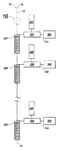
In accordance with one embodiment of the present invention as illustrated in
FIG.
1, a signal control line 14 can be positioned in a subterranean well and
extend from the
8
CA 02858260 2015-04-02
well head 10 to a position at least adjacent to the most remote tool from the
well head
that is desired to be controlled by the processes of the present invention.
Signal control
line 14 has a first end 16 at or near the well head 10 and a second end 18
located in the
well. Although signal control line 14 can be supported from the well head and
unattached as positioned in the well, it is preferably secured to tubulars
and/or tools
positioned in a well by any suitable means, for example by clamps, and can be
armored
as will be evident to a skilled artisan. Signal control line can be open at
end 18 thereof
to the well bore. One or more tools or equipment 30A, 30B and 30N can be
positioned
in a well and can be connected to reader devices 20A, 20B and 20N,
respectively.
Tools 30A, 30B and 30N can be connected to the associated reader devices 20A,
20B
and 20N by any suitable means, such as via a hydraulic or electric line or
acoustic
connection 31A, 31B and 31N. Each reader device is connected to a suitable
power
source 24A, 24B, and 24N and antennas 22A, 22B and 22N, respectively.
Nonlimiting
examples of suitable power sources are batteries. As illustrated, antennas 22
can be
coiled to surround control line 10 such that the orientation of signal device
12 within
control line 10 is immaterial to the reception of a signal by antenna 22. An
unlimited
number of tools 30 can be controlled by the present invention, with the total
number of
tools that are positioned in a well and capable of being controlled by the
present
invention being designated by the letter "N".
In operation, a suitable signal device 12 can be conveyed from the well head
10
through line 14, for example in suitable fluid, such as hydraulic oil or
water, that can be
pumped by equipment located at the surface. The signal device 12 is sized and
configured to inhibit the signal device from tumbling in line 14 during
conveyance (FIG.
1B). Each signal device 12 is programmed to generate a unique signal.
Similarly, each
reader device 20A, 20B and 20N is programmed to look for a unique code signal.
As
the signal device 12 passes in proximity to a reader device 20, the unique
signal
transmitted by signal device 12 can be received by an antenna 22. If a given
reader
device 20 is programmed to respond to the signal transmitted by the device 12
via the
associated antenna 22, the reader device 20 transmits a corresponding control
signal to
9
CA 02858260 2015-04-02
the associated tool 30 to actuate the tool. Reader devices 20 can also
transmit signals
which in turn are received by and cause signal device 12 to generate the
unique signal.
Each reader device 20 can be programmed to respond to its own unique signal
or the same signal of at least one other reader device. As the signal device
12 is
conveyed through line 14, the unique signal transmitted thereby can be
received and
read by each successive reader device. If the unique signal matches that
programmed
in the reader device, the reader device transmits a control signal to actuate
the
associated tool 30. Ultimately, the signal device 12 exits through the end of
the control
line 14 into the well. Thereafter, one or more additional control devices can
be
conveyed via control line 14 to actuate one or more tools 30 in any sequence
and
manner desired. In this manner, an unlimited number of tools can be actuated
by
conveying one or more control devices via control line 14. When line 14 is
open at end
18 to the well bore, it is subject to hydrostatic fluid, and as such, the
hydraulic pressure
exerted in this line must be sufficient to overcome this pressure so as to
convey signal
device 12 through line 14.
In accordance with another embodiment of the present invention as illustrated
in
Fig. 2, three hydraulic lines 114, 154 and 164 can be positioned in a
subterranean well
and extend from the well head 110 to a position at least adjacent to the most
remote
tool from the well head that is desired to be controlled by means of this
embodiment of
the present invention. Each line 114, 154 and 164 has a first end 116, 156,
166,
respectively, at or near the well head 110 and a second end 118, 158 and 168
located
in the well. Second end 118 or line 114 can be open to the well and therefore
the
hydrostatic pressure of any fluid that is present in the well, while ends 158
and 168 of
lines 156 and 166, respectively, can be capped or plugged as illustrated in
FIG. 1 by
any suitable means as will be evident to a skilled artisan. Alternatively, the
end 116 of
control line 114 can be connected to either end 158 of control line 154 or end
168 of
control line 164 to permit the control device 112 to be conveyed through line
114 and
back to the surface through line 154 or line 164. Although lines 116, 156 and
166 can
be supported from the well head and unattached as positioned in the well, each
line is
CA 02858260 2015-04-02
=
preferably secured to tubulars and/or tools positioned in a well by any
suitable means,
for example by clamps, and can be armored as will be evident to a skilled
artisan.
A plurality of tools or equipment 130A, 130B and 130N are positioned in a well
and can have a piston or sleeve 132A, 132B and 132N, respectively, moveably
secured
therein. Each tool 130A, 130B and 130N can be connected to hydraulic line 154
by
means of lines 134A, 134B and 134N, respectively, each of which has a
corresponding
valve 136A, 136B and 136N. Each tool 130A, 130B and 130N can also be connected
to
hydraulic line 164 by means of lines 138A, 138B and 138N, respectively. Reader
devices 120A, 120B and 120N are electrically connected to a suitable power
source
124A, 124B, and 124N and antennas 122A, 122B and 122N, respectively.
Nonlimiting
examples of suitable power sources are batteries. These power sources can be
preprogrammed to be in a sleep mode except for certain predetermined periods
of time
so as to conserve power consumption and therefore extend the life of the power
source.
As illustrated antennas 122A, 122B and 122N are coiled to surround control
line 114
such that the orientation of the signal device 112 within control line 114 is
immaterial.
Each reader device 120A, 120B and 120N can be electrically connected to
corresponding motors 126A, 126B and 126N, respectively, which in turn drive
shaft or
stem 127A, 127B and 127N to open or close valves 136A, 136B and 136N as will
be
evident to a skilled artisan. An unlimited number of tools 130 can be
controlled by this
embodiment of the present invention, with the total number of tools that are
positioned
in a well and capable of being controlled being designated by the letter "N".
Hydraulic
fluid, such as hydraulic oil or water, can be used in each of the three
hydraulic lines and
can be pressurized by any suitable means, such as a pump located at or near
the well
head, to a pressure sufficient to overcome the hydrostatic pressure of fluid
present in
the well to move from the well head through fluid and signal device 112 a
hydraulic line
and into the well.
As typically positioned in a well, valves 136A, 136B and 136 N are in a closed
positioned and pistons 132A, 132B and 132N are positioned to one end of the
respective tool 130 as noted by the positions x or y in Fig. 2. While the
tools 130 are
illustrated in Fig. 2 as having a position generally on each end and in the
center of the
11
CA 02858260 2015-04-02
tool, the piston can be able to achieve several positions along the tool and
have an
associated mechanism, such as a collet, to allow this to be accomplished. A
nonlimiting
example of a tool utilizing a piston having variable positions is a variable
choke installed
in a tubular positioned in a well.
1 1 a
CA 02858260 2014-08-01
In operation, a suitable signal device 112 can be conveyed from the well head
110 through line 114, for example in fluid pumped by equipment located at the
surface.
Each signal device 112 is programmed to generate a unique signal. Similarly,
each
reader device 120A, 120B and 120N is programmed to look for a unique code
signal.
As the signal device 112 passes in proximity to a given reader device 120, the
unique
signal transmitted by signal device 112 can be received by an antenna 122. If
a given
reader device 120 is programmed to respond to the signal transmitted by the
device 112
via the associated antenna 122, the reader device 120 transmits a
corresponding
control signal to the associated motor 126 which in turn causes valve 136 to
open via
shaft 127. Reader devices 120 can also transmit signals which in turn are
received by
and cause signal device 112 to generate the unique signal. As hydraulic fluid
in line
154 is thereby permitted to flow through line 134 and valve 136, the pressure
of the
hydraulic fluid causes piston 132 in tool 130 to move to the desired position
and thereby
actuate the tool. Movement of the piston 132 in tool 130 causes the hydraulic
fluid on
the other side of piston 132 to flow back to the well head 110 via hydraulic
line 164. To
move piston 132 to a different position, pressure on the hydraulic fluid in
line 154 or line
164 can be increased to move the piston with the associated mechanism, such as
a
collet, thereby permitting the piston to sequentially achieve several
positions along the
tool 130.
Each reader device 120 can be programmed to respond to its own unique signal
or the same signal of at least one other reader device. As the signal device
112 is
conveyed through line 114, the unique signal transmitted thereby can be
received and
read by each successive reader device. If the unique signal matches that
programmed
in the reader device, the reader device transmits a control signal to open the
associated
motor 126 and valve 136. Ultimately, the signal device 112 exits through the
end of the
control line 114 into the well. Thereafter, one or more additional signal
devices 112 can
be conveyed via control line 114 to actuate one or more motor(s) 126 and
valve(s) 136
in any sequence and manner desired. In this manner, an unlimited number of
tools 130
can be actuated by conveying one or more control devices via control line 114.
As line
114 is open at end 118 to the well bore, it is subject to hydrostatic fluid
and as such the
12
CA 02858260 2014-08-01
hydraulic pressure exerted in this line must be sufficient to overcome this
pressure so
as to convey signal device 112. Alternatively, line 114 can be connected to
line 158
thereby permitting passage of signal device 112 to the surface. Signal device
112 can
be configured to receive a signal from a given reader device that the unique
signal
conveyed by the signal device was received by the reader device. In this
instance, the
reader devices 120 are transceivers permitting each device to receive a unique
signal
from the signal device and to transmit another unique signal back to the
signal device.
Each signal device 112 can also be equipped with suitable gauges to measure
well,
formation, and/or fluid conditions which can then be recorded in signal device
112.
Nonlimiting examples of suitable gauges are temperature and pressure gauges.
Information contained in the signal device 112 can be read at the surface,
erased from
the signal device 112, if desired, and the signal device can be programmed to
emit
another unique signal for use in the same well or another well.
To close each valve 136, each associated reader device can be preprogrammed
to actuate the appropriate motor 126 and shaft 127 after a period of time to
close the
associated valve 136. Alternatively, a signal device 112 can be conveyed via
line 114
to transmit a unique signal to the appropriate reader device 120 via antenna
122 which
in turn transmits a corresponding control signal to the associated motor 126
causing
shaft 127 to close valve 136.
In accordance with another embodiment of the present invention as illustrated
in
Fig. 3, two hydraulic lines 214 and 264 are positioned in a subterranean well
and extend
from the well head 110 to a position at least adjacent to the most remote tool
from the
well head that is desired to be controlled by means of this embodiment of the
present
invention. Lines 214 and 264 have a first end 216 and 266, respectively, at or
near the
well head 210 and a second end 218 and 268 secured and in fluid communication
with
a line 270. Although lines 216 and 266 can be supported from the well head and
unattached as positioned in the well, each line, including line 270, is
preferably secured
to tubulars and/or tools positioned in a well by any suitable means, for
example by
clamps, and can be armored as will be evident to a skilled artisan.
13
CA 02858260 2015-04-02
In the embodiment of the present invention illustrated in Fig. 3, each tool
230A,
230B and 230N can be connected to hydraulic line 214 by means of lines 234A,
234B
and 234N, respectively, each of which has a corresponding valve 236A, 236B and
236N. Each tool 230A, 230B and 230N can also be connected to hydraulic line
164 by
means of lines 138A, 138B and 138N, respectively. Valves 236A, 236B and 236N
are
initially in the closed position as the system is deployed in a well, while
valve 290 in line
270 connecting the lower ends of 218, 268 of lines 214 and 264 together is
initially in
the open position. To begin operation, a unique signal device 212 can be
conveyed via
line 214 by any suitable means, for example hydraulic oil. The unique signal
transmitted
by signal device 212 can be received by each antenna 222A, 222B and 222N and
conveyed to each associated reader device 220A, 220B and 220N. If a given
reader
device has been preprogrammed to respond to the received signal, that reader
device
actuates at least one motor 226A, 226B or 226N to open the associated valve
236A,
236B or 236N via the appropriate shaft 227A, 227B or 227N. The signal device
then
passes through line 270 and conveys a signal to reader device 280 via antenna
282.
Reader device 280, which can be powered by power source 284, in turn activates
motor
296 to close valve 290 via shaft 297. Each signal device can be configured to
receive a
signal from a given reader device that the unique signal conveyed by the
signal device
was received by the reader device. In this instance, the reader devices 220
are
transceivers permitting each device to receive a unique signal from the signal
device
and to transmit another unique signal back to the signal device. Each signal
device 212
can also be equipped with suitable gauges to measure well, formation, and/or
fluid
conditions which can then be recorded in signal device 212. Nonlimiting
examples of
suitable gauges are temperature and pressure gauges. With valve 290 closed,
hydraulic
fluid can be directed via line 214 to that valve(s) 236 that was opened by the
unique
signal device 212 to move piston 232 to a desired position. Valves 236A, 236B
and
236N are in a closed positioned and pistons 232A, 232B and 232N are positioned
to
one end of the respective tool 230A, 230B and 230N as noted by the positions x
or y in
Fig. 3. While the tools 230 are illustrated in Fig. 3 as having a position
generally on
each end and in the center of the tool, the piston can be able to achieve
several
14
CA 02858260 2015-04-02
positions along the tool and have an associated mechanism, such as a collet,
to allow
this to be achieved. Reader device 280 can be programmed to cause valve 290 to
open a predetermined time after being closed or the unique signal(s) from
signal device
212 can contain instructions to cause the reader device to open valve 290 in a
predetermined amount of time. Once valve 290 is open, signal device 212 can be
conveyed to the well head 210 via line 264 by pressurizing hydraulic
14a
CA 02858260 2014-08-01
fluid in line 214. Information contained in the signal device 212 can be read
at the
surface, erased from the signal device 212, if desired, and the signal device
can be
programmed to emit another unique signal for use in the same well or another
well.
In the embodiment of the present invention illustrated in Fig. 4, one
hydraulic line
314 can be positioned in a subterranean well and extends from the well head
310 to a
position at least adjacent to the most remote tool from the well head that is
desired to be
controlled by means of this embodiment of the present invention. Line 314 has
a first
end 316 at or near the well head 310 and a second end 318 open to the well.
Hydraulic
line 314 is also equipped with a valve 390 which is initially in an open
position.
Although line 314 can be supported from the well head and unattached as
positioned in
the well, line 314 is preferably secured to tubulars and/or tools positioned
in a well by
any suitable means, for example by clamps, and can be armored as will be
evident to a
skilled artisan. One or more tools 330 are positioned in the well by means of
continuous
or jointed tubulars or wireline. The letter "N" represents the total number of
tools and
associated equipment that are positioned in the well and assembled as capable
of being
controlled in accordance with the system and process of this embodiment of the
present
invention. Tools 330 are connected to hydraulic line 314 by means of
associated
hydraulic lines 334 and have pistons 332 positioned therein. Pistons 332A,
332B and
332N are positioned to one end of the respective tool 330 as noted by the
positions x or
y in Fig. 4. While the tools 330 are illustrated in Fig. 4 as having a
position generally on
each end and in the center of the tool, the piston can be able to achieve
several
positions along the tool and have an associated mechanism, such as a collet,
to allow
this to be achieved. A nonlimiting example of a tool utilizing a piston having
variable
positions is a variable choke installed in a tubular positioned in a well.
Change-over valves 336 are positioned in hydraulic lines 334 and are connected
to and controlled by motors 326 and shafts 327. Reader devices 320A, 320B and
320N
are electrically connected to a suitable power source 324A, 324B, and 324N and
antennas 322A, 322B and 322N, respectively. Nonlimiting examples of suitable
power
sources are batteries. These power sources can be preprogrammed to be in a
sleep
mode except for certain predetermined periods of time so as to conserve power
CA 02858260 2014-08-01
consumption and therefore extend the life of the power source. As illustrated,
antennas
322A, 322B and 322N are coiled to surround control line 314 such that the
orientation of
the signal device 312 within control line 314 is immaterial. Each reader
device 320A,
320B and 320N is electrically connected to corresponding motors 326A, 326B and
326N, respectively, which in turn drive shaft or stem 327A, 327B and 327N to
open or
close valves 336A, 336B and 336N as will be evident to a skilled artisan.
Another reader device 380 is electrically connected to a suitable power source
384 and antenna 382 which is configured to surround hydraulic line 314. Reader
device
380 is also electrically connected to motors 396 which drives shaft or stem
397 to open
or close valve 390 as will be evident to a skilled artisan.
In operation, a signal device 312 can be conveyed via line 314, through open
valve 390 and open end 318 into the well for example in fluid pumped by
equipment
located at the surface. Each signal device 312 is programmed to generate a
unique
signal. Similarly, each reader device 320A, 320B and 320N is programmed to
look for a
unique code signal. As the signal device 312 passes in proximity to a given
reader
device 320, the unique signal transmitted by signal device 312 can be received
by an
antenna 322. If a given reader device 320 is programmed to respond to the
signal
transmitted by the device 312 via the associated antenna 322, the reader
device 320
transmits a corresponding control signal to the associated motor 326 which in
turn
causes valve 336 to open via shaft 327. Reader devices 320 can also transmit
signals
which in turn are received by and cause signal device 312 to generate the
unique
signal. Antenna 382 conveys a signal received from signal device 312 to
actuate motor
396 and shaft 397 to close valve 390. Thereafter, hydraulic fluid in line 314
is thereby
permitted to flow through line 334 and valve 336 thereby causing piston 332 in
tool 330
to move to the desired position and thereby actuate the tool. Hydraulic fluid
flowing
around a given piston 332 is permitted to flow back into the well via
hydraulic line 338.
Reader device 380 can be programmed to cause valve 390 to open a predetermined
time after being closed or the unique signal from signal device 312 can
contain
instructions to cause the reader device to open valve 390 in a predetermined
amount of
time.
16
CA 02858260 2015-04-02
Fig. 5 illustrates substantially the embodiment of the present invention
depicted
schematically in Fig. 2 as deployed in a subterranean well. In Fig. 5 a
subterranean
well 502 extends from the surface of the earth 503 and penetrates one or more
subterranean environs 508 of interest. As used throughout this description,
the term
"environs" refers to one or more subterranean areas, zones, horizons and/or
formations
that can contain hydrocarbons. Although the well 502 can have any suitable
subterranean configuration as will be evident to a skilled artisan, the well
is illustrated in
Fig. 5 as having a generally horizontal configuration through the subterranean
environs
508 of interest. The well can be provided with intermediate casing 504 which
can be
secured within the well 502 by any suitable means, for example cement (not
illustrated),
as will be evident to a skilled artisan. The intermediate casing is
illustrated in Fig. 5 as
extending from the surface of the earth to a point near the subterranean
environs 508 of
interest so as to provide an open hole completion through a substantial
portion of the
subterranean environs 508 of interest that are penetrated by well 502.
Production
casing 506 is also positioned within the well and is sized to extend through
the casing
and into the open hole of well 502 within the subterranean environs 508.
Production
casing 506 is further provided with a one or more tools 530A-F which are
sliding sleeves
as illustrated in Fig. 5 to selectively provide a fluid communication between
the environs
508 and the interior of production casing 506. A control line 114 has a first
end 116 at
or near the well head 110 and extends in the annulus between the intermediate
casing
504 and production casing 506 to each of the tools 530 A-F. The other end of
118 of the
control line 114 extends into the open hole of well 502 outside of production
casing 506.
Hydraulic lines 154 and 164 each extend from the surface of the earth at or
near the
wellbore to at least to a point in the well adjacent to the distal tool 530 F
so as to allow
hydraulic connection thereto in a manner is illustrate in Fig. 2. Although
lines 116, 156
and 166 can be supported from the well head and unattached as positioned in
the well,
each line is preferably secured to the exterior of production casing 506 by
any suitable
means, for example by clamps, and can be armored as will be evident to a
skilled
artisan.
17
CA 02858260 2015-04-02
In accordance with an embodiment of the fracturing process of the present
invention, a control device 112 can be conveyed through control line 114 to
selectively,
17a
CA 02858260 2014-08-01
hydraulically operate the sliding sleeves in tools 530 A-F in a manner as
described
above with reference to Fig. 2. The arrangement of sliding sleeves depicted in
Fig. 5
can be selectively opened to permit hydraulic fracturing of the subterranean
environs
508 of interest adjacent the open sleeve(s) in any desired sequence. The
sliding
sleeves in tools A-F can be opened in any desired sequence and are not limited
to
being opened in sequence beginning with the sleeve of the tool positioned
farthest from
the surface, i.e. the sleeve in tool 530 F. Often it can be advantageous to
open the
sleeve adjacent the area of subterranean environs 508 farthest from the
surface along
well 502 last in the sequence where fracturing fluid contains a gas as this
gas can
energize fluid produced from the subterranean environs thereby facilitating
production
thereof. Further, the sliding sleeves in tools 530 A-F can be opened
individually or the
sliding sleeves in more than one of the tools 530 A-F can be opened at the
same time
the and the subterranean environs adjacent each opened sleeve can be fractured
simultaneously. Once a sleeve is opened, suitable fluid is pumped through
casing 506
and the opened sleeve(s) at a pressure that is sufficient to hydraulically
fracture the
subterranean environs adjacent the opened sleeve(s). Additionally, the sleeves
in one
or more of tools 530 A-F can be opened simultaneously or in any sequence
during
production of fluid from the subterranean environs 508 through casing 502 to
the
surface 503.
The generally annular area 505 between well 502 and production casing 506
typically contains fluid. In addition, fluid can be injected from the surface
of the earth
503 via well 502 and positioned in annular area 505 to form a fluid tight
barrier which
can be broken down at the location of fluid injected during a fracturing
operation so as
to provide fluid communication between fractured areas of the subterranean
environs
508 and production casing 506 via opened sliding sleeve(s) in tool(s) 530 A-F.
The fluid
injected into annular areas 505 can be a viscous fluid or a fluid which sets
up to form a
generally solid barrier. A nonlimiting example of the latter fluid is a
crosslinked gel
which sets up after being positioned in the annular area and can be formulated
so as to
break down after a predetermined amount of time. Another nonlimiting example
of the
latter fluid is cement.
18
CA 02858260 2014-08-01
Rock stress generated during fracturing of an area of subterranean environs
508
causes the rock in the fractured area to be resistant to the propagation
therein of
fractures from a subsequently fractured adjacent area. This rock stress can be
used In
accordance with another embodiment of the fracturing process of the present
invention,
to propagate fractures that are subsequently created in the subterranean
environs in a
desired manner. For example, the area of subterranean environs 508 located
adjacent
the sleeve in tool 530 D can be fractured and either simultaneously therewith
or
thereafter the area of subterranean environs 508 located adjacent the sleeve
in tool 530
F can be fractured. Subsequently, the area of subterranean environs located
adjacent
the sleeve in tool 530 E is fractured and, because the previously fractured
areas of
subterranean environs 508 are resistant to fracture propagation, more energy
is
directed and the fractures formed in the area surrounding tool 530 E are
propagated
farther away from the well 502. The sleeves in tools 530 A-F can be opened in
any
desired sequence to take advantage of rock stress created during the
fracturing process
to propagate fractures either farther away from the well or in a given axial
direction
away from the stressed area as will be evident to a skilled artisan.
The following example demonstrates the practice and utility of the present
invention, but is not to be construed as limiting the scope thereof.
EXAMPLE 1
A well is drilled to total depth (TD) so as to penetrate a subterranean
formation of
interest and the drilling assembly is removed from the well. A 7 inch outer
diameter
intermediate casing is positioned in the well to extend substantially from the
surface of
the earth to a point above the subterranean formation of interest. The
intermediate
casing is cemented to the well bore by circulating cement. Excess cement is
drilled
from the intermediate casing and well bore extending below the intermediate
casing
through the subterranean zone of interest.
A 3.5 inch outer diameter production casing is equipped with 6 sliding sleeves
and has 3 hydraulic lines attached to the outside of the production casing.
The sliding
sleeves are arranged in series and referred to hereafter as sliding sleeves 1-
6, with
19
CA 02858260 2014-08-01
sliding sleeve 1 being proximal and sliding sleeve 6 being distal the
intermediate casing.
The hydraulic lines are a control line, a hydraulic power open line and a
hydraulic power
close line. The end of the production casing has a cementing shoe and a check
valve
assembly. The production casing and associated equipment and lines is lowered
into
the well until all sleeves which are in the closed position are in the open
hole (portion of
the well without intermediate casing).
Water-based, cross-linked fluids are pumped down the production casing and
placed in annulus between the production casing and the open hole from TD to
above
sliding sleeve 1. The fluids are displaced with wiper plug that is conveyed
through the
production casing and latches in place at the bottom thereof so as to prevent
flow of
well fluids into the production casing. The fluids are allowed to thicken and
create zonal
isolation barriers.
A radio frequency identification device (RFID) encoded with specific code is
pumped down the control line to actuate the shuttle valve in distal sliding
sleeve from
the intermediate casing (sleeve 6). Actuation is achieved by means of a radio
frequency transceiver associated with the sliding sleeve. Approximately 7
gallons of
hydraulic fluid are required to pump the RFID through the control line and
into the well.
Approximately 3,000 psi pressure is applied via hydraulic fluid in the power
open line to
open sliding sleeve 6. No pressure should be applied to the power close
line so that
minor fluid returns can occur as the piston in the sliding sleeve moves
positions. After
some time period, the shuttle valve in sliding sleeve 6 should close, locking
the sleeve
in the open position. Thereafter, approximately 3,000 barrels of fluid are
pumped
through the production casing, open sleeve 6 and into the formation adjacent
sliding
sleeve 6 so as to fracture and stimulate production of fluids from this
adjoining
formation. Sand can be incorporated into the stimulation fluid if desired.
Another RFID chip encoded with a specific code down is pumped down control
line to actuate the shuttle valve in sliding sleeve 6. Approximately 3,000 psi
pressure is
applied via hydraulic fluid in the power close line to close sliding sleeve 6.
No pressure
should be applied to the power open line so that minor fluid returns can occur
as the
piston in the sliding sleeve moves positions. After some time period the
shuttle valve in
CA 02858260 2014-08-01
sliding sleeve 6 should close, locking the sleeve in the closed position.
Thereafter, the
production casing is pressure tested to confirm integrity. A RFID encoded with
a specific
code is pumped down the control line to actuate the shuttle valve in sliding
sleeve 5.
Approximately 3,000 psi pressure is applied to the hydraulic fluid in power
open line to
open sliding sleeve 5. No pressure should be applied to the power close line
so that
minor fluid returns can occur as the piston in the sliding sleeve moves
positions. After
some time period the shuttle valve in sliding sleeve 5 should close, locking
the sleeve in
the open position.
Thereafter, approximately 3,000 barrels of fluid are pumped through the
production casing, open sleeve 5 and into the formation adjacent sliding
sleeve 5 so as
to fracture and stimulate production of fluids from this adjoining formation.
Sand can be
incorporated into the stimulation fluid if desired.
Another RFID chip encoded with a specific code down is pumped down control
line to actuate the shuttle valve in sliding sleeve 5. Approximately 3,000 psi
pressure is
applied via hydraulic fluid in the power close line to close sliding sleeve 5.
No pressure
should be applied to the power open line so that minor fluid returns can occur
as the
piston in the sliding sleeve moves positions. After some time period the
shuttle valve in
sliding sleeve 5 should close, locking the sleeve in the closed position.
Thereafter, the
production casing is pressure tested to confirm integrity. This process is
repeated for
sliding sleeves 4, 3, 2, and 1 respectively.
After the formation adjacent each of sleeves 1-6 has been stimulated, the
cross-
linked fluids are permitted to break down thereby removing the isolation
barriers.
Separate RFIDs are pumped down the control line to open and allow the well to
be flow
tested sequentially open sleeves 1, 2, 3, 4, 5, and 6 in order, while applying
pressure to
power open line and holding no back pressure on the power close line. The
production
casing and associated sleeves and lines can then be retrieved from the well,
after
circulating fluid down the production casing and up annulus. Thereafter, the
well
completion operations are continued.
Although the fracturing process of the present invention has been depicted in
Fig.
5 and described above as performed with a control device 112 conveyed through
21
CA 02858260 2014-08-01
control line 114 to selectively, hydraulically operate the sliding sleeves in
tools 530 A-F
in a manner as described above with reference to Fig. 2, the fracturing
process of the
present invention can be practiced with other control means. For example, the
control
device 112 and control line 114 depicted in Figs. 2 and 5 and described above
in
relation thereto can be eliminated and the systems of Figs. 2 and 5 can be
operated by
sending signals, such as acoustic or electromagnetic signals, to reader
device(s) 120A,
120B and 120N via the earth, fluid contained in well 502, or casing 504 or 506
or other
tubulars positioned in the well from a suitable source 550 located at the
surface of the
earth 503. Use of seismic monitoring equipment can be useful in monitoring
fracture
propagation in real time operations.
Although the antennae of the present invention has been illustrated in FIGS. 1-
4
as being coiled around the control line employed in accordance with the
present
invention, certain signal devices, such as SAW, may not require a coiled
antenna for
the signal transmitted thereby to be received by the associated reader
device(s). In
such instances, the reader device(s) 20, 120, 220, and 320 can have an antenna
that
is proximate to control line 14, 114, 214, and 314, respectively. Further, in
those
embodiments of the present invention where the signal device can be conveyed
into
the well from the control line, the signal device can be equipped with
suitable gauges,
such as temperature and pressure, and conveyed into a subterranean formation
surrounding the well. Subsequently, the signal device can be produced with
formation
fluid into the well and the surface of the earth where the information
recorded in the
signal device can be read. The systems, assemblies and processes of the
present
invention allow a plurality of tools in a well to be controlled via a limited
number of
hydraulic lines. Nonlimiting examples of tools useful in the systems,
assemblies and
processes of the present invention are sliding sleeves, packers, perforating
guns, flow
control devices, such as chokes, and cutters.
While the foregoing preferred embodiments of the invention have been
described and shown, it is understood that the alternatives and modifications,
such as
those suggested and others, can be made thereto and fall within the scope of
the
invention.
22