Note: Descriptions are shown in the official language in which they were submitted.
ARRIS Docket ARRH0016
CATV DIGITAL TRANSMISSION WITH BANDPASS SAMPLING
CROSS-REFERENCE TO RELATED APPLICATIONS
[0001] This application claims the benefit under 35 U.S.C. 119(e) of
priority
of U.S. Provisional Application No. 61/862,670, as filed on August 6, 2013.
BACKGROUND
[0002] The present disclosure relates to systems and methods that provide
video and data over a cable transmission network.
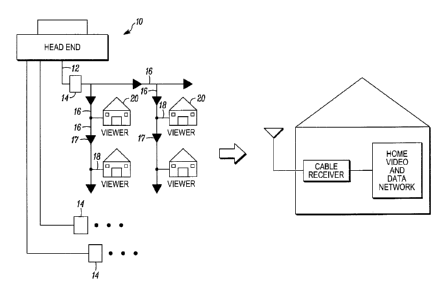
[0003] Referring to FIG 1, cable TV (CATV) systems were initially deployed
as video delivery systems. In its most basic form the system received video
signals at
the cable head end, processed these for transmission and broadcast them to
homes via
a tree and branch coaxial cable network. In order to deliver multiple TV
channels
concurrently, early CATV systems assigned 6MHz blocks of frequency to each
channel and Frequency Division Multiplexed (FDM) the channels onto the coaxial
cable RF signals. Amplifiers were inserted along the path as required to boost
the
signal and splitters and taps were deployed to enable the signals to reach the
individual homes. Thus all homes received the same broadcast signals.
[0004] As the reach of the systems increased, the signal distortion and
operational cost associated with long chains of amplifiers became problematic
and
segments of the coaxial cable were replaced with fiber optic cables to create
a Hybrid
Fiber Coax (HFC) network to deliver the RF broadcast content to the coaxial
neighborhood transmission network. Optical nodes in the network acted as
optical to
electrical converters to provide the fiber-to-coax interfaces.
[0005] As the cable network evolved, broadcast digital video signals were
added to the multiplexed channels. The existing 6MHz spacing for channels was
retained but with the evolving technology, each 6MHz block could now contain
multiple programs. Up to this point, each home received the same set of
signals
broadcast from the head end so that the amount of spectrum required was purely
a
function of the total channel count in the program line-up.
[0006] The next major phase in CATV evolution was the addition of high
speed data service, which is an IP packet-based service, but appears on the
HFC
network as another 6MHz channel block (or given data service growth, more
likely as
-1-
ARRIS Docket ARRH001 6
multiple 6MHz blocks). These blocks use FDM to share the spectrum along with
video services. Unlike broadcast video, each IP stream is unique. Thus the
amount of
spectrum required for data services is a function of the number of data users
and the
amount of content they are downloading. With the rise of the Internet video,
this
spectrum is growing at 50% compound annual growth rate and putting significant
pressure on the available bandwidth. Unlike broadcast video, data services
require a
two-way connection. Thus, the cable plant had to provide a functional return
path.
Pressure on the available bandwidth has been further increased with the advent
of
narrowcast video services such as video-on-demand (VOD), which changes the
broadcast video model as users can select an individual program to watch and
use
VCR-like controls to start, stop, and fast-forward. In this case, as with data
service,
each user requires an individual program stream.
[0007] Thus, the HFC network is currently delivering a mix of broadcast
video, narrowcast video, and high speed data services. Additional bandwidth is
needed both for new high definition broadcast channels and for the narrowcast
video
and data services. The original HFC network has been successfully updated to
deliver
new services, but the pressure of HD and narrowcast requires further change.
The
HFC network is naturally split into the serving areas served from the
individual fiber
nodes. The broadcast content needs to be delivered to all fiber nodes, but the
narrowcast services need only be delivered to the fiber node serving the
specific user.
Thus, there is a need to deliver different service sets to each fiber node and
also to
reduce the number of subscribers served from each node (i.e. to subdivide
existing
serving areas and thus increase the amount of narrowcast bandwidth available
per
user).
[0008] FIG I is a generalized representation of part of the cable TV
infrastructure, which includes the cable head end; the Hybrid Fiber Coax (HFC)
transmission network, and the home. The CATV head end receives incoming data
and video signals from various sources (e.g., fiber optic links, CDN's, DBS
satellites,
local stations, etc.). The video signals are processed (reformatting,
encryption,
advertising insertion etc.) and packaged to create the program line up for
local
distribution. This set of video programs is combined with data services and
other
-2-
ARRIS Docket ARRH0016
system management signals and prepared for transmission over the HFC to the
home.
All information (video, data, and management) is delivered from the head end
over
the HFC network to the home as RF signals. In the current practice, systems in
the
head end process the signals, modulate them to create independent RF signals,
combine these into a single broadband multiplex, and transmit this multiplex
to the
home. The signals (different video channels and one or more data and
management
channels) are transmitted concurrently over the plant at different FDM
frequencies.
In the home, a cable receiver decodes the incoming signal and routes it to TV
sets or
computers as required.
[0009] Cable receivers, including those integrated into set-top boxes and
other
such devices, typically receive this information from the head end via coaxial
transmission cables. The RF signal that is delivered can simultaneously
provide a
wide variety of content, e.g. high speed data service and up to several
hundred
television channels, together with ancillary data such as programming guide
information, ticker feeds, score guides, etc. Through the cable receiver's
output
connection to the home network, the content is delivered to television sets,
computers,
and other devices. The head end will typically deliver CATV content to many
thousands of individual households, each equipped with a compatible receiver.
[0010] Cable receivers are broadly available in many different hardware
configurations. For example, an external cable receiver is often configured as
a small
box having one port connectable to a wall outlet delivering an RF signal, and
one or
more other ports connectable to appliances such as computers, televisions, and
wireless routers or other network connections (e.g., 10/100/1,000 Mbps
Ethernet).
Other cable receivers are configured as circuit cards that may be inserted
internally in
a computer to similarly receive the signals from an RF wall outlet and deliver
those
signals to a computer, a television, or a network, etc. Still other cable
receivers may
be integrated into set-top boxes, such as the Motorola DCX3400 HD/DVR, M-Card
Set-Top, which receives an input signal via an RF cable, decodes the RF signal
to
separate it into distinct channels or frequency bands providing individual
content, and
provides such content to a television or other audio or audiovisual device in
a manner
that permits users to each select among available content using the set top
box.
-3-
ARRIS Docket ARRH0016
[0011] As previously mentioned, the CATV transmission architecture has
been modified to permit data to flow in both directions, i.e. data may flow
not only
from the head end to the viewer, but also from the viewer to the head end. To
achieve
this functionality, cable operators dedicate one spectrum of frequencies to
deliver
forward path signals from the head end to the viewer, and another (typically
much
smaller) spectrum of frequencies to deliver return path signals from the
viewer to the
head end. The components in the cable network have been modified so that they
are
capable of separating the forward path signals from the return path signals,
and
separately amplifying the signals from each respective direction in their
associated
frequency range.
[0012] The Hybrid/Fiber Coax (HFC) cable network architecture broadly
depicted in FIG. 1 includes a head end system 10 having multiple devices for
delivery
of video and data services including EdgeQAMS (EQAMs) for video, cable modem
termination systems (CMTS) for data, and other processing devices for control
and
management. These systems are connected to multiple fiber optic cables 12 that
go to
various neighborhood locations that each serve a smaller community. A fiber
optic
neighborhood or multi-neighborhood node 14 is located between each fiber optic
cable 12 and a corresponding trunk cable 16, which in turn is interconnected
to the
homes 20 through drop cables 18 and feeder cables (not shown). Because the
trunk
cable 16, as well as the branch networks and feeder cables 18, each propagate
RF
signals using coaxial cable, the nodes 14 convert the optical signals to
electrical
signals that can be transmitted through a coaxial medium, i.e. copper wire.
Similarly,
when electrical signals from the home reach the node 14 over the coaxial
medium,
those signals are converted to optical signals and transmitted across the
fiber optic
cables 12 back to the systems at the head end 10. The trunk cables 16 and/or
feeder
cables 18 may include amplifiers 17. Connected to each trunk cable 16 is a
branch
network that connects to feeder cables (or taps) that each enter individual
homes to
connect to a respective cable receiver.
[0013] Hybrid fiber/coax networks generally have a bandwidth of
approximately 750 MHz or more. Each television channel or other distinct
content
item transmitted along the forward path from the head end to a user may be
assigned a
-4-
ARRIS Docket ARRH001 6
separate frequency band, which as noted earlier has a typical spectral width
of 6 MHz.
Similarly, distinct content delivered along the return path from a user to the
head end
may similarly be assigned a separate frequency band, such as one having a
spectral
width of 6.4 MHz. In North America, the hybrid fiber/coax networks assign the
frequency spectrum between 5 MHz and 42 MHz to propagate signals along the
return path, and assign the frequency spectrum between 50 MHz and 750 MHz or
more to propagate signals along the forward path.
[0014] Referring to FIG. 2, a cable modem termination system (CMTS) 30
may be installed at the head end, which instructs each of the cable modems
when to
transmit return path signals, such as Internet protocol (IP) based signals,
and which
frequency bands to use for return path transmissions. The CMTS 30 demodulates
the
return path signals, translates them back into (IP) packets, and redirects
them to a
central switch 32. The central switch 32 redirects the IP packets to an IP
router 34 for
transmission across the Internet 36, and to the CMTS which modulates forward
path
signals for transmission across the hybrid fiber coax cables to the user's
cable modem.
The central switch 32 also sends information to, and receives information
from,
information servers 38 such as video servers. The central switch 32 also sends
information to, and receives information from, a telephone switch 40 which is
interconnected to the telephone network 42. In general, cable modems are
designed
to only receive from, and send signals to, the CMTS 30, and may not
communicate
directly with other cable modems networked through the head end.
[0015] FIG. 3 shows an exemplary architecture for delivering CATV content
between a head end 10 to a node 14. The head end 10 may in some instances
include a
plurality of direct modulation EdgeQAM units 50 which each receive digitally
encoded video signals, audio signals, and/or IP signals, and each directly
outputs a
spectrum of amplitude-modulated analog signal at a defined frequency or set of
frequencies to an RE' combining network 52, which in turn combines the
received
signals. An optical transmitter 54 then sends the entire spectrum of the
multiplexed
signals as an analog transmission through an optical fiber network 56 along a
forward
path to the node 14. The fiber optic network, as will be explained in more
detail later,
is also capable of conveying optical signals from the node 14 to the head end
10 via
-5-
ARRIS Docket ARRH0016
an optical path between a transmitter 58 in the node 14 and a receiver 60 in
the head
end . In the specification, the drawings, and the claims, the terms "forward
path" and
"downstream" may be interchangeably used to refer to a path from a head end to
a
node, a node to an end-user, or a head end to an end user. Conversely, the
terms
"return path", "reverse path" and "upstream" may be interchangeably used to
refer to
a path from an end user to a node, a node to a head end, or an end user to a
head end.
Also, it should be understood that, unless stated otherwise, the term "head
end" will
also encompass a "hub," which is a smaller signal generation unit downstream
from a
head end, often used for community access channel insertion and other
purposes, that
generally mimics the functionality of a head end, but may typically not
include
equipment such as satellite dishes and telephone units. Hubs are commonly
known to
those skilled in the art of the present disclosure. It should be understood
that although
FIG. 3 illustrates a head end 10 that utilizes direct modulation EdgeQAMs,
other
architectures may employ other modulators, such as an analog EdgeQAM modulator
or a Converged Cable Access Platform (CCAP) modulation system.
[0016] Directly-modulated EdgeQAM units have become increasingly
sophisticated, offering successively higher densities, which in turn means
that each
EdgeQAM unit can process more channels of CATV data. For example, modern
EdgeQAM modulation products can now simultaneously generate 32 or more
channels on a single output port. With more channels being modulated per
output
port, the amount of combining required by the RF combining network 52 is
reduced,
with a corresponding simplification in the circuitry at the head end. The term
`QAM'
is often used to interchangeably represent either: (1) a single channel
typically 6MHz
wide that is Quadrature Amplitude Modulated (thus a "32 QAM system" is
shorthand
for a system with 32 Quadrature Amplitude Modulated channels; or (2) the depth
of
modulation used by the Quadrature Amplitude Modulation on a particular
channel,
e.g. 256 QAM means the signal is modulated to carry 8 bits per symbol while
4096
QAM means the signal is modulated to carry 12 bits per symbol. .A higher QAM
channel count or a higher QAM modulation means that a higher number of content
"channels" can be delivered over a transmission network at a given standard of
quality for audio, video, data, etc. QAM channels are constructed to be 6 MHz
in
-6-
ARRIS Docket ARRH001 6
bandwidth in North America, to be compatible with legacy analog TV channels
and
other existing CATV signals. However, more than one video program or cable
modem system data stream may be digitally encoded within a single QAM channel.
The term channel is unfortunately often used interchangeably, even though a
QAM
channel and a video program are not often the same entity ¨ multiple video
programs
can be and usually are encoded within a single 6 MHz QAM channel. In this
case, the
modern EdgeQAM modulation products generate multiple instances of the 6 MHz
bandwidth QAM channels. This simplifies the head end structure since some
subset
of the RF combining is now performed within the EdgeQAM units rather than in
the
external RF combining network. Packaging multiple QAM generators within a
single
package also offers some economic value.
[0017] As noted previously, modern CATV delivery systems over an HFC
network provides content that requires communication along both a forward path
and
a return path, and over time, the quantity and quality of data transmission
along each
of these paths has increased drastically, which can be seen for example in the
evolution of the DOCSIS standard from its original 1.0 release to the
impending 3.1
release.
[0018] DOCSIS (Data Over Cable Service Interface Specifications) was
developed by a consortium of companies, including Cable Labs, ARRIS, Cisco,
Motorola, Netgear, and Texas Instruments, among others. The first
specification,
version 1.x, was initially released in March 1997 and called for a downstream
throughput of approximately 43Mbps and an upstream throughput of approximately
10Mbps along a minimum of one channel. DOCSIS 2.0, released in late 2001
increased the maximum upstream throughput to approximately 31Mbps, again for a
minimum of one channel. DOCSIS 3.0, released in 2006 required that hardware be
able to support the DOCSIS 2.0 throughput standards of 43Mbps and 31Mbps,
respectively, along minimum of four channels in each direction. The DOCSIS 3.1
platform is aiming to support capacities of at least 10Gbps downstream and
1Gbps
upstream using 4096 QAM. The new specification aims to replace the 6 MHz
downstream and 6.4 MHz upstream wide channel spacing with smaller 25 kHz to 50
kHz orthogonal frequency division multiplexing (OFDM) subcarriers, which can
be
-7-
ARR1S Docket ARM-10016
bonded inside a block spectrum that could end up being about 192 MHz wide for
downstream and 96 MHz for upstream.
[0019] Providing increasing throughput along the upstream path has been
particularly problematical the presence of upstream impairments including
ingress.
Ingress is radio frequency (RF) energy that has varying bandwidth and RF
levels and
can enter the CATV upstream plant via cable network defects. CATV network
defects
may include loose or corroded connectors, untenninated ports, and damaged
cables,
for example. Thus, to continue to meet the evolving needs of delivering CATV
content, improved techniques for transmission along the upstream path, and
particularly in the presence of upstream impairments. are desirable.
BRIEF DESCRIPTION OF THE SEVERAL VIEWS OF THE DRAWINGS
[0020] FIG. 1 shows an exemplary Hybrid/Fiber Coax CATV network
including a head end that delivers CATV content to a plurality of homes.
[0021] FIG. 2 shows an exemplary architecture of a head end, such as the
ones
shown in FIG. 1 .
[0022] FIG. 3 shows an exemplary EdgeQAM architecture for a head end to
communicate with a node along a forward path to deliver CATV content over a
network.
[0023] FIG. 4 shows an example of an upstream transmission system
according to one aspect of the present disclosure.
[0024] FIG. 5 shows a band-limited signal capable of being sampled at a
rate
of less than twice its upper cutoff frequency while still preserving all its
information.
[0025] FIG. 6shows a brassboard DRR output spectrum using existing 2x85
Digital Return Transmitter (DRT) and Digital Return Receiver (DRR) systems.
[0026] FIG. 7 shows an exemplary architecture including the system shown
in FIG. I.
[0027] FIG. 8 and 9 each show respective examples of DOCSIS 3.0 capacity
aggregation in a node.
-8-
ARRIS Docket ARRH0016
Detailed Description
[0028] FIG. 4 generally illustrates an improved system for transmitting
data
along a return path from a Digital Return Transmitter (DRT) 107, in a node for
example, to a Digital Return Receiver (DRR) 109 in a head end, for example.
Specifically, Fig. 4 shows a DRT 107 receiving two signals 102 and 104 for
transmission to the DRR 109. Future DOCSIS channels may occupy a maximum
bandwidth of 96 MHz, approximately 15 times larger than the largest upstream
DOCSIS 3.0 channel, where each of the signals 102 and 104 can generate a
digital
signal rate anywhere in the range of 800 Mbps to 2.25 Gbps depending on the
signal
band, sampling rate and the number of bits used to sample each signal. Even
when
digitizing only two of these signals, and transmitting them both together
using time
division multiplexing of the digital signals, the aggregated digital signal
rate may
exceed the capabilities of existing digital and optical transport platforms.
[0029] The system of FIG. 4, however, permits the signals 102 and 104 to be
simultaneously transmitted using existing architectures by taking advantage of
the
principles of bandpass sampling. Ordinarily, the Nyquist sampling theorem
dictates
that in order to completely preserve the information in a transmitted signal
occupying
a limited portion of the frequency spectrum, the signal must be sampled at a
rate equal
to twice the upper frequency limit of the signal. For example, if the maximum
frequency of the signal is 100 MHz, the signal must be sampled at 200 million
samples per second in order to preserve all the information in the signal. At
even
modest symbol bit rates of say six to eight bits per sample, the required
throughput to
sample at the full Nyquist rate can become significant.
[0030] FIG. 5, however, illustrates a circumstance in which all information
in
a transmitted signal may be preserves without sampling at the rate of twice
the upper
cutoff frequency of the signal. Specifically, a signal 140a, 140b may be
bandlimited to
a 20MHz segment of the frequency spectrum from plus or minus 90MHz to plus or
minus 110MHz. It will be understood by those skilled in the art that the
signal need
only be sampled on the positive sideband, as the negative sideband is simply a
mirror
-9-
ARRIS Docket ARRH001 6
image of the positive sideband. FIG. 5 also shows spectral aliases 142 of the
signal
140a that extend from the baseband to the signal component 140a. Stated
differently,
a theoretical repeating signal occupying a single frequency on the spectrum at
100
MHz, thus repeating 100 million times per second, has a spectral alias
occurring at
every 1Hz interval. By extension, the signal 140a has spectral aliases 142
that begin at
baseband and repeat at every integral multiple of the width of the signal
140a. If
signal 140a is located on the spectrum at an integral multiple of its width,
the spectral
aliases do not overlap, and thus the signal 140a may be fully sampled by
sampling its
baseband spectral alias only, i.e. by sampling at a rate of twice the spectral
width
signal 140a rather than twice its upper cutoff frequency. If the signal 140a
is located
on the spectrum at a position that is not an integral multiple of its width,
the spectral
aliases will overlap, but the signal 140a may be fully sampled by sampling at
a rate
that is greater than twice its spectral width, but still much less than twice
its upper
cutoff frequency.
[0031] As noted previously, existing hybrid fiber coax architectures
include
components that would ordinarily be considered as lacking the capability of
processing two or more signals 102 and 104 sequentially positioned on the
frequency
position, if those signals conformed to anticipated future DOCSIS standards.
The
present inventors realized, however, that by taking advantage of bandpass
sampling
principles, existing architectures could be modified without the need to
upgrade much
of the equipment in existing architectures.
[0032] Referring again to FIG. 4, the disclosed system may preferably
sample
and transmit plural wideband orthogonal frequency division multiple access
(OFDM)
channels 102 and 104, each with up to 96MHz BW. It should be understood,
however, that other embodiments may simultaneously transmit more than two OFDM
channels, such as four channels for example. guardband 106 between channels
may be
included to prevent interference between the channels. In this example, a
fully loaded
DOCSIS return may require an upper frequency of >200MH, e.g. a lower OFDM
channel 102 from 10-106MHz and a upper OFDM channel 104 from 126-222MHz.
To digitize the continuous band from 0 to 222MHz, the sampling rate would need
to
-10-
ARRIS Docket ARRH0016
be >444Msps (likely ¨510Msps), well in excess of devices used in current 2x85
digital return.
[0033] A DRT 107 may first filter the signals 102 and 104 with a diplex
filter
108 that separates the signals 102, 104 into a first transmission path 109 for
the signal
104 and a second transmission path 111 for the signal 102. The diplex filter
preferably
splits the signals 102 and 104 at a split frequency of approximately 116 MHz.
The
term "approximately in this context means anywhere within a range of 106 MHz
to
126 MHz, on the assumption that each of the signals 102 and 104 are about 96
MHz
in width and the guardband is about 20 MHz in width. Alternative embodiments
may
use a split frequency outside of this range, however, depending on the width
of the
signals 102 and 104. The signal 102 is preferably filtered by a low pass
filter 110
while the signal 104 is preferably filtered by a bandpass filter 112.
Preferably, each
signal 102 and 104 may be amplified after being respectively filtered. The
bandpass
filter 112 is preferably configured to pass a range of frequencies that
closely matches
the frequency bounds of the signal 104, and to filter out all other
frequencies. After
each signal 102, 104 is filtered by a respective one of the filters 110 and
112, the
signals 102 and 104 are converted to a digital signal by a dual A/D converter
114. The
dual A/D converter 114 can be operated with independent analog inputs and/or
can be
used for diversity reception of signals, operating identically on the same
carrier but
from separate antennae. The output from the dual A/D converter 114 is input to
a
multiplexer 116, a device that selects one of several analog or digital input
signals and
forwards the selected input into a single line.
[0034] As can be seen in FIG. 4, between signal 102 and signal 104 is a
guardband 106, which accounts for the fact that the diplex filter 108 has a
significant
cross-over region, in which frequencies above the lowpass portion of the
diplex filter
get passed, and frequencies below the highpass portion of the diplex filter
get passed.
The guardband, though necessary to protect the integrity of the respective
signals 102
and 104, contains no data, hence the present inventors recognized that there
is no
reason for sampling frequencies within the guardband. Thus, the dual A/D
converter
is preferably configured to only sample the respective bands occupied by the
signals
102 and 104, and without sampling the frequencies that occupy the guardband.
-11-
ARRIS Docket ARRH001 6
[0035] As can easily be recognized, by using bandpass filter 112 in
conjunction with the disclosed dual AID converter 114, a signal with bandwidth
of
96MHz can be sampled at >192Msps (likely ¨232Msps), close to the current 2x85
sampling rate of 202Msps. Thus, the use of bandpass sampling transforms the
2x85
Digital Return into a 1x200+ Digital Return. The use of digitized blocks to
leverage
the DSP concept of bandpass sampling may achieve strict Nyquist compliance,
aggregating the signals on the receive end.
[0036] In some embodiments, a single hardware design can support both
2x85MHz and 1x200+MHz. Thus, one hardware design can support both 2x85MHz
and 1x200+MHz, avoiding a total re-design of the 2x85MHz legacy designs, which
would be more complex and costly. In the DOCSIS digital return implementation
shown in FIG. 4, an increase in current digital processing rates, e.g., from
202 to 232
Msps, supports the two (2) 96MHz bandwidth channels 102 and 104. For example,
one of the current time-division multiplexing (TDM) channels may carry the
lower
96MHz DOCSIS 3.1 channel 102 via conventional lowpass sampling, such as via
low
pass filter 110. The second of the TDM channels may carry the upper 96MHz
DOCSIS 3.1 channel 104 via bandpass sampling using bandpass filter 112.
[0037] As shown in FIG. 4, by bandpass sampling the advanced signaling on a
DOCSIS channel, ingress impairments may be filtered out from the optical
transmission path, since the filter characteristics are closely matched to the
advanced
signaling channel, e.g. the 96 MHz orthogonal frequency division multiple
access
(OFDMA signal) proposed by the DOCSIS 3.1 standard.
[0038] Preferably, the bandpass filter characteristics closely match the
advanced signaling channel (or channels), thereby filtering out ingress
impairments
from the optical transmission path. Thus, the disclosed techniques may address
modern cable upstream issues in a more economical manner than existing
architectures. For example, in a Data Over Cable Service Interface
Specifications
(DOCSIS) implementation, the disclosed techniques may enable DOCSIS over
extended splits by using the relationship between the state of the art in
upstream
digital return products (2xTDM @ 85 MHz split) and newly defined upstream
approaches, e.g., using 2x96 MHz bands of OFDMA.
-12-
ARRIS Docket ARRH0016
[0039] It should be understood that other center frequencies, bandwidths,
and
aggregation schemes can be chosen to provide desired performance. For example,
if a
signal band is not completely full, all the dynamic range (sampling rate) can
be given
to the occupied bandwidth to achieve a better SNR ratio. Similar techniques
can be
used to protect dynamic range and/or avoid overdrive due to regions of
significant
interference and ingress that are unoccupied with desired signals, such as the
low end
of the upstream band, or perhaps the FM band when upstream signal capacity is
extended even further beyond DOCSIS 3.1.
[0040] Also, the disclosed techniques apply to any future extension of
upstream bandwidth capacity - the tradeoff between full band digitization,
processing,
and transport versus aggregated spectrum increments. While the summation of
summing spectrum segments to a total bandwidth is linear, the implementation
costs
of summing spectrum components that match a full single bandwidth approach may
not be linear.
[0041] The multiplexer 116 may combine several input signals into one
output
signal, which carries several communication channels. The multiplexer 116 may
increase the amount of data that can be sent over the channel within a certain
amount
of time and bandwidth. The multiplexer 116 makes it possible for the bandpass
filter
and low pass filter to share the Dual A/D 114. The MUX and Framing FPGA 116
may provide the output to a serializer and Electrical-to-Optical (E20)
converter 118.
[0042] A Digital Return Receiver (DRR) 109 may included an Optical-to-
Electrical (02E) converter and deserializer component 120 that provides an
output to
a deframe and demultiplexer FPGA 122. The demultiplexer 122 may take a single
input signal and select one of many data output-lines connected to a single
input. The
demultiplexer 122 may take a single input signal that carries many channels
and
separate those over multiple output signals for delivery to a Dual A/D
converter 124,
where a demultiplexed first output signal 125 can be delivered to a bandpass
filter 126
and a second output signal 127 is provided to a low pass filter 128. The
signals 125
and 127 may be combined by a diplex filter/combiner 130 to re-create the
original
signals 102 and 104.
-13-
ARRIS Docket ARRH0016
[0043] The center frequencies and bandwidths described herein are non-
limiting examples of trading between full band digitization, processing and
transport
vs. the disclosed aggregated spectrum increments. For example, other center
frequencies and bandwidths and aggregation schemes can be chosen to achieve
this
result to provide other performance advantages. In particular, for example, if
the band
is not completely full, all of the dynamic range can be given to the occupied
BW to
optimize performance (better SNR). This same mechanism also can be used to
protect the dynamic range and/or avoid overdrive due to regions of significant
interference and ingress that are unoccupied with desired signals, such as the
low end
of the upstream band or perhaps the FM band when the upstream is extended such
as
is anticipated by this disclosure.
[0044] Further, the disclosed concepts of separately digitizing single
channels
applies to future upstream bandwidth and recognizes the tradeoff between full
band
digitization, processing, and transport vs. aggregated spectrum increments.
While the
algebra of summing spectrum segments to a total BW required is linear, the
implementation costs of summing spectrum components that match a full single-
BW
approach may not be linear, in particular when processing is pushing the
technology
envelope, which has been inherently the situation recently in the competitive
environment of broadband evolution. Existing solutions do not make use of
bandpass
sampling in the area of digital return; in particular, the disclosed
techniques for using
bandpass sampling, a digital signal processing technique, to enable flexible
selection
of critical system parameters including bandwidth, and center frequency
location,
have not been contemplated. Dynamic selection of these critical system
parameters
enables both efficient transmission of CATV upstream paying services and
avoidance
of upstream impairments including ingress and laser clipping.
[0045] FIG. 6 depicts a brassboard DRR output spectrum using existing 2x85
DRT and DRR boards. In this example, 85MHz analog lowpass filters in DRT and
DRR are bypassed in one of the TDM channels. Analog amps currently used have
decreasing gain from 85 to 200MHz and therefore the passband slope and ripple
may
be further optimized. Sampling and processing rate has not been bumped, in
this
example, still running at a rate of 202Msps. Due to keeping rate at 202Msps,
in this
-14-
ARRIS Docket ARRH0016
embodiment, two ¨80MHz BW channels are used rather than two (2) 96MHz
channels. In this embodiment, the lower channel is 5-85MHz and the upper
channel
is 113-197MHz. An 80MHz noise block to simulate lower wideband channel and
fourteen 256QAMs is used to simulate upper wideband channel. Signals are being
passed with respectable SNR and distortions but MER at higher frequencies is
being
limited by phase jitter.
[0046] In embodiments, phase jitter and phase noise requirements are
determined for the clocks to support 42+dB MER at the upper end of the band,
which
may dictate hardware design choices to meet the phase jitter requirements.
Further,
analog amps and filters may be designed to support upper wideband channel and
optimize passband response. In embodiments where the sampling rates are bumped
from 202 to 232 MHz, the phase jitter and phase noise requirements may be
determined. The DRT and DRR boards may be configured to deliver >42dB MER at
high end of band.
[0047] FIG. 7 depicts an exemplary architecture 150 by which data may be
transmitted along a return path between a plurality of end user cable modems
152 and
a CMTS 156 in a head end 157, through a node 154. In this architecture, a DRT
158
in the node receives respective signals from each of the modems 152 via an
array of
coaxial cables 160. The coaxial cables may be connected to modems 152 using
two-
way splitters used as combiners 162 such that a respective two-way splitter
162
propagates signals onto a coaxial cable 160 from a pair of modems 152. The
transmitter 158 is preferably configured as shown in FIG. 4, and propagates a
digital
signal onto a fiber optic transmission line 164 at two wavelengths, and which
is
carried to a receiver 166 that is also preferably configured as shown in FIG.
4. After
converting the incoming digital signals to respective analog RF signals, the
receiver
166 may convey them to the CMTS 156 using coaxial cables 168 and two-way
splitters 170.
[0048] It should be understood that, although FIG. 4 only shows an
architecture for providing data along an upstream path from the cable modems
152 to
the CMTS 156, such an architecture also includes equipment to provide data
along the
forward path from the CMTS 156 to the node 145 and on to the cable modems 152.
-15-
ARRIS Docket ARRH0016
[0049] FIG. 8 shows estimates in a system similar to that of FIG. 6, but
without using the bandpass filter 112 of FIG. 4. In this example, data is
delivered
along an upstream path to the node by a coaxial cable carrying 85MHz blocks of
data.
In this example, the throughput or capacity at the node was estimated to range
from
approximately 307 Mbps to 983 Mbps depending on the number of channels and/or
the depth of modulation, e.g. 64 QAM versus 256 QAM.
[0050] FIG. 9 shows estimates in a system similar to that of FIG. 6, but
instead using the bandpass filter 112 of FIG. 4, under several channel
conditions
presumed to be consistent with the upcoming DOCSIS 3.1 standard, e.g. up to
1024
QAM while still using 85 MHz blocks. In this example, the throughput or
capacity at
the node was measured to range from approximately 491 Mbps to 1,536 Mbps
depending on the number of channels and/or the depth of modulation, e.g. 256
QAM
versus 1024 QAM. As can be seen from a comparison between FIGS 8 and 9, the
use of a bandpass filter and bandpass sampling as disclosed in the present
application
approximately doubles the upstream throughput in a CATV transmission system
using
lower complexity hardware.
[0051] In some embodiments, the disclosed techniques may be implemented
via an incremental complexity addition to a current digital return product,
e.g., an >
85 MHz digital return product. Incremental complexity addition to existing
products
may enable upgrades, e.g., > 85 MHz CATV upstream upgrades, at an incremental
cost to cable system operators, thereby avoiding the use of more expensive
analog-to-
digital converters (ADCs) associated with sampling equivalent frequency
ranges. In
an example digital return device, real estate in the node housing of an SG4
optical hub
would enable cable operators to easily aggregate capacities as high as 6 GB
per node
as needed.
[0052] The disclosed techniques provide flexibility to support dynamic
center
frequency locations. The ability to support dynamic center frequency locations
may
allow cable operators the flexibility to focus optical link transmission on
paying
services, rather than the traditional approach of transmitting both paying
services plus
ingress.
-16-
ARRIS Docket ARRH0016
[0053] The terms and expressions that have been employed in the foregoing
specification are used therein as terms of description and not of limitation,
and there is
no intention, in the use of such terms and expressions, of excluding
equivalents of the
features shown and described or portions thereof, it being recognized that the
scope of
the claimed subject matter is defined and limited only by the claims that
follow.
-17-