Note: Descriptions are shown in the official language in which they were submitted.
CA 02858448 2014-06-06
WO 2013/083721
PCT/EP2012/074694
-1-
Multi-phase metering of fluid flows
FIELD OF THE INVENTION
The present invention addresses the current difficulties in three-phase
metering of
fluid flows. The need for this commonly arises at (for example) wellheads,
where it is
necessary to measure the individual flow rates of oil, water and gas fractions
within the fluid
flow out of an oil well.
BACKGROUND ART
Knowledge of the individual flow rates of the gas fraction, the oil fraction,
and the
water fraction within the flow of fluid from an oil well is an important part
of the efficient
management of the well and the associated subsurface reservoir. Such wells
typically tap
into reservoirs such as that shown in figure 1, in which a simplified well is
shown
penetrating a reservoir. The reservoir consists of a permeable rock formation
typically filled
with a lower layer of water 110, an intermediate layer of oil 112, and an
upper layer of gas
114 trapped under a layer of cap rock 116. The result of this is that the
balance between
the fractions of each that are extracted is affected by the positioning of the
well perforations
120 at the lower end of the production string 122 relative to the layers, and
the flow rate of
the fluid out of the well. The flow rate is relevant in that over production
of a well can
reduce the total amount of oil recovered due to a number of reasons, including
drawing the
underlying water layer 124 up towards the perforations 120 and creating a cone
of water
above the undisturbed oil/water contact in the region of the well. The
appropriate response
to this is to reduce the overall flow rate in order to optimise the oil
extraction rate. Typically
this is achieved with a choke valve 134 located in or close to the wellhead
132. The choke
value may be variable, but more commonly it consists of a fixed orifice of a
precise flow
section that under normal operating conditions, produces "critical flow", a
supersonic flow
that is only dependant on the wellhead pressure upstream of the choke,
independent of the
pressure downstream of the choke. Selecting a specific size of choke enables
the reservoir
engineer to select an optimum flowrate for the well. Within a reasonably wide
range, the
well flowrate is then not affected by varying back pressure in the flowline
130 to the surface
facility 126.
CA 02858448 2014-06-06
WO 2013/083721
PCT/EP2012/074694
-2-
The surface facility separates the oil, water and gas streams and measures the
flowrate of each phase, disposes of the water (and sometimes gas), and passes
the other
fluids to market. The surface facility typically receives the flow from many
wells, and has a
test separator and a production separator. Most of the wells are comingled and
flow into
the production separator, where only the aggregate flowrates are available.
From time to
time, the flow from each well is sent to the test separator, and then the
phase flowrates for
oil, gas and water for that well are measured. It will be clear that for most
of the time, the
well flows are not measured; instead flows are inferred from general
measurements by a
process known in the industry as "allocation". Allocation is important as the
reservoir and
well production can only be optimised if the flow from each well is known.
Also, in certain
countries, royalty rates for each state are calculated on the basis of well
production within
the state boundaries, so a general production figure for an entire oil field
that crosses state
boundaries is not detailed enough, and individual well production figures are
needed.
Individual separators for each well would be very costly, and so there is a
need for a
multiphase flowmeter (MPFM) that is cost effective for individual wells. A
further advantage
of installing MPFMs on each well is that rather than having individual
flowlines running back
to the surface facility, it is possible to comingle the flows of wells into a
single larger flowline
back to the facility. This approach has considerable cost advantages,
particularly for subsea
wells.
Attention has therefore been directed to in-line flowmeters able to
distinguish
between the three fractions. An example can be seen in US 5,461,930 which
discusses the
measurement of two- and three-phase fluid flow. Volumetric and momentum (mass)
flow
meters are provided, which yield corresponding data from which (and from
knowledge of
the respective densities), the relative flow rates of the different phases can
be determined.
Another example can be seen in US2004/0182172A1, which uses venturis and
chokes in the flowline to create pressure differentials along the flowline.
The gas fraction is
very much more compressible than the oil and water fractions, and therefore
from assessing
the pressure differentials produced by several different chokes and/or
venturis, it is possible
(in principle) to determine the gas fraction. The relative water & oil
fractions can then be
determined by electrical properties of the fluid, particularly its capacitive
properties in a
CA 02858448 2014-06-06
WO 2013/083721
PCT/EP2012/074694
-3-
manner that is acknowledged by US2004/0182172A1 as being known in the oil &
gas
industries.
This arrangement is proposed as an in-line meter 128 (fig 1) for use in the
flowline
130 at some intermediate point between the production well and a remote
processing
location. However, as discussed in US 5,461,930 in relation to still earlier
designs, it suffers
from the inherent difficulty that in order to create significant pressure
differentials, there
must be a significant flow restriction (by way of either a choke or a
venturi). Thus, the flow
of the fluid out of the well and to the remote processing location may be
adversely affected.
If the meter is designed so that there is little effect on flow, then the
pressure differentials
are correspondingly reduced and the accuracy of the meter is affected.
Typically, such a
device will have to measure pressure differentials of 1 or 2 bar in a base
pressure of about
100 bar. To determine the proportions of the different fractions, three
pressure differentials
need to be compared, meaning that in order to obtain accurate information as
to the
fractional ratios, the pressure differentials will need to be accurate to
millibar levels. This is
a significant challenge.
SUMMARY OF THE INVENTION
The present invention aims to provide a multi-phase flow meter that can
operate
accurately without having an adverse effect on the fluid flow out of the well
(or other
context in which it is installed) and along the flowline.
It therefore provides a multi-phase flow meter, including a flow conduit
leading from
an inlet to an outlet and comprising a variable inlet restriction, a variable
outlet restriction, a
pressure sensor and a volumetric flow meter, located between the variable
inlet restriction
and the variable outlet restriction, the flow meter further comprising a
controller adapted to
receive data from the pressure sensor and the volumetric flow meter, and to
adjust the
variable inlet restriction and the variable outlet restriction in accordance
with at least one
program, wherein the at least one program causes the controller to adjust one
of the
variable inlet restriction and the variable outlet restriction such that the
fluid pressure
between them adopts a first pressure, then further adjust the restriction such
that the fluid
pressure between the restrictions adopts a second and different pressure, and
to record the
first pressure, the second pressure, and the volumetric fluid flow rates at
the first pressure
and at the second pressure, whilst adjusting the other of the variable inlet
restriction and
CA 02858448 2014-06-06
WO 2013/083721
PCT/EP2012/074694
-4-
the variable outlet restriction so that the total flow restriction imposed by
the two
restrictions is maintained at a substantially constant level.
The variable inlet and outlet restrictions can be continuously variable
between a
minimum restriction and a maximum restriction, ideally monotonically so.
Ideally, when at
the maximum restriction, all flow is prevented. This allows maximum
flexibility of the
device. Alternatively, variable inlet or outlet restriction could be variable
between a plurality
of discrete values, which may provide the necessary degree of freedom at lower
cost or
complexity. Such an arrangement could be, for example, an on-off valve in
parallel with a
bypass path containing a flow restriction.
The volumetric flow meter can be an ultrasonic flow meter or a turbine flow
meter,
for example.
We prefer that the controller has a further program, in addition to the
program
mentioned above, which causes the controller to close fully the inlet or the
outlet flow
restriction and to open fully the outlet or the inlet flow restriction,
respectively, to maintain
this state for a period of time, and to adjust the calibration of at least one
of the pressure
sensor and the volumetric flow meter during this period.
Thus, a multi-phase flow meter according to the invention can be summarised as
being one that includes a flow conduit in which is located a variable inlet
restriction, a
variable outlet restriction, and a control arrangement adapted to vary the
restrictions in
concert so as to control the pressures in surrounding flowlines while varying
the pressure in
the flow conduit between the restrictions, further comprising a pressure
sensor and a flow
meter located between the variable inlet restriction and the variable outlet
restriction for
measuring the varying pressure and the resulting flow rates.
The above allows the calculation of the relative proportions of gas and liquid
phases
in the fluid that is flowing through the device, as will be explained below.
Thus, the multi-
phase flow meter of the invention preferably further comprises a computing
means to
calculate the relative fractions of gas and liquid flowing through the flow
conduit, based on
the measured pressures and flow rates.
The multi-phase flow meter can also comprise a mass flow meter located between
the inlet and the outlet flow restrictions. With knowledge of the proportion
of liquid in the
CA 02858448 2014-06-06
WO 2013/083721
PCT/EP2012/074694
-5-
fluid flow, and of the relative densities of the liquids that are flowing,
this then allows the
computing means to calculate the relative fractions of different liquids,
based on the
measured volumetric and mass flow rates.
BRIEF DESCRIPTION OF THE DRAWINGS
An embodiment of the present invention will now be described by way of
example,
with reference to the accompanying figures in which;
Figure 1 shows the general layout of a known oilfield extraction system;
Figure 2 shows a vertical sectional view through a multiphase flowmeter
according to
the present invention;
Figure 3 shows the multiphase flowmeter of Fig 2 with the downstream valve
closed
Figure 4 shows the multiphase flowmeter of Fig 2 with the upstream valve
closed
Figure 5 shows a pressure/time curve for the pressure inside the multiphase
flowmeter of Figure 1.
DETAILED DESCRIPTION OF THE EMBODIMENTS
The present invention achieves its desired aim by integrating the functions of
the
flow meter 128 and the choke 132. In a "live" well (i.e. one not requiring
pumping in order
to lift the oil to the surface) the oil/water/gas mixture will leave the well
at a pressure
dictated by the properties of the reservoir that the well is tapping into, the
reduction of
pressure due to the hydraulic pressure head of the fluids in the well, and
frictional losses,
and may be in the region of 1,000psi. This needs to be reduced for the
flowline to about
300psi or less, which is usually achieved by way of a choke 132 (fig 1). This
is simply a flow
restriction that serves to reduce the pressure of the fluid released from the
well 108 to the
flowline 130 to a level that is sufficient to ensure adequate flow and yet low
enough to avoid
damage.
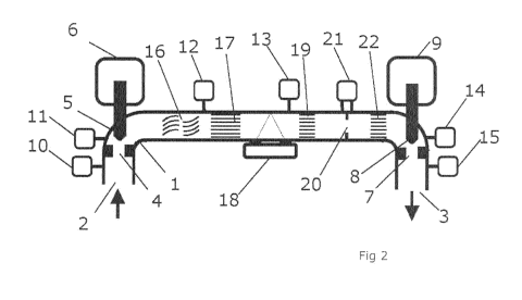
Figure 2 shows a multiphase flowmeter (MPFM) 1 according to the present
invention.
It includes a fluid inlet 2, and fluid outlet 3 connected by a suitably
pressure-rated conduit.
The fluid flow within the MPFM 1 from the inlet 2 to the outlet 3 is
controlled by an inlet
valve and an outlet valve. The inlet valve consists of an inlet actuator 6
that controls an
CA 02858448 2014-06-06
WO 2013/083721
PCT/EP2012/074694
-6-
inlet valve stem 5, and an inlet valve seat 4 towards and away from which the
inlet actuator
6 can move the inlet valve stem 5 so as to impose a variable flow restriction.
The outlet
valve likewise consists of outlet actuator 9, outlet valve stem 8 and outlet
valve seat 7,
acting in a like fashion. The inlet valve and the outlet valve are both
continuously and
precisely variable from closed to fully open, controlled by the MPFM
controller (not shown).
The valves are monotonic, so that at all points of their movement, a small
opening
movement of the valve stem will cause a small decrease in flow resistance. All
sensor
information (to be described below) is also sent to the MPFM controller.
Combined pressure/temperature sensors, 10, 11, 12, 13, 14 and 15 monitor the
pressure and temperature of the fluid in the various parts of the flowmeter
from the inlet 2
to the outlet 3. Generally, there is a combined pressure/temperature sensor
after each
flow-affecting element within the MPFM 1 so that the fluid flow can be
monitored
throughout the device. This enables remote diagnostics of developing problems,
such as
scaling, wax or sand contamination within the various sections.
Fluid entering via the fluid inlet 2 thus passes through inlet valve seat 4
and its
pressure may be reduced to a greater or lesser extent depending on the
position of the inlet
valve. This is followed by fluid mixer 16, intended to mix the fractions
within the fluid flow
in order to create a homogenous mixture. Such fluid often separates when
allowed to flow
freely, into gaseous fractions at the top (etc) and the fluid mixer 16
comprises a series of
baffles and vanes aimed at preventing this. This is followed by a series of
sequential flow
straighteners 17, 19, 22 which aim to establish or restore axial flow in the
fluid. The fluid
then exits the MPFM 1 through outlet valve seat 7 to the fluid outlet 3, with
its pressure
again being reduced to a greater or lesser extent depending on the position of
the outlet
valve.
The pressure and temperature change across the inlet valve can be obtained by
the
difference between sensors 10 and 11, the pressure and temperature change
across the
fluid mixer 16 can be obtained by the difference between sensors 11 and 12 and
the
pressure and temperature change across the outlet valve can be obtained from
by the
difference between sensors 14 and 15.
The pressure and temperature change across the inlet valve, along with the
precise
position of the inlet valve may be used to monitor and quantify the stability
of flow into the
CA 02858448 2014-06-06
WO 2013/083721
PCT/EP2012/074694
-7-
device over time. This can be achieved if the MPFM controller has knowledge of
the
relationship between the inlet valve position and the flow resistance of the
valve at that
position. This information, along with the pressure drop across the inlet
valve, enables an
approximate gross flowrate to be calculated. This gross flowrate can be used
to check the
other flowrates calculated at various points in the meter and at various
stages during the
measurement process. Significant errors or discrepancies might indicate an
error or fault
condition, while small discrepancies can be used to provide correction
factors.
The region of the flowmeter 1 between the straighteners 17 and 19 has a
homogenous axial flow. The fluid velocity in this region is determined by an
ultrasonic
flowmeter 18. This will typically be a Doppler meter of known construction,
although time-
of-flight or correlation instruments may also be used. The
pressure/temperature sensor 13
measures the pressure and temperature of the fluid in this region, which is at
the heart of
the measurement system. Between straighteners 19 and 22, the fluid passes
through an
orifice plate 20, across which the differential pressure is measured by
differential pressure
sensor 21.
In the preferred embodiment, where the flowmeter is used for accurately
measuring
3-phase flow (oil, water, gas) from a production well 108, the well 108
providing the source
of the fluid will typically be fitted with standard safety equipment such as a
subsurface shut-
in valve and surface shut in valves. The well production fluid is then routed
to the inlet 2 of
the MPFM 1, will flow through the MPFM 1, and out of the outlet 3, which is
connected to a
surface flowline 130 leading to a remote processing facility 126. It will be
noted that
pressure/temperature sensor 10 will now read the wellhead pressure, and
pressure/temperature sensor 15 will now read the flowline pressure at the
wellhead end of
the flowline 130.
It should be noted that MPFM 1 performs the function of the traditional fixed
"choke
valve" 132 in regulating the well production flowrate, as well as measuring
the 3-phase flow,
so the choke may be removed, or alternatively set to a size that limits the
well to the
highest safe rate. In routine use the MPFM controller is commanded to maintain
a certain
flow resistance equivalent to a certain size of traditional choke valve as
required for the
optimum production of the well. It should be noted that the MPFM controller
may achieve
this by setting the inlet valve fully open, and the outlet valve to the
required flow resistance.
CA 02858448 2014-06-06
WO 2013/083721
PCT/EP2012/074694
-8-
Alternatively, the MPFM controller could achieve the same overall effect by
setting the outlet
valve fully open, and setting the inlet valve to the required flow resistance.
Furthermore,
the MPFM controller can smoothly change the valves from the first combination
to the
second combination by gradually closing the inlet valve and opening the outlet
valve in such
a way that the flow restistance of the valve combination remains unchanged
during the
transition. During this time, the pressure in the MPFM between the inlet valve
and the
outlet valve will smoothly change from the inlet pressure (wellhead pressure)
to the outlet
pressure (flowline pressure). As the total flow resistance of the MPFM is
constant during
this transition, the well flow will be substantially constant, the wellhead
pressure will remain
constant and the flowline pressure will remain constant. Only the pressure
inside the MPFM
will change.
In this way, the MPFM 1 of figure 2 (comprising two variable choke valves) is
able to
establish a flow restriction equivalent to a traditional choke valve 132,
while establishing any
desired fluid pressure in the flow path between the two variable choke valves.
So far as the
flowline 130 is concerned, the situation is identical to a single choke valve
132 as shown in
figure 1. However, the MPFM controller is able to manipulate the pressure
within the MPFM
1 to any desired level falling between the wellhead pressure and the flowline
pressure.
The MPFM 1 may also be used to shut the well in. Figure 3 shows the outlet
valve
closed, and the inlet valve fully open. In this configuration,
pressure/temperature sensors
10, 11, 12, 13, 14 will all be reading the same pressure as there is no flow
through the
MPFM. This pressure will be wellhead pressure. Figure 4 also shows a fully
shut-in well, but
this time the inlet valve is closed and the outlet valve is fully open. In
this case,
pressure/temperature sensors 11, 12, 13, 14, 15 will all read the same
pressure, which will
be the flowline pressure (with no flow in the flowline). It is important to
note that in these
cases, the pressure sensors can be auto zeroed/auto calibrated, a process
where differential
offset errors are eliminated by comparing readings when all sensors are known
to be
exposed to the same pressure. In this case, the ability to set a low pressure
(the flowline
pressure) and a high pressure (the wellhead pressure) enables both zero and
gain auto
alignment to be performed, thus adjusting the calibration as necessary. In
practice, this
allows differential pressures to be adequately measured with a pair of
absolute pressure
sensors rather than an additional differential sensor in most parts of the
MPFM.
CA 02858448 2014-06-06
WO 2013/083721
PCT/EP2012/074694
-9-
Referring again to Figure 2, under normal operation, when the MPFM is
controlling at
the optimum well flowrate, the inlet valve and the outlet valve are preferably
set at a similar
flow resistance. This central setting provides half the total pressure drop
across each valve,
and hence equalises and minimises erosion of the valves.
To perform a measurement cycle, the MPFM controller gradually opens the outlet
valve and closes the inlet valve in a smooth transition to a setting which
establishes a lower
pressure in the MPFM 1, which is then held. A set of measurements are then
taken (see
below). The MPFM controller then gradually returns the inlet and outlet valve
to the central
setting which is then held, and another set of measurements are taken. In this
way, a set
of measurements are taken at two pressures. The flow through the MPFM all the
time
remains constant, because the MPFM controller is maintaining a constant flow
resistance for
the overall MPFM during the measurement cycle. It is possible to confirm that
the flowrate
has not changed during a measurement cycle by monitoring the pressure drop
across the
inlet valve with respect to the inlet valve position as described above.
A complete set of measurements thus consists of:
= Pressure P from pressure/temperature sensor 13
= Temperature T from pressure/temperatures sensor 13,
= Fluid velocity V from ultrasonic flowmeter 18
= Differential pressure DP from differential pressure sensor 21
There are thus two sets of measurements from the same sensors, designated
= Central measurement set: P1, Ti, V1, DP1
= Lower measurement set: P2, T2, V2, DP1
The calculations to be carried out are therefore as follows, based on the
following
parameters:
Measured Parameter At P1 At P2 Units
CA 02858448 2014-06-06
WO 2013/083721
PCT/EP2012/074694
-10-
Fluid velocity Fvl Fv2 m/s
Pressure P1 P2 psia
Temperature Ti T2 C
Differential Pressure DP1 DP2 psid
In addition, certain parameters need to be calculated in a straightforward
manner,
i.e.:
Volumetric flow rate at P1, Q1= Fv1.ax (ax being the conduit cross-sectional
area)
Volumetric flow rate at P2, Q2 = Fv2.ax
For the purposes of describing the system, we define P2 as being the lower of
the
two pressures, P1 and P2. Assuming that the mass flowrate is constant, the
volumetric
flowrate at P2 will therefore be greater than at P1.
The increase in the volumetric flowrate is therefore Qd = Q2 ¨ Q1
For the purpose of illustration and clarity, it is assumed in these
calculations that
liquids are incompressible, that the gas fraction behaves as a perfect gas,
and the reduction
in volume of crude oil when gas is released is negligible. Those skilled in
the art will be
aware of how such second order corrections may be applied in order to reflect
the actual
fluid properties.
For a perfect gas,
pl.v1/t1 = p2.v2/t2 --- (1
vi = k.v2 where k = p2.t1/(pl.t2)
v1 = kE/(1-k ) where expansion factor, E = v2 ¨ vi -- (1
Considering one second of flow (so we can equate volumes and flowrates), we
can
write
Volumetric flowrate of gas fraction at P1, Qg1 = k.Qd /(1-k)
CA 02858448 2014-06-06
WO 2013/083721 PCT/EP2012/074694
-11-
Hence the liquid volumetric flowrate at P1, QL1 = Q1 ¨ Qgl
The densities of the gas, oil and water fractions at different temperatures
and
pressures are measured when a reservoir is first produced, and then updated
from time to
time. This process, known as PVT analysis, is well known. From PVT analysis,
the density
of the oil and water fractions, Do, Dw are stored in the MPFM controller, and
the exact gas
density at P1 and P2, Dgl and Dg2 is calculated, using the perfect gas
equation from the
gas density at standard pressure and temperature.
The gas mass flow rate Mgl = Dgl. Qg1
The volumetric liquid fraction, FL1 = QL1/ Q1
The volumetric gas fraction, Fg1 = 1 ¨ FL1
The total fluid density can be obtained from the differential pressure across
the
orifice plate.
D1 = 2.C2. A2.DP1/Q12
where A is the cross section area of the orifice hole,
c d
/3= d2/d, ,
d2 = diameter of the orifice hole,
d1 = diameter of the conduit, and
Cd is the discharge coefficient, typically of the order of 0.6
The density of the liquid fraction DL1 can now be calculated from the
equation:
D1 = Dg1.Fg1 + DL1.FL1
where D1,Dgl, Fgl and FL1 are now known.
Finally, the oil fraction, Fol, can be calculated from the equation:
CA 02858448 2014-06-06
WO 2013/083721
PCT/EP2012/074694
-12-
FL1.DL1 = Do.Fol + Dw (FL1 ¨ Fol)
where FL1, DL1, Do, Dw are known.
Finally, the water fraction is given by Fwl = FL1 ¨ Fol
Now that fractions and the volumetric flow rates for all three phases have
been
computed, the mass flow rates for each phase can be computed as the phase
densities are
known. Hence a total mass flow rate can be computed.
The entire procedure above can then be repeated, reducing all the results to
the P2
environment.
Comparing results between the P1 environment and the P2 environment, clearly
the
fractions and volumetric flowrates will differ, due to the different
pressures. However, the
mass flowrates should be the same. In particular, the total mass flowrate
computed should
be the same for the two sets of computations.
The sensitivity of the computation to instrumentation errors from the absolute
sensors (P and T) are largely eliminated in the above computation, due to the
invention
allowing the same pressure and temperature sensor to be used in both P1 and P2
measurement sets.
The calculations are still sensitive to errors in the fluid velocity, Fv1 and
Fv2, and the
differential pressure, DP1 and DP2. These errors can largely be eliminated via
a
normalisation method. In this method, a correction velocity is speculatively
added to Fvl
(for example), and the two calculation sets are computed, and the two total
mass flowrates
calculated are compared. The process is then repeated, using the Newton-
Raphson method
adjusting the correction velocity until the two computed mass flowrates are
the identical.
This process dramatically increases the accuracy of the calculated volumetric
fractions and
velocities. Other parameter could be corrected in a similar manner, and other
correction
methods will be apparent to those skilled in the art.
Figure 5 shows a possible pressure/time profile for the apparatus. The
pressure
shown is of course the pressure within the measurement region, i.e. between
the inlet and
outlet valves 6, 9 as will be sensed by the sensors 11, 12, 13, 14. The
pressure prior to the
inlet valve and the pressure subsequent to the outlet valve 9 are of course
dictated by the
CA 02858448 2014-06-06
WO 2013/083721
PCT/EP2012/074694
-13-
combined flow resistance imposed by the two valves 6, 9 collectively, and are
controlled to
remain within the desired limits by adjustment of that collective flow
resistance. The
balance between the flow resistance imposed by the inlet valve and that
imposed by the
outlet valve 9 can be varied, and this allows the pressure in the fluid
between them to be
adjusted as desired between the upper and lower pressures either side of the
device.
Thus, the default state is one in which the pressure 50 within the device is
approximately midway between the higher pressure 52 at which the fluid arrives
from the
well, and the lower pressure 54 in the flowline 130 after the multiphase
flowmeter. As
mentioned, this places both the inlet and the outlet valves at an approximate
midway
position in which wear is minimised.
When a measurement is to be taken, the pressure, temperature, and flow rate
readings can be taken. Then, the inlet valve 6 can closed slightly and the
outlet valve 9
opened slightly, causing the pressure within the device to drop to the reduced
level 56. A
second set of pressure, temperature and flow measurements can be taken. The
inlet and
outlet valves can then be returned to their previous positions and the default
state 58 will be
resumed.
If desired, the pressure can then be set at a higher value 60 in a
corresponding
manner, to provide a third set of pressure, temperature and flow values. These
can be used
to check the results calculated from the first set and provide a confidence
level for the
results. Once this is done, the pressure can then be returned to the default
value 62 where
it will remain until the next measurement cycle 64. Further confirmatory
measurements
could be taken at the same pressures or at different pressures, as desired.
Of course, the pressure could be raised instead of being increased as shown
and as
described above. Where multiple pressure readings are taken, these could be
taken in any
desired order.
In a context where there is plenty of excess pressure, the well could be
designed
with a conventional choke valve to drop the pressure, followed by the MPFM
operating
between a reduced upper pressure and the desired flowline pressure. Such as
arrangement
still has the advantages of significantly lower instrumentation cost, and also
benefits from
the other advantages set out above.
CA 02858448 2014-06-06
WO 2013/083721
PCT/EP2012/074694
-14-
Alternatively, the valves 6, 9 could be replaced with on/off valves, each in
combination with a fixed choke valve in parallel with the respective on/off
valve. In such an
arrangement, there would always be flow through the meter, which would operate
over a
narrow pressure range. It could comprise a simplified (and therefore reduced
cost) valve
set due to the lower pressures. The on/off valves can be simple ball valves,
which could be
connected together on a single shaft driven by one actuator. If the ball
valves are placed 90
degrees out of phase, so either one or the other is on, while the other is
off, then this will
enable quite rapid toggling between the two pressures, allowing the system to
react quickly
if the flowrate is trending quickly. Indeed, such a device could toggle
pressures as
frequently as every second.
The invention can also be used with a Coriolis-type meter, arranged between
the
inlet valve and the outlet valve. A coriolis meter measures both massflow and
density. In
the manner described above, the invention derives both P1 (and Ti) and P2 (and
T2), and
the density at pressures P1 and P2 gives the gas fraction, from which it is
possible to extract
the fluid density, and hence the oil/water fractions (assuming that the
individual oil and
water densities are known. This leaves one redundant reading, i.e. the mass
flow at P1 and
at P2. As we know these are the same, they can be used to normalise the
results.
Other momentum flowmeter devices can be used in substitution for the orifice
plate,
such as a venturi or cone.
The system is flexible as to its design and could be re-engineered to a
physical
arrangement suited to use on the surface, or in a subsea context, or in a
downhole location.
The above-described system could of course be deployed in an alternative
context
(i.e. other than that of hydrocarbon extraction) where it was desired to
measure the relative
fractions in a multi-phase fluid flowing through a conduit. The high-speed
variant
mentioned above could be particularly appropriate for such use.
It will of course be understood that many variations may be made to the above-
described embodiment without departing from the scope of the present
invention.