Note: Descriptions are shown in the official language in which they were submitted.
CA 02858500 2014-06-06
WO 2013/121081 PCT/F12012/050977
1
Method for treating impurities contained in exhaust gases of
ships, ship with exhaust gas scrubber, and purification unit
Background of the invention
[0001] The invention relates to a method for treating impurities con-
tained in exhaust gases of ships, the method comprising
- scrubbing with water the exhaust gases in an exhaust gas scrub-
ber in order to reduce sulphur dioxide emissions of the exhaust gases,
- supplying wash water to be purified, containing impurities and exit-
ing from the exhaust gas scrubber, to a purification unit onboard a ship, and
- monitoring a pH value of the purified effluent, and if it is less than
6.5, it is adjusted to a value of at least 6.5, after which the purified
effluent is
discharged into a sea or returned to the exhaust gas scrubber.
[0002] The invention also relates to a ship comprising an exhaust
gas scrubber for scrubbing exhaust gases from the ship's combustion engine
and for reducing sulphur dioxide emissions, and a purification unit for
purifying
wash water to be purified and exiting from the exhaust gas scrubber.
[0003] The invention further relates to a purification unit for purifying
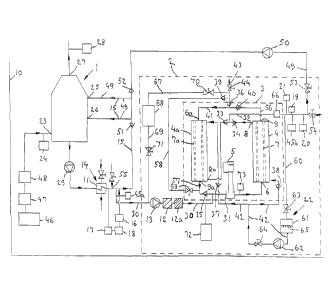
polluted wash water, i.e. effluent, exiting from an exhaust gas scrubber of a
ship.
[0004] From US 2010224070 Al a method of aforesaid kind and a
ship of the above type are known.
[0005] It is widely known to clean exhaust gases from ships' en-
gines by means of exhaust gas scrubbers. The purpose is to reduce sulphur
dioxide emissions of the exhaust gases in particular since they are
problematic .
to the environment. Sulphur dioxide emissions occur because engines of a
ship use a sulphur-containing fuel, which oxidizes during fuel combustion pro-
cess in the engine. Low sulphur fuels enable sulphur dioxide emissions to be
reduced but the low sulphur fuels are expensive. In order to be able to use
fuels whose sulphur content can be relatively high, i.e. higher than that in
so-
called low sulphur fuels, exhaust gases are scrubbed in exhaust gas scrub-
bers, enabling sulphur dioxide emissions to be dramatically reduced as com-
pared with not scrubbing the exhaust gases. An exhaust gas scrubbing pro-
cess produces wash water which contains impurities and which as such cannot
be discharged into the sea since the wash water contains a large amount of
impurities and, typically, the pH value of the wash water is also too low for
it to
be allowed to be discharged into the sea. Wash water exiting from the exhaust
2
gas scrubber may be fed back to the exhaust gas scrubber, but the wash water
cannot be recirculated "endlessly" in this way since the wash water only
becomes
more polluted the more exhaust gases are scrubbed therewith. Prior to being
dis-
charged into the sea, wash water has been diluted with water, but this does
not
eliminate the environmental problems caused by the effluent. No success has
been
achieved in purifying the wash water well enough to be able to discharge it
from the
ship into the sea. A procedure according to which the wash water is collected
to
large tanks onboard the ship wherefrom it is pumped at a harbour and
transported
to purification plants ashore is, due to the large amount of wash water, so
laborious
that it is not implementable in practice.
[0006] The above-described ways to treat exhaust gases and impurities
transferred from the exhaust gas scrubber to the wash water do not provide a
good
end result (do not eliminate impurities as efficiently as desired) or are
complicated
(e.g. the transfer of wash water from the ship to the shore) and necessitate
the use
of chemicals.
[0007] From US 6810662 B2 an arrangement is known for purifying ex-
haust gases from a combustion engine in exhaust gas scrubbers. However, the
document does not disclose how to treat wash water or reaction products
produced
when water reacts with compounds contained in the exhaust gases.
[0008] From GB 2288342 an arrangement is known for purifying exhaust
gases from a combustion engine in an exhaust gas scrubber. The document dis-
closes purification of wash water in a purification unit wherein the solid
impurity par-
ticles contained in the wash water are collected in a filter. The problem is,
however,
that the described purification unit is incapable of treating and removing
from the
wash water impurities dissolved therein, or extremely small impurity
particles, either.
Brief description of the invention
[0009] The present invention is directed to a method for treating impuri-
ties contained in exhaust gases of ships, which method is easily implementable
and
capable of efficiently eliminating impurities.
[0010] Accordingly, there is described a method for treating impurities
contained in exhaust gases of ships in order to reduce sulphur oxide
emissions, the
method comprising: scrubbing with water the exhaust gases in an exhaust gas
scrubber in order to reduce sulphur dioxide emissions of the exhaust gases,
said
scrubbing producing wash water containing impurities; supplying the wash water
CA 2858500 2018-11-27
3
containing impurities exiting from the exhaust gas scrubber, to a purification
unit on
board a ship; purifying the wash water containing impurities in the
purification unit to
produce a purified effluent, and monitoring a pH value of the purified
effluent, and, if
the pH value is less than 6.5, adjusting the pH value to at least 6.5, after
which the
purified effluent is one of discharged into a sea and returned to the exhaust
gas
scrubber; characterized in that the purification unit comprises an effluent
circuit in-
cluding at least one membrane filter, and that the wash water containing
impurities
is circulated in the effluent circuit, whereby the wash water to be purified
is filtered
using a semipermeable membrane of the at least one membrane filter to produce
the purified effluent and a residue containing the impurities, the purified
effluent be-
ing removed from the membrane filter and from circulating in the effluent
circuit
while the residue keeps on circulating in the effluent circuit.
[0011] In the method according to the invention, the impurity concentra-
tion of the effluent in the effluent circuit increases the more the more
effluent is sup-
plied to the effluent circuit, whereby the pressure difference required for
carrying out
the purification process increases. Consequently, at least some of the residue
in the
effluent circuit, highly concentrated with impurities, is at intervals removed
from the
effluent circuit, whereby preferably the effluent having a very high impurity
concen-
tration is collected in a tank for further treatment. Since the amount and
volume of
the latter effluent is only a fraction as compared with the amount of wash
water con-
taining impurities and exiting from the exhaust gas scrubber into the
purification unit
and the amount of effluent purified in the purification unit, the collection
to a tank is
easy to implement in practice. The contents of the tank are easy to deliver to
a
waste treatment plant for treating the effluent contained therein. It is to be
noted that
while cleaning the effluent circuit, it is not necessary to remove all the
water concen-
trated with impurities in one go, although this is preferable so as to make
the
amount of effluent exiting from the effluent circuit small.
[0012] In order to maintain the purification capability of the membrane fil-
ter, the membrane filter is cleaned at intervals when its semipermeable
membrane
is filled with impurities. Preferably, the cleaning is carried out by
backwashing,
whereby the impurities in the semipermeable membrane of the membrane filter
are
removed. The impurities are collected in a tank for further treatment. The
tank may
be the same tank in which the effluent removed from the effluent circuit and
having
a high impurity concentration is collected.
CA 2858500 2018-11-27
4
[0013] In order for any largish solid impurities in the effluent not to
collect
in or obstruct the semipermeable membrane of the membrane filter, the effluent
is
preferably filtered by a coarse filter and/or a micro filter prior to
supplying the efflu-
ent to the effluent circuit.
[0014]
[0015] In another aspect, there is described a ship comprising an ex-
haust gas scrubber for scrubbing exhaust gases from the ship's combustion
engine
and for reducing sulphur dioxide emissions, and a purification unit for
purifying wash
water containing impurities exiting from the exhaust gas scrubber,
characterized in
that the purification unit comprises an effluent circuit comprising a
circulation pump
and at least one membrane filter comprising a semipermeable membrane, the
circu-
lation pump being arranged to circulate the wash water containing impurities
in the
effluent circuit by feeding wash water containing impurities to an inlet end
of the
membrane filter such that the wash water containing impurities is filtered
using the
semipermeable membrane of the membrane filter and exits as purified effluent
from
an outlet of the at least one membrane filter and from the effluent circuit
while a res-
idue containing impurities is led from a discharge end of the at least one
membrane
filter back to the circulation pump and from the circulation pump again to the
inlet
end of the at least one membrane filter.
[0016] Preferably, the effluent circuit may comprise a plurality of mem-
brane filters to enable the filtering efficiency of the purification unit to
correspond
with the need to purify even large amounts of impurities and a large amount of
ef-
fluent, which in practice is the situation when large amounts of impurities
are pro-
duced during combustion process because of the large amount of sulphur
contained
in the fuel and/or because of a (large) combustion engine consuming a lot of
fuel.
An appropriate filter set is achieved by building it from membrane filters
available on
the market.
[0017]
[0018]
[0019]
[0020] The invention is based on the idea of combining with the purifica-
tion of exhaust gases implemented by means of an exhaust gas scrubber the
treat-
ment of wash water, i.e. effluent, exiting from the exhaust gas scrubber and
contain-
ing impurities in the purification unit utilizing a membrane filter comprising
a semi-
permeable membrane so as to enable impurities dissolved in the effluent and mi-
CA 2858500 2018-11-27
5
croscopically small impurities in a highly concentrated form to be removed
from the
effluent with no need to use large storage tanks for intermediate storage of
the ef-
fluent, and a vast majority of the treated waste water, purified as prescribed
by
regulations, to be pumped into the sea.
[0021] An advantage of the method and ship according to the invention is
that the utilization of the membrane filter makes the need for space required
by the
purification unit so small that the purification unit becomes easy to place
onboard a
ship. The purified water exiting from the effluent circuit can be discharged
directly
into the sea. Alternatively, the purified water may be returned back to the
exhaust
gas scrubber and recirculated. Consequently, no need exists to treat large
amounts
of wash water onshore, and no need exists to use chemicals to separate
impurities
from the wash water, either.
Brief description of the figures
[0022] The invention is now described in closer detail by means of two
examples and with reference to the accompanying drawing, in which:
Figure 1 illustrates a first embodiment for treating impurities contained in
exhaust gases, and
Figures 2a and 2b show a second embodiment of the invention for treat-
ing impurities contained in exhaust gases.
Detailed description of the invention
[0023] Figure 1 shows an exhaust gas scrubber 1 onboard a ship and a
purification unit 2 connected thereto for purifying wash water exiting from
the ex-
haust gas scrubber. Reference number 10 illustrates a ship. The ship's
combustion
engine is illustrated by reference number 46, a catalyser connected to the
combus-
tion engine 46 is designated by reference number 47, while reference number 48
designates an exhaust gas boiler. The combustion engine 46 is a diesel engine.
The catalyser 47 reduces nitrogen oxide emissions. Preferably, the catalyser
47 us-
es urea for reducing the nitrogen oxide emis-
CA 2858500 2018-11-27
CA 02858500 2014-06-06
WO 2013/121081 PCT/F12012/050977
6
sions. The structure and operation of the catalyser 47 are not discussed in
this
connection since they are known to those skilled in the art. The exhaust gases
cool down in the exhaust gas boiler 48. At the same time as the exhaust gas
boiler 48 cools down the exhaust gases, heat energy is recovered from the ex-
haust gases for the ship's various heating needs. The operation of the exhaust
gas boiler 48 is known to one skilled in the art, so the structure and
operation
of the exhaust gas boiler are not explained in closer detail herein.
[0024] In the arrangement of the figure, the exhaust gases from the
combustion engine 46 of the ship 10 are at point 23 led into the exhaust gas
scrubber 1. A measuring device 24 is used for determining the carbon dioxide
concentration (CO2 concentration) of the exhaust gases in percent by volume
prior to feeding the exhaust gases to the exhaust gas scrubber 1. Because of
the exhaust gas boiler 48, the exhaust gases arrive at the exhaust gas scrub-
ber 1 cooled down, whereby their volume and flow rate are smaller than with
no exhaust gas boiler 48 and the water demand for purifying the exhaust gas-
es decreases. Water from points 25 and 26 is sprayed onto the exhaust gases.
Preferably, the water is basic, but neutral water may also be used. The number
and location of spraying points 25, 26 may vary. The purified exhaust gases
exit from the exhaust gas scrubber 1 at point 27. A measuring device 28 is
used for determining the sulphur dioxide concentration (SO2 concentration) of
the exhaust gases exiting from the exhaust gas scrubber. When scrubbing the
exhaust gases, a ratio of S02/CO2 is measured, where SO2 is the sulphur diox-
ide concentration in percent by volume in flue gas after flue gas purification
and CO2 is the carbon dioxide concentration in percent by volume prior to flue
gas purification. By adjusting the amount of water supplied to the exhaust gas
scrubber, the operation of the exhaust gas scrubber 1 is adjusted such that
the
ratio S02/CO2 is below a given required value, less than 25 ppm S02/CO2 %
(v/v) (that is SO2 (ppm)/CO2 (% v/v)), preferably less than 10 ppm S02/CO2 %
(v/v), and most preferably less than 4.3 ppm S02/CO2 % (v/v). The scrubbing
of exhaust gases in an exhaust gas scrubber 1 being known, the procedure of
carrying out the scrubbing is not explained in closer detail herein.
[0025] When scrubbing exhaust gases, both solid impurities and
impurities dissolved in water collect in the wash water. The hot wash water
containing impurities and directed at the bottom of the exhaust gas scrubber 1
is pumped by a pump 29 to a cooling apparatus 14 comprising a heat ex-
changer 11. The pump 29 is a centrifugal type of pump, for instance. Cold raw
CA 02858500 2014-06-06
WO 2013/121081 PCT/F12012/050977
7
water is supplied to the heat exChanger 11, whereby the temperature of the hot
wash water supplied to the heat exchanger drops in the heat exchanger e.g.
from a value of about 80 C to a value of 30 C. The raw water is sea water or,
alternatively, it may be fresh water (river or lake water). The wash water is
led
along a line 15 back to the exhaust gas scrubber I.
[0026] It is ensured that the pH value of the wash water exiting from
the heat exchanger 11 and returning to the exhaust gas scrubber 1 is at least
7. In practice, this is carried out such that a measuring means 17 determines
the pH value of the water, and if the pH value measured by the measuring
means 17 is less than 7, a base is fed to the wash water by feeding means 16
so that a pH value of at least 7, preferably 7.5, is achieved. The base to be
used is e.g. lye, i.e. sodium hydroxide (NaOH), or another neutralising sub-
stance. Control means 18 control preferably automatically the operation of the
feeding means 16. The feed rate of wash water to the exhaust gas scrubber 1
is in the order of 100 to 1000 m3/h, mostly depending on the engine power of
the ship. In small engines in particular, the feed rate may be less than 100
m3/h, for instance 40 to 100 m3/h. The wash water feed rate is typically 20 to
50 m3/MWh. Thus, the water feed rate for a heavy oil operated diesel engine of
about 6000 kW power may typically be 30 to 300 m3/h, and more typically 100
to 250 m3/h, when the wash water feed pressure is 3 to 5 bar. It is possible
that
the feed pressure is higher than this, in which case the wash water feed rate
may be reduced.
[0027] When necessary, more water is fed to the line 15 leading to
the exhaust gas scrubber 1. Reference number 55 designates the water feed-
ing point to the line 15. The water may be fresh water or salt water. The line
15
may also be fed with water purified in the purification unit 2 to be described
be-
low, and this water is led along a line 49 (outlet line) to the exhaust gas
scrub-
ber 1, resulting in internal circulation.
= [0028] Downstream of the heat exchanger 11, a line 30 starts for
the purification unit 2 for purifying the wash water containing impurities,
i.e. the
effluent. A feed pump 13 feeds effluent via a coarse filter 12 to an effluent
cir-
cuit 3. The effluent feed rate is about 0.1 to 5 m3/h. The magnitude of the
feed
rate highly depends on the ship's engine power and the sulphur concentration
of the fuel. Preferably, the feed pump 13 is a displacement type pump (posi-
tive-displacement pump), and it is arranged to produce a pressure of 0.1 to 5
bar in the line 30 downstream of the feed pump. The pressure may also be
CA 02858500 2014-06-06
WO 2013/121081 PCT/F12012/050977
8
more than 5 bar, for instance 10 bar. The advantage of a displacement pump,
which is e.g. of the eccentric screw pump type, is that it is highly resistant
to
dirt and corrosion and does not much mix the medium it is pumping. The pres-
sure of the effluent in the line 30 upstream of the feed pump 13 is 0.1 to 10
bar, e.g. 3 to 5 bar, but may be higher than this. The pore size of the coarse
fil-
ter 12 is selected such that solid impurity particles larger than 5 pm in size
are
filtered out; particles smaller than this pass through the filter. Typically,
the
pore size of the coarse filter 12 is selected such that impurity particles at
least
40 pm in size, e.g. at least 50 to 100 pm, are filtered out. Such impurity
parti-
cles include rust scales, large soot particles, and possible salt crystals.
The
coarse filter 12 is preferably a wire mesh filter. After the coarse filter 12,
a se-
cond filter 12a is arranged for filtering impurity particles whose size is
larger
than 0.4 pm. The pore size of the filter 12a is selected such that it filters
out
solid impurity particles whose size is larger than e.g. 10 pm. The filter 12a
may
be called a micro filter. The filter 12a filters inter alia small soot
particles and
possible small salt crystals contained in the effluent. It is thought that the
filter
12a reduces the need to clean membrane filters 4, 4a included in the purifica-
tion unit 2. The filters 12, 12a may comprise cleanable or replaceable filter
el-
ements. The coarse filter 12 may alternatively be an automatic, self-cleaning
filter.
[0029] The effluent that has undergone the above-described prelim-
inary filtration is led to the effluent circuit 3. The effluent circuit 3
comprises two
series-connected membrane filters 4, 4a which comprise a semipermeable
membrane 7, 7a serving as a film. The membrane filters 4, 4a are capable of
filtering impurities whose size is less than 0.1 pm. The membrane filters are
commonly commercially available filters. They have an elongated frame struc-
ture made of a ceramic material and comprising a plurality of drillings or
chan-
nels extending from an outlet end 6, 6a of the membrane filter to a discharge
end 9, 9a of the membrane filter. The material of the ceramic frame is e.g.
sin-
tered alumina (Al2O3), titanium oxide (TiO2), silicon oxide (SiO2) or
zirconium
oxide (ZrO2). For the sake of simplicity, only two drillings are illustrated
in the
figure in broken line. The diameter of the drillings is e.g. 3 to 4 mm, and
the
length of the membrane filter is e.g. about 1000 mm. The active layers (mem-
branes) of the membrane filter are typically made of the same oxides as the
frame structure. The active layer is thus e.g. titanium oxide (TiO2) if the
mem-
brane filter is of the micro filter type, and may be e.g. zirconium oxide
(ZrO2) if
CA 02858500 2014-06-06
WO 2013/121081 PCT/F12012/050977
9
the filter is of an ultrafilter type or a nanofilter type. The active layer
may also
consist of sintered alumina (A1203) and silicon oxide (SiO2) or combinations
of
said oxides. Instead of an oxide layer, it is feasible that an active layer is
made
of an appropriate silicate or carbide. The material constituting a semipermea-
ble membrane is porous so that it enables selective permeation of water mole-
cules contained in the effluent on condition that the pressure is sufficiently
high. The material constituting the semipermeable membrane does not, how-
ever, enable permeation of compounds dissolved in the effluent, such as dis-
solved carbon compounds, hydrocarbon compounds, nitrogen compounds
(such as nitrates and nitrites) and sulphur compounds (such as sulphates and
sulphites) and extremely small solid impurity particles, so these keep on
circu-
lating in the effluent circuit 3. Depending on the type and pore size of the
membrane filter, the membrane filters 4, 4a may be used for filtering out
parti-
cles whose size is as small as few nanometres only. Since the size of a water
molecule is only about 0.3 nm, it penetrates the semipermeable membrane of
the membrane filter.
[0030] Preferably, an ultrafilter or a nanofilter and, if permeation of
very small matter is to be prevented, possibly a reverse osmosis filter, may
be
used as the membrane filter 4, 4a. The filtration capacity of a nanofilter is
with-
in a range of about 0.0008 to 0.008 pm (molecular weight of about 200 to
15000 being filtered out) while a reverse osmosis filter passes therethrough
matter having the size of less than about 0.0011 pm (about 1 nm) whose mo-
lecular weight is within a range of 1 to 400. Metal ions can be filtered out
by the
reverse osmosis filter but nanofilters pass metal ions therethrough. The ad-
vantage of nanofilters is that they operate at a lower pressure than the
reverse
osmosis filter. The pore size of the membrane filter 4, 4a is selected such
that
it meets the requirements set for water purification. Those skilled in the art
are
capable of selecting the membrane filter on the basis of their common
knowledge or by trial; the selection requires no unreasonable effort. The
physi-
cal implementation of the membrane filter may vary greatly; it may be in
spiral
form (comprising several fibre layers), in tubular form, etc. A filter manufac-
tured by Pall Filtersystems GmbH under the trade name SCHUMASIV (type
Pall ¨ MF 0050T6021) with a pore size of 0.05 pm may be used as the mem-
brane filter 4, 4a, for instance.
[0031] The effluent circulates in the effluent circuit 3 by means of a
circulation pump 5. The effluent circulation rate in the effluent circuit is
50 to
CA 02858500 2014-06-06
WO 2013/121081 PCT/F12012/050977
110 m3/h, e.g. 50 to 70 m3/h, depending inter alia on the number of membrane
filters 4, 4a; and in order to achieve the optimal flow rate (in unit m/s), as
far as
the operation of the membrane filters is concerned, the pressure in the
effluent
circuit 3 is e.g. 2 to 7 bar, and may typically be 3 to 5 bar, but more than 7
bar,
e.g. a range of 7 to 100 bar may be feasible. The optimal flow rate may be 4
to
6 m/s, for instance. From outlets 8, 8a of the membrane filters 4, 4a, through
the semipermeable membrane 7, 7a, a filtrate, which is purified effluent, is
dis-
charged into a line 32. The rate of flow of purified effluent in the line 32
is 1
m3/h, for instance. The rate of flow highly depends on the engine power of the
ship and the efficiency of the purification unit 2, which has to be
dimensioned
to correspond with the purification demand. The rate of flow in the line 32
may
thus vary greatly, e.g. 0.5 to 5 m3/h. From the discharge end 9 of the mem-
brane filter 4 a residue, i.e. effluent containing impurities, exits into the
inlet
end 6a of the membrane filter 4a, and from the discharge end 9a of the mem-
brane filter 4a a residue, i.e. effluent containing impurities, exits into an
inlet
end 31 of the circulation pump 5.
[0032] It is feasible that while circulating the effluent, the membrane
7, 7a is subjected to ultrasounds at a frequency of 30 to 70 kHz, e.g. 50 kHz,
and/or to vibration at a frequency of 50 to 1000 Hz in order to improve the
sep-
arating power (efficiency of purification) of the membrane filter. The
membrane
can be made to vibrate by placing it in a vibrating fixture or housing (not
shown).
[0033] Reference numbers 33 to 40 designate return valves. The
return valves 33 to 40 ensure that the fluid is not allowed to circulate in a
wrong direction as far as the operation of the purification apparatus is con-
cerned.
[0034] At intervals, the effluent circuit 3 is cleaned of effluent and
collected impurities since the effluent becomes concentrated with impurities
as
the effluent circulates in the effluent circuit 3 and purified effluent exits
from the
line 32. When the effluent circulates in the effluent circuit 3, solid
microscopi-
cally small impurities collect in the semipermeable membranes 7, 7a of the
membrane filters 4, 4a. The semipermeable membranes 7, 7a of the mem-
brane filters 4, 4a gradually become filled with the solid, extremely small
impu-
rities, such as soot particles, after which their filtration capacity is poor
and
they have to be cleaned. Impurities dissolved in water do not collect in the
membrane filters 4, 4a but keep on circulating in the effluent circuit 3. New
ef-
CA 02858500 2014-06-06
WO 2013/121081 PCT/F12012/050977
11
fluent is fed from the line 30 to the effluent circuit 3 as purified effluent
exits
from the line 32 into the line 49 wherefrom the water is forwarded to the ex-
haust gas scrubber 1 and/or via a valve 54 into the sea. When the pressure dif-
ference becomes disadvantageously large for carrying out membrane filtration
and the impurity concentration of the effluent circulating in the effluent
circuit
has become high, the effluent circuit 3 is cleaned by emptying it of effluent.
[0035] The cleaning of the effluent circuit 3 by emptying is carried
out by leading purified water from the line 32 via a line 60 to a water tank
61
wherefrom along a line 42 water is led to the effluent circuit 3, to the
"clean
side" of the membrane filters 4', 4a'. Alternatively, the effluent circuit 3
may be
emptied by using water to be obtained from a source other than the purified
water exiting from the effluent circuit. Since water is applied to the "clean
side"
of the membrane filters 4, 4a, it may be said that the effluent circuit is
subject-
ed to backwash ing. Reference number 62 designates a pump used for increas-
ing the pressure in the line 42 to be higher than the pressure in the line 60.
The pressure in the line 42 is preferably 6 to 12 bar, for instance 8 bar. The
line 42, the pump 62, and the water tank 61 together constitute a washing de-
vice 22. Water led from the line 42 to the "clean side" of the membrane
filters
4, 4a at a relatively high pressure (preferably 6 to 12 bar) removes
impurities
collected in the membranes 7, 7a of the membrane filters. When purified water
(or another appropriate fluid) is fed by the washing device 22 via the line 42
towards the membranes 7, 7a in a direction which is opposite to the direction
in
which the effluent purified of impurities flows through the membranes 7, 7a,
the
solid impurities collected in the membranes 7, 7a can be removed and be dis-
posed of via the line 43. Preferably, the water (or another fluid) may be sup-
plied as pressure pulses, which enhances the removal of impurities from the
membranes 7, 7a. While the washing device 22 empties the effluent circuit 3 of
effluent containing a large amount of dissolved impurities, it simultaneously
cleans the membranes 7, 7a of the membrane filters 4, 4a of solid impurities.
In order to improve the cleaning efficiency, the water may be led to the
effluent
circuit heated, e.g. to a temperature of 30 to 70 C. The water tank 61 is
prefer-
ably provided with a heating device 65, e.g. electric resistors, for heating
the
water. The volume of the water tank 61 is e.g. 50 to 150 L. Preferably, the wa-
ter tank 61 is heat-insulated. A valve 63 is used for controlling the access
of
water into the water tank 61. A valve 64 is used for controlling the access of
water into the membrane filters 4, 4a. While cleaning the effluent circuit 3,
the
CA 02858500 2014-06-06
WO 2013/121081 PCT/F12012/050977
12
circulation pump 5 is stopped. When the washing device 22 feeds water to the
effluent circuit 3 including its membrane filters 4, 4a, the concentrated
effluent
in the membrane filters 4, 4a and in the lines of the effluent circuit can be
led
from the discharge end 9 of the membrane filter 4 along a line 56 to the line
43
and, correspondingly, led from the inlet end 6a of the membrane filter 4a
along
the line 41 (and possibly led from the discharge end 9a' of the membrane
filter
4a' along a line 58) to the line 43, and removed from the line 43 for further
treatment. Alternatively or additionally, the effluent in the membrane filter
4a
may be led from the discharge end 9a along the lines 57 and 58 to the line 43,
and removed from the line 43, in which case a valve 59 is open. A valve 44 of
the line 43 and the valve 59 of the line 58 are normally, when effluent is
circu-
lated in the effluent circuit 3, closed but the valve 44 and, when desired,
also
the valve 59 is/are opened when effluent is to be removed from the line 43 or
when the effluent circuit is to be cleaned (by the cleaning device 22) of
effluent
and solid impurities.
[0036] Instead of purified water obtained from the line 32, pressur-
ized air or some other appropriate fluid, such as nitrogen, may be used for
cleaning the effluent circuit 3. The volume of the effluent circuit 3 is e.g.
100 to
1000 L, typically 50 to 500 L. The volume depends on the engine power of the
ship and the efficiency of the purification unit 2. For a heavy oil operated
diesel
engine of about 6000 kW power, for instance, the volume of the effluent
circuit
is about 60 L.
[0037] The described backwashing and the related cleaning of the
membrane filters 4, 4a and emptying of the effluent circuit of effluent via
the
line 43 are carried out at intervals as necessary when the pressure difference
so requires. Backwash procedures may be carried out e.g. four times per hour.
The concentrated effluent containing impurities is emptied via the line 43 to
a
collection tank (not shown in Figure 1, although a tank 68 may be called a
kind
of collection tank) acting as an intermediate storage whose contents may be
treated ashore. The collection tank may be small since the amount of effluent
_ exiting from the line 43 is quite small but it contains a very large amount
of im-
purities. Among other things, the impurity concentration and feed rate (in
unit
m3/h) of the effluent flowing in the line 30, the volume of the effluent
circuit 3,
the efficiency and number of membrane filters 4, 4a, the purity requirement
set
for the water exiting from the line 32 have an influence on how often back-
washing is to be performed. It is feasible that in association with the
cleaning of
CA 02858500 2014-06-06
WO 2013/121081 PCT/F12012/050977
13
the membranes 7, 7a they are subjected to ultrasounds at a frequency of 30 to
70 kHz, e.g. 50 kHz, and/or to vibration at a frequency of 50 to 1000 Hz in or-
der to enhance the cleaning thereof.
[0038] The purification unit 2 enables the concentrated effluent to
be transferred from the line 43 via a line 67 to the sludge receptacle 68
which
serves as a kind of intermediate storage or buffer storage for sludge. The con-
centrated effluent may be fed from the sludge receptacle 68 along a line 69
back to the effluent circuit 3 wherein the effluent is again made to circulate
through the membrane filters 4, 4a. In such a case, a vast majority of the con-
centrated effluent is purified such that purified water is led to the line 32
while
water that has become even more concentrated with dirt is led to the line 43.
Such additional treatment of concentrated effluent enables a very efficient
puri-
fication of effluent to be achieved such that the dirt can be concentrated
into a
very small volume which takes very little space and which is easy to transport
to final treatment. Thus, the sludge receptacle 68 may be a detachable tank to
be at intervals taken ashore for hazardous waste treatment. A valve 70 is con-
nected to the line 67 while a valve 71 is connected to the line 69.
[0039] It is feasible that the effluent circuit 3 is cleaned such that it
is not emptied completely. In such a case, only smaller amounts of effluent
are
removed from the effluent circuit. A need to frequently remove small amounts
of effluent arises if the semipermeable membranes 7, 7a of the membrane fil-
ters clog up quickly with extremely small impurities that hinder the operation
of
the membrane filter. If small amounts of effluent are frequently removed from
the effluent circuit 3, the total amount of effluent exiting from the line 43
is larg-
er than if substantially all effluent, highly concentrated with impurities, is
re-
moved from the effluent circuit 3 infrequently. In order to keep the total
amount
of effluent exiting from the line 43 small, the effluent circuit 3 and the
semiper-
meable membranes 7, 7a are cleaned only when necessary, i.e. when they no
longer operate appropriately. If the need to clean the semipermeable mem-
branes 7, 7a is insignificant, at least a vast majority of the effluent
contained in
the effluent circuit 3 is removed at long intervals, rather than only in small
amounts and at short intervals.
[0040] In addition to the above-described cleaning comprising
backwashing, it is preferable to clean the effluent circuit 3 with a cleaning
agent, which may be a basic cleaning agent. Cleaning with a cleaning agent
cleans the effluent circuit more efficiently than a mere backwashing. The
clean-
CA 02858500 2014-06-06
WO 2013/121081 PCT/F12012/050977
14
ing with a cleaning agent is performed much more seldom than the above-
described backwash procedures. In Figure 1, reference number 72 designates
a cleaning agent reservoir connected to the effluent circuit. The volume of
the
cleaning agent reservoir 72 is e.g. 100 L. The cleaning agent reservoir is con-
nected to the line 30, by means of which a cleaning agent is applied to a
"dirty
side" of the membrane filters. A need to clean the effluent circuit 3 arises
when
the pressure in the effluent circuit 3 rises above a certain level.
Consequently,
the pressure of the effluent circuit 3 is monitored by a measuring device 73.
When the measuring device 73 indicates that the pressure has risen above a
certain level, a cleaning agent is fed from the cleaning reservoir 72 to the
efflu-
ent circuit 3. Alternatively, the effluent circuit 3 may be cleaned at certain
de-
termined intervals, in which case no measuring device 73 is necessary. Since
those skilled in the art know how to design the necessary feeding arrange-
ments, no arrangement for feeding a cleaning agent to the effluent circuit is
explained in closer detail herein. Prior to feeding the cleaning agent to the
ef-
fluent circuit 3, it is preferable to empty the effluent circuit of effluent.
[0041] A measuring means 19 is connected to the line 32 for meas-
uring the pH value of the purified effluent. If the pH value is below 6.5, a
feed
device 20 is used for a base, e.g. lye, to the exiting water so that the pH
value
is at least 6.5. Temporarily, in manoeuvring situations, when the load on the
combustion engine varies, it may be allowable that the pH value of the
purified
water differs by about two pH units from the pH value of the water taken
onboard the ship.
[0042] A measuring means 21 is also connected to the line 32 for
determining turbidity of the purified effluent. Preferably, the turbidity must
not
on average (measured in a time period of more than 15 minutes) be more than
25 FNU above the value of the water taken onboard the ship, where FNU is
the unit for turbidity and refers to "Formazin Nephelomeric Units". Said
turbidity
may also be given as a value of 25 NTU, where NTU refers to "Nephelometric
Turbidity Units". The purification unit 2, the filters 12, 12a, 4, 4a included
there-
in and the operation parameters of the purification line are adapted to fulfil
a
required turbidity value. The turbidity of water may be measured by a device
called a nephelometer which comprises a detector for measuring how small
particles contained in water scatter light. The detector is set to a side of a
light
beam. If the water contains a large amount of small particles, more light is
re-
flected into the detector than if the amount of small particles is small. A
cali-
CA 02858500 2014-06-06
WO 2013/121081 PCT/F12012/050977
brated nephelometer measures the turbidity of water in NTU. The ISO 7027
standard provides a test method for determining the turbidity of water.
[0043] The purified effluent is discharged into the sea and/or fed
back to the exhaust gas scrubber 1 via the line 49. When necessary, a pump
50 increases the pressure of the water in the line 49 such that the pressure
of
the water fed to the line 15 as described above does not exceed the pressure
in the line 49. If it is desired that all purified effluent is led to the
exhaust gas
scrubber 1, the valve 54 in the line 32 has to be closed. When necessary, the
feed device 20 is used for ensuring that the pH value of the purified water is
appropriate (pH about 7) to be fed to the exhaust gas scrubber 1. If it is
desired
that all purified effluent is discharged into the sea, a valve 53 in the line
49 has
to be closed. Preferably, a junction of the lines 32 and 49 is provided with a
three-way valve (not shown) for adjusting the magnitude of proportions of the
purified water to be fed back to the exhaust gas scrubber 1 and to be dis-
charged into the sea. The three-way valve is preferably automatic.
[0044] The purification unit 2 also purifies polycyclic aromatic hy-
drocarbons (PAH). Preferably, the operation of the purification unit 2 is de-
signed and dimensioned such that the PAH concentration of the purified efflu-
ent is not more than 50 pg/L above the PAH concentration of the water taken
in, whereby said value 50 pg/L relates to a 45 t/MWh effluent rate, where MW
refers to driving a combustion engine at a power which is 80% of the maximum
power of the combustion engine. Reference number 45b designates a measur-
ing device for determining the PAH concentration in the purified effluent,
i.e. in
the line 32, while reference number 45a designates a measuring device for de-
termining the PAH concentration in the line 30 prior to the purification unit
2
and the effluent circuit 3. The measuring devices 45a, 45b are measuring de-
vices based on fluorescence when the effluent rate exceeds 2.5 t/MVVh, and
measuring devices based on ultraviolet light or the like when the effluent
rate is
below 2.5 t/MVVh. Preferably, the measuring devices should be in accordance
with the ISO 7027:1999 standard.
[0045] Many metals contained in the effluent, such as arsenic, cad-
mium, chrome, copper, lead, nickel, zinc, vanadium, molybdenum and manga-
nese, are detrimental to the environment. The purification unit 2 enables
solid
compounds containing said metals, i.e. particles, to be removed from the efflu-
ent such that the filtrate exiting from the line 32 does not contain them. The
metal compounds dissolved in the effluent that are not purified in the mem-
CA 02858500 2014-06-06
WO 2013/121081 PCT/F12012/050977
16
brane filters 4, 4a may be removed from the purified effluent exiting from the
membrane filters by ion exchange. The purified effluent is then led to an ion
exchange apparatus, which is illustrated by reference number 66. The ion ex-
change apparatus ,comprises one or more ion exchange pastes or resins to
remove dissolved metal ions. Ion exchange occurs when the water being
treated passes through the ion exchange paste or resin. Ion exchange pastes
or resins suitable for removal of metal cations are highly acidic cation
resins
and chelating cation resins, for example. The ion exchange paste or resin used
may be regenerated or replaced when necessary. The ion exchange apparatus
66 enables matter that cannot be reached by a nanofilter, such as metal ions,
nitrates and nitrites, to be purified.
[0046] The purification unit 2 is designed to purify nitrates (NO3")
contained in the effluent such that the amount of nitrates does not exceed an
amount NOx in exhaust gases associated with a 12% reduction of the amount
NO in the exhaust gases, or does not exceed 60 mg/I when the rate of efflu-
ent removal is 45 t/MVVh, where the greater one of said conditions is the de-
termining one. Nitrites (NO2") contained in the effluent are also purified.
[0047] Typically, the sulphur compounds contained in the effluent
are in sulphate form (S042") so, being harmless, they may be discharged into
the sea water and need not be purified. Nevertheless, they are removed from
the line 43 in connection with backwashing. The effluent also contains a small
amount of sulphites (S032").
[0048] It is known that the above-described arrangement enables
the exhaust gases from a ship's engine to be purified so that the sulphur and
nitrogen compounds remain below the given maximum values. The scrubbing
of exhaust gases produces wash water whose pH, PAH and composition may
be as follows:
pH 7.1
PAH 22 pg/L
water <75 wt%
sulphates (S042") <25 wt%
nitrates (NO3") <0.2 wt%
nitrites (NO2) <0.2 wt%
metals, in total <0.0001 wt% (e.g. 65500 pg/L V, 8000 pg/L
Ni, 1100 pg/L Mo, 240 pg/L Zn, 137 pg/L Cr, 130 pg/L Cu, 95 pg/L
Mg, 58 pg/L AS, 2 pg/L Pb, 1 pg/L Cd, and Hg < 0.2 pg/L)
CA 02858500 2014-06-06
WO 2013/121081 PCT/F12012/050977
17
hydrocarbons in total <0.0001 wt%.
[0049] The composition depends on the engine's running condi-
tions, the fuel used, and the running conditions of the exhaust gas scrubber
(the type, amount and temperature of the water).
[0050] A person skilled in the art will appreciate that nitrates can be
purified in the purification unit 2 well enough for the aforementioned require-
ment to be met, according to which the amount of nitrates does not exceed the
amount NO in the exhaust gases associated with a 12% reduction of the NOx
amount in the exhaust gases, or does not exceed 60 mg/L when the rate of ef-
fluent removal is 45 t/MWh, where the greater one of said conditions is the de-
termining one. Sulphates can also be purified, although they could be dis-
charged into the sea without purification. Nitrites are also purified. The
filters
12, 12a, 4, 4a included in the purifying unit 2 ensure that solid metal com-
pounds are purified while the ion exchange apparatus 66 ensures that dis-
solved metal compounds are purified.
[0051] Figures 2a and 2b show an embodiment of the invention.
Figure 2b shows a purification unit 2' to be connected to a ship 10' shown in
Figure 2a such that when connected to the ship the purification unit is
located
onboard the ship. The reference numbers of the components in Figures 2a and
2b roughly correspond with those in Figure 1 when the function of the compo-
nents is the same or almost the same. The embodiment of Figures 2a and 2b
differs from the embodiment of Figure 1 inter alia such that it comprises a
tank
107' arranged between an exhaust gas scrubber 1' and an effluent circuit 3'
and communicating with both the exhaust gas scrubber 1' and a sludge recep-
tacle 68'. The sludge receptacle 68' may be called a backwash tank. From the
sludge receptacle 68' sludge may be led to a sludge receptacle 68a' which
ashore is transferred to a waste treatment plant. The embodiment of Figures
2a and 2b further comprises a tank 113' arranged downstream of the exhaust
gas scrubber 1' for receiving polluted wash water exiting from the exhaust gas
scrubber. The tank 113' communicates with the ship's technical water, and pu-
rified water purified by the purification unit 3' may be fed thereto. A line
(not
shown) may be arranged for leading the purified effluent from a line 49' to a
line 15' in a manner similar to that shown above in the embodiment of Figure
1.
The line 49' may be provided with a valve arrangement (not shown) to enable
the feeding of purified water to be controlled alternatively to the exhaust
gas
scrubber 1' (via the aforementioned line not shown and the line 15') or to the
CA 02858500 2014-06-06
WO 2013/121081 PCT/F12012/050977
18
tank 113', or to both the exhaust gas scrubber 1' and the tank 113' simultane-
ously. Reference number 114' designates a pump for feeding, when neces-
sary, sea water to the purified water exiting from the ship 10'. When
necessary,
the pump 114' is used for diluting the purified effluent prior to discharging
it into
sea water.
[0052] In the following, it will be explained how in the embodiment of
Figures 2 the membranes 7', 7a' of the membrane filters 4', 4a' are cleaned
with a chemical cleaning agent in order to clean them of impurities and how
the
membrane filters are subjected to intermediate washing. The pump 13' is
stopped while the membranes 7', 7a' are being cleaned. Prior to cleaning the
membranes 7', 7a', the dirty side of the membrane filters 4', 4a' is emptied
of
effluent. The emptying may be carried out with pressurized air or by a
drainage
pump 100' or by both the pressurized air and the drainage pump 100'.
Emptying the dirty side of the membrane filters by means of pres-
surized air
[0053] Pressurized air is applied from a pressurized air line 106' to
the clean side of the membrane filters 4', 4a', whereby the air passes from
the
clean side of the membrane filters to their dirty side and the effluent is led
to
the sludge receptacle 68' by opening valves 101', 102', 109'.
Emptying the dirty side of the membrane filters by means of a drain-
age pump
[0054] The drainage pump 100' is used for sucking at the lowest
point of the circulation, and the effluent is led to the sludge receptacle
68'. For
the emptying, a ventilation valve 103' provided at an upper part of the
circula-
tion must be opened.
Emptying the dirty side of the membrane filters by means of pres-
surized air and a drainage pump
[0055] The drainage pump 100' is used for sucking at the lowest
point of the circulation, and the effluent is led to the sludge receptacle
68'. For
CA 02858500 2014-06-06
WO 2013/121081 PCT/F12012/050977
19
the emptying, the ventilation valve 103' provided at the upper part of the
circu-
lation must be opened.
Filling the membrane filters for cleaning, and cleaning with a basic
cleaning agent
[0056] After the membrane filters 4', 4a' have been emptied, the fill-
ing of the membrane filter for cleaning is started. The ventilation valves
103',
110' of air venting lines to an expansion tank 104' are opened. The membrane
filters 4', 4a' are filled with heated technical water supplied from a line
111',
and simultaneously a basic cleaning agent is dispensed from a basic cleaning
agent reservoir 72a' by means of a cleaning agent feed pump 108'. Reference
number 112' designates a heater. The membrane filters 4', 4a' are filled up
when a level switch 105' connected with the expansion tank 104' indicates
this.
The cleaning is started by starting a circulation pump 5'.
Emptying and intermediate washing of the membrane filters
[0057] After cleaning, the membrane filters 4', 4a' are emptied as
explained above, after which the membrane filters are filled and washed as
explained above with the exception that no cleaning agent is used.
[0058] After the aforementioned treatment the membrane filters 4',
4a' have been cleaned, and the purification process of effluent from the ex-
haust gas scrubber may continue by starting the feed pump 13' and the circu-
lation pump 5'.
[0059] When necessary, the membrane filters 4', 4a' may also be
cleaned with an acidic cleaning agent. The cleaning with an acidic cleaning
agent is carried out as explained above, but instead of a basic cleaning agent
an acidic cleaning agent obtained from an acidic cleaning agent reservoir 72b'
is used. After the membrane filters 4', 4a' have been cleaned with the acidic
cleaning agent, the membrane filters are emptied and subjected to intermedi-
ate washing as described above.
[0060] Preferably, the purification unit 2' according to the invention
may be a transportable container-like unit since such a structure is quite
easy
to connect to old, already existing ships as retrofitting. In Figure 2,
reference
CA 02858500 2014-06-06
WO 2013/121081 PCT/F12012/050977
identification K1 designates a connecting means KI for connecting the purifi-
cation unit 2' to an effluent pipe 30' coming from the ship's exhaust gas
scrub-
ber 1', reference identification K2' designates a connecting means for connect-
ing the purification unit to the ship's water distribution circuit, and
reference
identification K3' designates a connecting means for connecting the
purification
unit to the ship's pressurized air circuit so as to enable pressurized air to
be
applied to the clean side of a membrane filter. It is feasible that components
designated by reference numbers 19', 21', 45' and 20' are located inside the
container-like unit.
[0061] EXAMPLE. The method and purification unit according to the
invention were used for treating effluent from an exhaust gas scrubber of a
heavy oil operated diesel engine of about 6000 kW power. The turbidity, pH
and composition of the effluent prior to purification were: Turbidity 87 FNU,
pH
12, nitrates (NO3") 5.0 mg/L, nitrites (N0i) 5.3 mg/L, sulphates (S042') 940
mg/L, sulphites (S032-) <20 mg/L, and PAH compounds 84 pg/L in total. The
effluent was fed to the purification unit at about 1.5 m3/h through a coarse
filter
with a pore size of 35 pm. The effluent circulated in the effluent circuit
provided
with two series-connected membrane filters with a pore size of 50 nm. The flow
rate in the effluent circuit was about 6 m/s and the pressure was 3 bar. The
turbidity, pH and composition of the effluent after purification were:
Turbidity
1.6 FNU, pH 12, nitrates (NO3") 4.8 mg/L, nitrites (NO2) 5.1 mg/L, sulphates
(S042") 380 mg/L, sulphites (S032) < 10 mg/L, and PAH compounds 6.9 pg/L in
total.
[0062] In summary, it can be stated that the above-described ar-
rangement enables exhaust gases to be purified and wash water to be treated
such that even strict requirements and recommendations are met, e.g. those
set forth in the IMO resolution MEPC.184(59) ("GUIDELINES FOR EXHAUST
GAS CLEANING SYSTEMS") issued in 2009.
[0063] It is clear that the arrangement requires some experimenting
and adjusting so as to make the operation of the purification device as
desired
and meet the requirements set.
[0064] In the following, a list is presented to explain the meaning of
the reference numbers used in Figures 1 and 2:
1, 1' exhaust gas scrubber
=
2, 2' purification unit
3, 3' effluent circuit
CA 02858500 2014-06-06
WO 2013/121081 PCT/F12012/050977
21
4, 4a, 4', 4a' membrane filter (a filter containing a semipermeable
membrane)
5, 5' circulation pump
6, 6' inlet end of the membrane filter 4, 4'
6a, 6a' inlet end of the membrane filter 4a, 4a'
7, 7' semipermeable membrane
7a, 7a' semipermeable membrane
8, 8' outlet of the membrane filter 4, 4'
8a, 8a' outlet of the membrane filter 4a, 4a'
9, 9' discharge end of membrane filter 4, 4'
9a, 9a' discharge end of the membrane filter 4a, 4a'
10, 10' ship
11, 11' heat exchanger
12, 12' coarse filter
12a micro filter
13, 13' feed pump
14, 14' cooling apparatus
15, 15' line
16, 16' base feeding means
17, 17' measuring means for determining pH value of effluent exiting
from the exhaust gas scrubber 1
18, 18' control means for controlling the base feeding means 16
19, 19', 19a' measuring means for determining pH value of purified
effluent
20, 20' feed device for feeding a base to purified effluent
21, 21' measuring means for determining turbidity of purified water
22 backwash system
23, 23' exhaust gas entrance point
24, 24' measurement device for measuring CO2 value of exhaust
gases
25, 26, 25', 26' water feeding point
27, 27' discharge point of purified exhaust gases
28, 28' measurement device for determining SO2 value of exhaust
gases
29, 29' pump
30, 30' line (effluent line)
CA 02858500 2014-06-06
WO 2013/121081 PCT/F12012/050977
22
31, 31 inlet end of the circulation pump 5, 5'
32, 32' line
33 to 40 return valves
41, 42, 43 line
44 valve
45a, 45b, 45a', 45b' measurement device for determining PAH con-
centration
46, 46' diesel engine
47, 47' catalyser
48, 48' exhaust gas boiler
49, 49' line (outlet line)
50, 50' pump
51, 52 return valve
53, 54, 53', 54' valve
55 water feeding point
56, 57, 58 line
59 valve
60, 60' line
61, 61' water tank
62, 62' pump
63, 64, 63', 64' valve
65 heating device
66, 66' ion exchange apparatus
67, 67' line
68, 68', 68a' sludge receptacle
69, 69 line
70, 70' valve
71, 71' valve
72, 72a', 72b' cleaning agent reservoir
73, 73' measurement device
100' drainage pump
101', 102' valve
103' ventilation valve
104' expansion tank
105' level switch
106' pressurized air line
CA 02858500 2014-06-06
WO 2013/121081 PCT/F12012/050977
23
107' water line
108' feed pump
109' valve
110' ventilation valve
111' line
112' heater
113' tank
114' pump
K1', K2', K3' connecting means.
[0065] The invention has been disclosed above by means of a pre-
ferred embodiment only, and therefore it is to be noted that the details of
the
invention may be implemented in many different ways within the scope of the
accompanying independent claims. Thus, for instance, the number of mem-
brane filters (4, 4a) containing a semipermeable membrane may vary. It is fea-
sible that the membrane filters are connected in parallel, as distinct from
being
connected in series as shown in the figure. Preferably, the purification unit
(2)
comprises a plurality of effluent circuits (3) and membrane filters (4, 4a),
the ef-
fluent circuits being grouped such that at least one effluent circuit and/or
at
least one membrane filter therein is in use when at least one other effluent
cir-
cuit and/or at least one membrane filter therein is being cleaned of effluent
and/or impurities. This enables the purification unit to operate
uninterruptedly
while being cleaned. Instead of a feed pump 13, it is at least in principle
feasi-
ble that the wash water to be purified is fed to the effluent circuit 3 by
means of
gravity. Prior to being led to the effluent circuit 3, the effluent may be
filtered by
means of one or more filters (cf. filters 12 and 12a).