Note: Descriptions are shown in the official language in which they were submitted.
CA 02859020 2015-12-03
[0001]TITLE OF THE INVENTION
[0002]VACUUM FILTER BAG MOUNTING APPARATUS AND METHODS OF OPERATION
[0003] BACKGROUND OF THE INVENTION
[0004]Field of the Invention. The inventions disclosed and taught herein
relate
generally to collection bags for use with appliances, such as vacuum cleaners,
and
more specifically is related to vacuum filter bag assemblies with mounting and
sealing
assemblies that allow for rapid and easy exchange when the filter bag is full.
[0005] Description of the Related Art.
[0006] Most upright vacuum cleaners utilize a paper or other material filter
bag with a
plastic or cardboard attachment mechanism to secure it to the filter housing.
Such
filter bags have been mounted inside a vacuum cleaner housing for capturing
dirt and
dust entrained in the air flow from a dirt collecting nozzle. Typically, the
dirty air is
delivered by a conduit to an enclosed rigid housing or flexible bag in which
the dirty air
is directed. In some upright vacuum cleaners, the dirty air is drawn or forced
through a
rigid housing in which the air is filtered. In other upright vacuum cleaners,
the dirty air
is forced under pressure into a flexible cloth bag which filters the air.
Disposable
paper or other suitable material bags can be mounted to outlet tubes in the
flexible
cloth bags and the rigid housings to collect the dust and dirt. A typical
filter bag has an
aperture formed therein for receiving the dirt and dust from the working air
channel.
[0007]Several problems have been associated with previous upright vacuum
cleaner
bag mounting assemblies, including are the cost and complexity of the bag
mounting
system and the difficulty average consumers experience in properly installing
the bag.
A challenge faced by the industry is designing a cost-effective filter bag
mounting
which is intuitive to the customer for mounting the bag on the dirty air
outlet housing
and which can be quickly and easily installed by the average consumer. Several
of
the known prior art upright filter bag mounting systems are complex,
relatively
expensive to manufacture, are not intuitive to the customer or are not
reliably
2
CA 02859020 2016-06-16
alignable. For example, several upright vacuums use a paper filter bag with a
cardboard sleeve that can readily be misaligned during installation, leading
to dust
and dirt to escape from the bag around the seals during use.
[0008] The inventions disclosed and taught herein are directed to improved
vacuum
filter assemblies with a locking rim to secure and seal the filter in place
and
minimize filter leakage after installation.
[0009] BRIEF SUMMARY OF THE INVENTION
[0010] The aspects described above and other advantages and features of the
invention are incorporated in the application as set forth herein, and the
associated
drawings, related to systems for improved vacuum filter sealing assemblies.
[0011] A preferred embodiment of the invention includes a vacuum cleaner
producing suction to lift debris and thereby clean a surface, the vacuum
cleaner
being comprised of a floor-engaging foot, an upwardly-extending assembly
pivotally
mounted to the foot and including a housing defining a debris containment
chamber
having displaceable cover at one end, a vacuum bag retainer formed on a top
edge
of a wall of the housing, and a filter bag shaped for installation within the
debris
containment chamber. The filter bag has a mounting plate attached at one end.
The
mounting plate mates with the vacuum bag retainer to form a substantially air-
tight
seal, preferably the mounting plate is comprised of two pieces, such that
separation
of the pieces permits the contents of the filter bag to be removed from the
bag, the
bag being reusable.
[0012] The invention as described in paragraph [0011] wherein the mounting
plate
is mounted between the cover and the retainer.
[0013] The invention as described in paragraph [0011] wherein the mounting
plate
includes a channel around its periphery.
3
CA 02859020 2016-06-16
[0014] The invention as described in paragraph [0011] wherein the mounting
plate
of the filter bag is comprised of a planar shaped lid having a top and bottom
face,
an opening extending through the lid, and a perimetral, inverted U-shaped
channel
at the periphery of the top face of the lid and extending substantially
entirely about
the periphery thereof. The U-shaped channel being formed by a radial inner
wail,
a radial outer wall, and a top section interconnecting the inner and outer
walls, in
order to engage and seal to the retainer.
[0015] The invention as described in paragraph [0011] wherein the mounting
plate
includes at least one dome positioned to mate with at least one protrusion of
the
vacuum cleaner to align the plate therein.
[0016] In a broad aspect, the invention provides a vacuum cleaner producing
suction
to lift debris and thereby clean a surface. The vacuum cleaner comprises a
floor-
engaging foot, an upwardly-extending assembly pivotally mounted to the foot
and
including a housing defining a debris containment chamber having displaceable
cover at one end, a vacuum bag retainer formed on a top edge of a wall of the
housing, and a filter bag shaped for installation within the debris
containment
chamber. The filter bag has a mounting plate attached at one end, and the
mounting
plate mates with the vacuum bag retainer to form a substantially air-tight
seal. The
filter bag is reusable, and the mounting plate comprises two pieces, such that
separation of the pieces permits the contents of the filter bag to be removed
from the
bag. The filter bag includes at least one region of transparent material for
observing
the contents of the filter bag.
[0017] BRIEF DESCRIPTION OF THE SEVERAL VIEWS OF THE DRAWINGS
[0018] The following figures form part of the present specification and are
included
to further demonstrate certain aspects of the present invention. The invention
may
be better understood by reference to one or more of these figures in
combination
with the detailed description of specific embodiments presented herein.
3A
CA 02859020 2016-06-16
[0019]FIG. 1 illustrates a perspective view of an exemplary upright vacuum
cleaner
having a filter bag receptacle within a housing.
[0020]FIG. 2 illustrates an exploded view of an exemplary filter bag assembly
in
accordance with an embodiment of the present disclosure.
io [0021] FIG. 3 illustrates an alternative aspect of the embodiment shown
in FIG. 2.
[0022]FIG. 4 illustrates a top, planar view of the filter bag assembly of FIG.
2.
[0023] FIG. 5A illustrates a cross-sectional view of the filter assembly of
FIG. 2, taken
along line A¨A of FIG. 4.
[00241FIG. 5B illustrates a sectional, elevation view of the assembly in FIG.
5A,
encircled and identified by the arrow B.
[0025]FIG. 5C illustrates a sectional, elevation view of alternative filter
bag assembly
in accordance with an embodiment of the present disclosure.
[0026]FIG. 6 illustrates an exploded view of a filter flange assembly in
accordance
with embodiments of the present disclosure.
[0027]FIG. 7A illustrates perspective view of a filter assembly embodiment of
the
present disclosure.
4
CA 02859020 2014-08-12
[0028] FIG. 7B illustrates an exploded view of the embodiment of FIG. 7A.
[0029] FIG. 7C illustrates a partial perspective view of an alternative filter
assembly
embodiment of the present disclosure.
[0030] FIG. 7D illustrates a partial perspective view of another alternative
filter
assembly embodiment of the present disclosure.
[0031] FIG. 8A illustrates an example bag closing clip in accordance with
embodiments
of the present disclosure;
[0032] FIG. 8B illustrations a sectional view of the clip of FIG. 8A.
(0033] FIGS. 9A-9D illustrate the use of a vacuum bag clip in accordance with
embodiments of the present disclosure.
[0034] FIG. 10 illustrates an exemplary interior view of a vacuum bag
containment
chamber of a vacuum cleaner, in accordance with aspects of the present
disclosure.
[0035] FIG. 11 illustrates a perspective view of an embodiment of a filter bag
assembly
in accordance with certain aspects of the present disclosure.
[0036] FIGS. 12A-12D illustrate select features of the filter bag assembly of
FIG. 11.
[0037] FIG. 13 illustrates a perspective view of an embodiment of a vacuum
cleaner
housing in accordance with certain aspects of the present disclosure.
5
CA 02859020 2014-08-12
[0038]FIG. 14 illustrates a perspective view of an embodiment of a filter bag
assembly
in accordance with certain aspects of the present disclosure.
[0039]While the inventions disclosed herein are susceptible to various
modifications
and alternative forms, only a few specific embodiments have been shown by way
of
example in the drawings and are described in detail below. The figures and
detailed
descriptions of these specific embodiments are not intended to limit the
breadth or
scope of the inventive concepts or the appended claims in any manner. Rather,
the
figures and detailed written descriptions are provided to illustrate the
inventive
concepts to a person of ordinary skill in the art and to enable such person to
make and
use the inventive concepts.
[0040] DETAILED DESCRIPTION
[0041]The Figures described above and the written description of specific
structures
and functions below are not presented to limit the scope of what Applicants
have
invented or the scope of the appended claims. Rather, the Figures and written
description are provided to teach any person skilled in the art to make and
use the
inventions for which patent protection is sought. Those skilled in the art
will appreciate
that not all features of a commercial embodiment of the inventions are
described or
shown for the sake of clarity and understanding. Persons of skill in this art
will also
appreciate that the development of an actual commercial embodiment
incorporating
aspects of the present inventions will require numerous implementation-
specific
decisions to achieve the developer's ultimate goal for the commercial
embodiment.
Such implementation-specific decisions may include, and likely are not limited
to,
compliance with system-related, business-related, government-related and other
constraints, which may vary by specific implementation, location and from time
to time.
While a developer's efforts might be complex and time-consuming in an absolute
sense, such efforts would be, nevertheless, a routine undertaking for those of
skill in
this art having benefit of this disclosure. It must be understood that the
inventions
disclosed and taught herein are susceptible to numerous and various
modifications
6
CA 02859020 2014-08-12
%
,
and alternative forms. Lastly, the use of a singular term, such as, but not
limited to,
"a," is not intended as limiting of the number of items. Also, the use of
relational terms,
such as, but not limited to, "top," "bottom," "left," "right," "upper,"
"lower," "down," "up,"
"side," and the like are used in the written description for clarity in
specific reference to
the Figures and are not intended to limit the scope of the invention or the
appended
cla ims.
[0042]Applicants have created a filter closure system for use with upright
vacuum
cleaners.
[0043]Turning now to the figures, and to FIG. 1 in particular, an upright
vacuum
cleaner 10 comprises a floor-engaging foot 14 and an upwardly-extending handle
assembly 16 pivotally mounted thereto. Although the description of the
invention
relates to an upright vacuum cleaner, the concepts embodied in this invention
can also
be applied to canister vacuum cleaners and other suction-powered cleaners. A
filter
bag housing compartment 12 is mounted to the handle assembly 16 which
preferably
comprises a housing molded from a rigid material, such as a synthetic resin. A
flexible
hose 21 and an accessory wand 22 are removably mounted to the upright vacuum
cleaner 10 for typical above-the-floor cleaning operations. The foot 14 can
also be
pushed along a floor surface on wheels 26 which are rotatably mounted to the
foot 14.
[0044]The foot 14 comprises a cover 24 typically removably mounted to a base
pan
22, which cooperate to receive the wheels 26 for rollably supporting a rear
portion of
the vacuum cleaner 10. One or more lift wheels (not shown) are typically
provided at a
central portion of the base pan 22 and are adapted to lift a front portion of
the foot 14
away from the floor surface when the handle assembly 16 is moved to an upright
position. A mechanism for manually adjusting the operating height of an
agitator brush
(not shown) with respect to the floor surface can also be provided to adapt
the vacuum
7
CA 02859020 2014-08-12
1
,
cleaner 10 to optimally clean a variety of floor surfaces, such as a bare
floor, thin
carpet, shag carpet, etc.
[0045]The handle assembly 16 comprises a handle base 17, a central fill tube,
and a
handle 18 opposite the handle base 17. These components are preferably formed
as
rigid components formed from a synthetic resin or other suitable polymeric
material.
The handle base 17 is preferably pivotally mounted to the foot 14 which
fluidly
communicates with a suction passage (not shown) which extends forwardly in the
foot
14 to the agitator brush so that loosened debris travels through the suction
passage
and into the handle base 17.
[0046]The fill tube includes housing 12 which defines an internal bag
receiving
chamber. The bag compartment housing includes an upper housing cap 20 and
preferably comprises a spout (not shown) which cooperates with an air-flow
conduit
within the vacuum assembly 10 and retaining means adapted to removably mount a
filter bag within the bag receiving chamber of housing 12, as will be
discussed in more
detail herein. The filter bag typically comprises a porous container having a
plate with
an aperture provided therein. The aperture of the filter bag associates and
communicates with the spout so that the conduit is fluidly interconnected with
the
interior of the container.
[0047] In operation, the motor (not shown) rotates an impeller fan (not shown)
which
draws dirt and other debris-laden air through a nozzle opening formed on the
bottom
surface of the foot 14. The dirt laden air is conveyed from the nozzle opening
to the
impeller fan housing through a working air channel of the foot 14. A rotating
fan
further forces the dirt laden air stream through an exit aperture of the fan
housing and
into the working air channel of the handle 16. The air passes through the
working air
channel and out an outlet tube 28 extending downward from an inner face 21 of
the
upper housing cap 20, and into a filter bag located within the generally
hollow interior
8
CA 02859020 2014-08-12
13 (FIG. 10) of housing 12. The filter bag, as will be described further
herein, is air
permeable and filters most of the dirt, dust, and debris from an air stream
passing
therethrough. Dirt, dust and other solid debris is then retained in the filter
bag with the
air passes through the filter bag and through an optional outer bag to the
external
environment. As will be described in more detail below, the bag 32 is
associated with
the vacuum by a bag mounting member 50 by way of filter assembly 30.
[0048]FIG. 2 is a perspective view of a filter assembly for use with a vacuum
appliance in accordance with the present disclosure. FIG. 3 is a plan view of
an
alternative embodiment of the filter assembly of FIG. 2. FIG. 4 is a top view
of a filter
lid assembly. FIG. 5 is a partial cross-sectional view of the filter lid
assembly of FIG. 4,
taken along line A¨A. These figures will now be discussed in association with
each
other.
[0049]As shown in FIG. 2, an exemplary filter assembly 30 in accordance with
the
present disclosure includes a filter bag 32 having an upper open end and an
opposite,
lower end. Attached to the upper end of the filter bag 32 is shaped lid 34
having a
shaped rim, or closure, 36 and a planar, top wall structure with top and
bottom
opposite faces. Bag 32 may be attached to the lid 34 by any suitable
attachment
method, including glue or other suitable adhesives, mechanical attachment
means.
Rim 50, which will be discussed in more detail below, is associated with, and
attached
to, the upper rim region of filter compartment housing 12 to retain the bag 23
therein.
Near the general center C of the lid 34 is a shaped opening 40 for fluid
communication
of the vacuum air carrying debris into the filter bag 32. An optional gasket,
or sealing
member 38 may circumscribe the opening 40 for purposes of enhancing the seal
of
the filter assembly 30 to the outlet tube of the vacuum cleaner. While the
filter
assembly 30 is shown to be a generally triangular shape (having at least three
elongated edges), the embodiment illustrated in FIG. 3 shows that the assembly
30
may be of any appropriate shape (generally rectangular is shown), the shape
being
9
CA 02859020 2014-08-12
defined by the shape of the filter compartment housing of the vacuum cleaner
to which
it is associated. For example, and without limitation, as best shown in the
top view of
the filter assembly 30 in FIG. 4, the lid 34 can include a "long" back wall 31
and two
side walls 33 inclined inwardly from back wall 31 toward front wall 39, front
wall 39
being generally parallel with back wall 31. The side walls 33 can meet back
wall 31
directly, or may taper to the back wall 31 through bridging walls 37 that may
be shorter
than both the side walls 33 and the back wall 31. Other suitable shapes
include
circular or oval, without limitation and as appropriate. For example, the lid
34 can be
octagonal, or an elongated octagonal shape, as shown in FIGs. 11 and 12.
[0050] FIG. 5A is a cross-sectional view of the top view of FIG. 4, taken
along line A¨
A. FIG. 5B is a close-up sectional, elevational view of the assembly of FIG.
5A,
encircled by circle B. The top surface 35 of lid 34 has a surrounding closure
36
circumscribing the outer periphery of the surface. The closure 36 comprises a
radial
inner wall 42 and an opposite radial outer wall 44, together forming a channel
46
having an inverted U-shape. The channel 46 is continuous, in the sense that
its walls
42 and 44 completely encircle the outer periphery of the top surface 35 of lid
34. The
outer wall 44 may further include an annular, outwardly-directed projection
48. Rim 50
is attached to the upper periphery of the surrounding walls 52 of housing 12,
and has a
generally inverted, U-shaped upper edge 54. Upper edge 54 is shaped such that
it
engages with and fits within the channel 46 in closure 41. The filter assembly
30 may
include a gasket (not shown) that closes the gap between the two components
(the top
closure 36 and the rim 50) in an essentially leak-proof manner, such as by
fitting within
the channel 46. On some assemblies, the inner wall 42 locks in an inside rim
of the
upper edge 54. In operation, removal of the lid 34 from the rim 50 is effected
by lifting
the projection 48 upwardly with respect to the top edge of the rim 50 of
container 12 so
as to separate the upper edge 54 of the rim from the channel 46 of the closure
36 of
the lid, this operation being accommodated by the inherent resiliency of the
closure
material.
10
CA 02859020 2014-08-12
,
[0051] The rim 50 is molded in the shape of upper edge the filter compartment
12, and
is attached to the upper rim of the filter compartment 12. The vacuum cleaner
bag 32
attached to the lid assembly 36 is preferably made of an air permeable medium
having
an interior cavity for storing collected debris, as described above. In
accordance with
other aspects of the invention, the bag 32 is made of an impermeable media
having an
interior cavity for storing the debris collected by the vacuum cleaner 10.
Suitable
medias include but are not limited to, paper or a material that includes paper
filter
media material. However, and in accordance with the present disclosure, other
suitable materials that the bag 32 can be made of include any materials that
prevent or
reduce the airflow of the vacuum, such as polyethylene, polypropylene, vinyl,
nylon,
coated fabric, coated paper, or other natural or synthetic materials. The
thickness of
the bag media can vary from a completely flexible material that allows
inflation of the
bag under use to a rigid material that has a firm shape that exhibits only
minimal or no
change during usage.
[0052]The top surface 35 of the lid 34, as well as the rim/closure 36 are
generally
injection-molded components manufactured from thermoplastic materials, for
example,
polyethylene, ABS, polypropylene, etc. Cardboard and other similar materials
can be
utilized in lower life-expectancy designs. Suitable gasket materials include
any
elastomeric material that will retain its resilient conformable properties
over time such
as rubber, urethane, nitrile, foam, and the like.
[0053]FIG. 6 illustrates a further feature of the filter assemblies of the
present
disclosure, showing an exemplary filter rim assembly 70 for use with filter
assembly
30. In accordance with this aspect of the disclosure, instead of, or in
addition to, the
gasket 38 surrounding opening 40, the filter assembly 30 may include a filter
housing
rim 76 which extends upward from the top surface 35 of the lid 34, and which
mates
with an annular filter rim 72 having slots, holes, or other shaped openings 74
for
alignment with and attachment to the outlet tube of the vacuum appliance that
extends
down from the interior of housing cap 20.
11
CA 02859020 2014-08-12
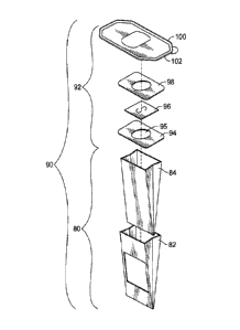
[0054] FIG. 7A is a perspective view of an exemplary filter assembly 90 in
accordance
with the present disclosure. FIG. 7B is a schematic, exploded view thereof.
The filter
assembly 90 comprises a lower bag assembly 80 which includes outer sleeve 82,
and
inner liner 84. The filter structure permits fluid through-flow, such that the
inner liner is
made of a melt-blown material, and the outer sleeve is made of a material such
as
cellulose. The assembly 90 also comprises upper lid assembly 92 that includes
a
rubber or other elastomeric-material diaphragm 96 sandwiched between two
collar
pieces, top and bottom collars 98 and 94 (respectively), each of which have a
central
opening 95 cut therethrough. Collars 94,98 may be made from cellulose or some
other fiberous material. As shown, the top collar 98 is further attached to a
lid 100
having a surrounding rim, or closure, 102, which mates with the upper edge of
vacuum
container 12 in a manner similar to that described above. Some lid assemblies
92
may be simpler. For example, the diaphragm 96 may be incorporated into the lid
100,
as shown in FIG. 7C, or sandwiched between the lid 100 and the bottom collar
94, as
shown in FIG. 7D.
[0055]FIG. 8 illustrates a further embodiment of the present invention, for
use with
reusable filters having an open end to allow for the emptying of collected
debris and
subsequent reuse. Such reusable filter bag assemblies 130, including a filter
bag 132
having an opening 133 in the bottom end, include a filter bag closure clip
160. The
bag closure clip 160 has a hollow, shaped body 162 with opposite, (enlarged)
open
ends 164, 166 and a length "L" that is approximately the same width as the
bottom end
of filter bag 132. It will be appreciated that the length L of the closure
clip 160 can be
varied to accommodate any size and/or type of filter bag. It will also be
appreciated
that while the clip is shown to be generally in the shape of a hollow
cylinder, other
hollow shapes are envisioned, including but not limited to square, triangular,
hexagonal, and octagonal cross-sectional shapes of the clip body 162. In
accordance
with select aspects of the present disclosure, the body 162 of clip 160 has a
length L
12
CA 02859020 2014-08-12
greater than its depth or width. The body of the clip 160 further includes a
slot 168
that extends the entire length L of the body. In accordance with an aspect of
this
embodiment, slot 168 may be provided with a textured or gripping material on
one or
both edges of the slit so as to afford a gripping action on the end of the
filter bag 132
engaged by the clip. Closure clip 160 can further include at least one
orifice, 170, in
the body 162 of the clip, which allows for a consumer to hold the clip 160
while a filter
bag is inserted into the slot 168, without pinching and hindering the clips
action by
compressing the opposite edges of the slot together.
[0056]Closure clip 160 is preferably a rigid object, but in accordance with
select
embodiments it may be flexible or semi-flexible. Clip 160 is preferably
fabricated as a
unitary body of plastic or similar polymeric material by injection molding or
a similar
process. Any plastic or polymeric material that is suitable for the end use of
the
closure clip 160 can be used in the manufacture of the clip.
[0057]FlGs. 9A-9D illustrate the use of such a closure clip 160. In use of
closure clip
160, a consumer opens the bottom end (opposite top end 131 attached to lid
assembly
134) of a full filter bag 132 and discards the contents as appropriate. As
shown in FIG.
9B, the user then compresses the sides of the filter 132 so as to close
opening 133,
and then folds the end of the filter over and upward towards the top of the
filter bag at
least one time, forming a roll, R. As shown in this figure, it is clear that
closure clip 160
is substantially the same length, L, as the width of the filter bag 132. The
consumer
then slides the folded-over end of the filter bag 132 into the clip through
slot 168, in a
direction perpendicular to the bag itself, as illustrated by the arrows (FIG.
9C). During
the step, the consumer may grasp the closure clip 160 via orifice 170 in the
body of
the clip so as to hold the clip in place (without squeezing or pinching it)
while the bag
132 is inserted into the slot 168. As shown in FIG. 9D, upon completing the
insertion
of the closure clip 160 onto the filter bag, the clip acts to keep the end of
the bag
13
CA 02859020 2014-08-12
folded and sealed over in a closed manner, thereby allowing for the economical
reuse
of the filter assembly itself.
[0058] FIG. 11 illustrates a further embodiment of the present invention, for
use with
reusable filters having an open end to allow for the emptying of collected
debris and
subsequent reuse. These reusable filter bag assemblies 230, including a filter
bag
232 having an opening 233 in the top end, include a two-piece lid 234.
Referring also
to FIGS. 12A, 12A, 120, 12D, the lid 234 preferably includes a top piece 234a
and a
bottom piece 234b. The top piece 234a preferably includes the top surface 235
of lid
234 and the opening 240 for fluid communication of the vacuum air carrying
debris into
the filter bag 232. The top piece 234a may also include the diaphragm 96
sandwiched
between one or more collar pieces 98,94 and/or the top surface 235.
[0059] The bottom piece 234b may include the surrounding closure 236
circumscribing
the outer periphery of the bottom piece 234b. The closure 236 also preferably
comprises a radial inner wall 242 and an opposite radial outer wall 244,
together
forming a channel 246 having an inverted U-shape. The outer wall 244 may
further
include an annular, outwardly-directed projection 248. Thus, the bottom piece
234b
may also form the channel 246 to mate with the rim 50 in substantially the
same
manner as described above.
[0060] In any case, the filter bag 232 is secured to the bottom piece 234b by
any of the
methods discussed above, such as adhesive, stitching, and/or thermal welding.
Thus,
the top piece 234a may be removed from the bottom piece 234b to discard the
contents of the bag 232. Then, the top piece 234a may be again mated to the
bottom
piece 234b and the filter bag assembly 230 replaced in the opening 13 of the
housing
12 to continue operation of the vacuum.
14
CA 02859020 2015-12-03
[0061]The top piece 234a preferably mates with and seals to the bottom piece
234b.
Thus, the top piece 234 preferably forms complementary shapes, as shown. For
example, the top piece 234a preferably conforms to portions of the closure
236, such
as portions of the radial inner wall 242.
[0062]The lid 34,134,234 may also include one or more domes 250 that may be
useful
in properly aligning the lid with respect to the housing 12. Referring also to
FIG. 13,
the housing 12 may have complementary shaped protrusions 252 formed therein,
adjacent the opening 13 therein. Referring also to FIG. 14, simpler
filter bag
assemblies 332, having substantially flat lids 334, may simply have cut-outs
350 to
accommodate the protrusions 252, and therefore properly align the lid with
respect to
the housing 12.
[0063] Finally, the housing cap 20 may include an interlock 400, such as that
shown in
U.S. Patent No. 2,742,105 incorporated herein by specific reference, that
prevents the
housing cap 20 from being closed or secured to the housing 12 and/or otherwise
prevents operation of the vacuum when the filter bag assembly is not in place.
For
example, the interlock 400 may include a pivotally mounted arm 402 that
engages the
lid 34,134,234 and thus disengages the interlock, thereby allowing the housing
cap 20
to close securely to the housing 12.
[0064]Other and further embodiments utilizing one or more aspects of the
inventions
described above can be devised without departing from the scope of Applicant's
invention. For example, the shapes of the lid assembly may be specifically
designed
to align with and mate with a specifically shaped filter compartment or
housing for an
upright vacuum. Further, the various methods and embodiments of the methods of
manufacture and assembly of the system, as well as location specifications,
can be
included in combination with each other to produce variations of the disclosed
CA 02859020 2014-08-12
s
methods and embodiments. Discussion of singular elements can include plural
elements and vice-versa.
[0065]The order of steps can occur in a variety of sequences unless otherwise
specifically limited. The various steps described herein can be combined with
other
steps, interlineated with the stated steps, and/or split into multiple steps.
Similarly,
elements have been described functionally and can be embodied as separate
components or can be combined into components having multiple functions.
[0066]The inventions have been described in the context of preferred and other
embodiments and not every embodiment of the invention has been described.
Obvious modifications and alterations to the described embodiments are
available to
those of ordinary skill in the art. The disclosed and undisclosed embodiments
are not
intended to limit or restrict the scope or applicability of the invention
conceived of by
the Applicants, but rather, in conformity with the patent laws, Applicants
intend to fully
protect all such modifications and improvements that come within the scope or
range
of equivalent of the following claims.
16