Note: Descriptions are shown in the official language in which they were submitted.
CA 02859085 2014-06-12
WO 2013/086620 PCT/CA2012/001153
PATIENT SUPPORT OVERLOAD OR OBSTRUCTION DETECTION
FIELD OF THE INVENTION
[0001]
This disclosure relates to patient support devices, such as beds, and more
particularly, to detecting overload or obstruction in patient support
platforms. In
particular, the disclosure relates to the detection of overload or obstruction
of headrests
of beds and the controlling of movement of the headrest in response thereto.
BACKGROUND
[0002]
Patient support devices, such as beds used in hospitals and nursing homes,
are often configurable into different positions. Many of such beds can be
raised and
lowered, as well as have backrests that can be tilted between a prone
(sleeping)
position and a raised (sitting) position. These positions are typically
controlled by one or
more actuators, which are often electrically powered.
[0003]
Backrests or other such moveable platforms can be overloaded or obstructed,
and thus may be prevented from moving as expected. This can cause damage to
the
actuator or other mechanism component. What's more, if the obstruction is
caused by a
person's arm or other body part, injury may result.
SUMMARY OF THE INVENTION
[0004]
A plafform, such as a backrest, of a patient support device, such as a bed, is
controlled in a way that detects and responds to obstruction or overload. To
carry out
this detection, an actuator sensor is referenced when the platform is being
moved in a
first direction (e.g., raised) and a platform sensor is referenced when the
plafform is
being moved in a second direction (e.g., lowered). The actuator sensor can
additionally
be referenced in the second direction. A response to detecting the obstruction
or
- 1 -
CA 02859085 2014-06-12
WO 2013/086620 PCT/CA2012/001153
overload can include one or more of backing off the actuator by a limited
amount and
issuing an alarm.
BRIEF DESCRIPTION OF THE DRAWINGS
[0005] The drawings illustrate, by way of example only, embodiments of
the present
disclosure.
[0006] Fig. 1 is a perspective view of a bed, as an example of a patient
support
device having a moveable platform.
[0007] Fig. 2 is a side view of an actuator assembly of the bed.
[0008] Fig. 3 is a functional block diagram of a controller for the
actuator assembly.
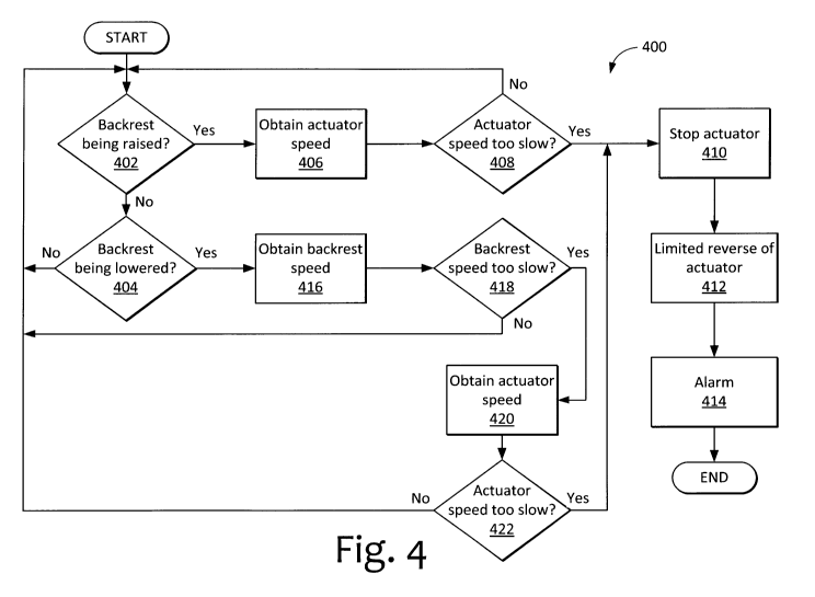
[0009] Fig. 4 is a flowchart of a first example program for the controller.
[0010] Fig. 5 is a flowchart of a second example program for the
controller.
[0011] Fig. 6 is a flowchart of a third example program for the
controller.
DETAILED DESCRIPTION
[0012] A bed is used by way of example to illustrate many of the embodiments
described herein. However, other patient support devices, such as adjustable
chairs,
are also suitable for use with the invention. Moreover, the term "patient" is
not intended
to be limiting, and can be taken to apply to anyone, such as individuals
undergoing
long-term care, hospital patients, and nursing home residents, to name a few.
[0013] Fig. 1 illustrates an example of a bed 100. The bed 100 includes
a
substantially horizontal bed frame 102 with an adjustable mattress support 104
positioned thereon to receive a mattress (not shown) for supporting a person.
In this
embodiment, the mattress support 104 has a backrest 105 or other platform
capable of
moving, and in this case, tilting up and down (raised position shown). At the
head of the
- 2 -
CA 02859085 2014-06-12
WO 2013/086620 PCT/CA2012/001153
bed 100 is a headboard 106, while a footboard 108 is connected to the bed
frame 102
at the foot end of the bed 100. One or more side rails 110 are positioned on
each side
of the bed 100. In this example, two side rails 110 are provided on each side
of the bed
100, making four side rails in total. The two side rails 110 positioned at the
head end of
the bed 100 tilt with the backrest 105. Any of the side rails 110 may be
moveable so as
to facilitate entry and exit of a person.
[0014] The bed 100 includes two leg assemblies 112, 114, each having two
legs
111. The head leg assembly 112 is connected at the head of the bed 100 and the
foot
leg assembly 114 is connected at the foot of the bed 100. Upper portions of
the legs
111 of the leg assemblies 112, 114 are connected to one or more linear
actuators (not
shown) that can move the upper portions of the legs 111 back and forth along
the length
of the bed 100. Leg braces 116 pivotably connected to the legs 111 and to the
bed
frame 102 constrain the actuator movement applied to the legs 111 to move the
leg
assemblies 112, 114 in a manner that raises and lowers the bed frame 102. In
other
words, the leg assemblies 112, 114 are linkages that collapse and expand to
respectively lower and raise the bed frame 102. The lower ends of the leg
assemblies
112, 114 are connected to caster assemblies 118 that allow the bed 100 to be
wheeled
to different locations.
[0015] The bed 100 further includes an attendant's control panel (not
shown) at the
footboard 108 that can, among other things, control the height of the bed
frame 102
above the floor, as well as the tilt of the backrest 105 of the mattress
support 104. The
bed 100 further includes a controllable knee-height adjustment mechanism 120
to move
one or more lower-body support platforms 121. To allow for similar adjustment,
an
occupant's control panel (not shown) can be provided, for example, on a side
rail 110.
- 3 -
CA 02859085 2014-06-12
WO 2013/086620 PCT/CA2012/001153
[0016] It should be emphasized that the bed 100 is merely one example of
a bed or
other patient support that may be used with the obstruction or overload
detection and/or
actuator control techniques' described herein. Other examples of beds that can
be used
include ultra-low type height-adjustable beds such as those disclosed in US
Patent
Publication No. 2011/113556 and US Patent No. 7,003,828, the entirety of both
documents being incorporated herein by reference.
[0017] As mentioned, the backrest 105 of the mattress support 104 is
variably
positionable, and accordingly can be raised and lowered so that the occupant
of the bed
100 can be provided with, for example, a range of positions between fully
prone and
sitting upright. A backrest support 122 is pivotably connected to the bed
frame 102 and
supports the backrest 105 over its range of positions.
[0018] A backrest actuator assembly 124 is connected between the backrest 105
and the bed frame 102 and is configured to raise and lower the backrest 105
with
respect to the bed frame 102. In this example, the backrest actuator assembly
124
includes a backrest actuator 128 that is connected to the bed frame 102. The
backrest
actuator assembly 124 further includes a damper 130 that is connected in
series with
the actuator 128 at one end, and that is pivotably connected to a lever arm
126
extending from the backrest support 122 at another end. The lever arm 126 may
also be
known as a head gatch bracket.
of actuator, such as a hydraulic cylinder.
[0020] The damper 130 can be a fluid-filled damper, such as a hydraulic
damper,
gas spring, or the like. The damper 130 is configured to provide damping over
a range
- 4 -
CA 02859085 2014-06-12
WO 2013/086620 PCT/CA2012/001153
of motion. For the linear style damper described herein, range of motion may
be known
as damper stroke. Generally, dampers may also be known as dampeners or
dashpots.
[0021] The damper 130 can be a lockable damper that is configured to
rigidly or
nearly rigidly lock at any position on the range of motion. In one embodiment,
the
lockable damper 130 includes a cylindrical body through which a piston slides.
Each
side of the piston has a chamber of fluid that is selectively communicated by
actuating
an unlocking pin that opens a valve in the piston to allow fluid to move
between the
chambers. Relative movement between the cylindrical body and a rod extending
from
the piston can then be damped (valve open) or held rigid (valve closed). In
another
embodiment, the damper 130 is locked by a separate external locking mechanism.
In
yet another embodiment, other kinds of dampers can be used. The damper 130 can
be,
for example, a BLOC-0-LIFTTm device sold by Stabilus GmbH of Koblenz, Germany.
[0022] During normal operation of the bed 100, the damper 130 is locked
in an
extended state and movement of the actuator 128 causes the damper 130 to push
or
pull against the lever arm 126 to raise or lower (arrow R) the backrest 105 as
commanded by the controller operated by the bed's occupant or an attendant,
such as a
nurse or caregiver.
[0023] The backrest actuator assembly 124 can further include a
mechanical
release, which can include a manually actuated handle, connected to the damper
130.
Components of the release may also be provided in the damper 130. The release
may
be known as a cardiopulmonary resuscitation (CPR) quick release. The release
is
configured to unlock the lockable damper 130 when actuated to an unlocked
position,
thereby allowing the damper 130 to contract without the actuator 128 having to
be
operated. During an emergency, such as a cardiac arrest of the bed's occupant,
the
release can be manually actuated to quickly allow the backrest 105 to lower
due to
- 5 -
CA 02859085 2014-06-12
WO 2013/086620 PCT/CA2012/001153
gravity as shown by arrow E (lowered position shown in phantom line). The rate
of
lowering of the backrest 105 is controlled at least in part by the damping
effect of the
damper 130 as it contracts over its damped range of motion under the weight of
the
backrest 105, backrest support 122, attached side rails 110, mattress, the
occupant's
upper body, and any other items in or on the backrest 105.
[0024] After the CPR release has been actuated and while the backrest 105 is
lowering due to gravity, the release can be manually returned to its original
position, or
lock position, to lock the lockable damper 130 at its current length and
thereby stop the
lowering of the backrest 105. The backrest 105 can be stopped at any position
along
the damped range of motion, which can make for safer bed operation. For
example, if
the arm of the occupant or that of a person standing near the bed becomes
caught
under the backrest 105 during a CPR release, the backrest 105 can be
temporarily
stopped to reduce the chance of injury.
[0025] Fig. 2 shows a side-view diagram of the actuator assembly 124.
The actuator
assembly 124 connects a portion 202 of the bed frame 102 to the lever arm 126
that
extends downward from the backrest support 122 opposite a pivot connection 204
to
another portion 206 of the bed frame. As the actuator assembly 124 extends and
retracts parallel to arrow D, the backrest support 122 rotates as indicated by
arrow R.
[0026] The actuator assembly 124 includes the actuator 128 and the damper 130
connected in series with the actuator 128. Accordingly, the damper 130 is
loaded in
compression by the actuator 128 when the backrest support 122 is being raised
to raise
the backrest 105. The damper 130 is pulled by the actuator 128 when the
backrest
support 122 is being lowered to lower the backrest 105; however, the weight of
the
backrest support 122 and load that it carries generally keeps the damper 130
in
compression.
- 6 -
CA 02859085 2014-06-12
WO 2013/086620 PCT/CA2012/001153
[0027] The actuator 128 includes a housing 208 that is pin connected at
210 to the
portion 202 of the bed frame. A connector block 212 connects an extendable and
retractable rod 214 of the actuator 128 to the damper 130.
[0028] The damper 130 includes a cylinder 216 and an extendable and
retractable
rod 218 connected between the connector block 212 and a bearing block 220,
which is
pin connected at 222 to the lever arm 126 of the patient support device.
[0029] In this example, the damper 130 is a lockable damper, as
described above.
The damper 130 is normally locked rigid in an extended state. A release 224
includes a
pull-cable 226 connected at one end to a manually operated handle 228 that is
located
on the bed. The other end of the pull cable 226 is connected to a damper
release
mechanism at the bearing block 220. Such a release mechanism can include a
lever
that interacts with an unlocking pin of the damper 130. Actuation of the
handle 228 thus
frees the damper 130 to extend or retract, and thus allows damped relative
movement
of the bearing block 220 with respect to the connector block 212.
[0030] The damper 130 is locked during normal raising and lowering of the
lever arm
126. Moreover, the damper 130 provides damping over its range of motion when
unlocked during, for example, an emergency lowering of the backrest support
122. After
the damper 130 is compressed after an emergency lowering of the backrest
support,
the damper release mechanism can again be actuated to unlock the damper 130,
and
at the same time, the actuator 128 can be retracted to extend the damper to
its normal
operational length before the damper 130 is locked again.
[0031] Obstruction or overload detection techniques will now be
described in the
context of the above-described actuator assembly 124 having the actuator 128
in series
with the damper 130. These obstruction or overload detection techniques may
comprise
- 7 -
CA 02859085 2014-06-12
WO 2013/086620 PCT/CA2012/001153
actuator control techniques. It should be understood that these techniques can
be used
with other actuator assemblies, other beds, and other patient support
platforms.
[0032] As shown in Fig. 2, an actuator sensor 230, a backrest sensor
232, and
optionally at least one load sensor 234 are provided.
[0033] The actuator sensor 230 is configured to sense movement of the actuator
128. In this embodiment, the actuator sensor 230 is a rotary encoder located
inside the
housing 208 of the actuator 128. The actuator sensor 230 senses movement of a
drive
component, such as a rotating gear, of the actuator 128 and outputs a signal
having
pulses, where each pulse indicates a linear relative displacement of the
actuator rod
214 with respect to the housing 208. In other embodiments, the actuator sensor
230 can
be located elsewhere and can include other types of sensors such as one or
more
suitably positioned Reed switches or Hall effect sensors, an accelerometer, or
the like.
[0034] The backrest sensor 232 is configured to sense movement of the backrest
105. In this embodiment, the backrest sensor 232 is an accelerometer attached
to the
backrest support 122. Accordingly, the backrest sensor 232 can output a signal
indicative of an acceleration of the backrest 105, and such signal can be
integrated to
obtain a rate or speed of movement of the backrest 105 and integrated again to
obtain a
displacement of the backrest 105. In other embodiments, the backrest sensor
232 can
be located elsewhere and can include other types of sensors such as an
inclinometer,
one or more suitably positioned Reed switches or Hall effect sensors, a rotary
encoder,
or the like.
[0035] The load sensor 234 is positioned to sense a load at the backrest
105. In this
embodiment, two load sensors 234 are positioned at the head of the bed between
the
upper portion 206 of the bed frame and a lower frame portion 236 that connects
to the
- 8 -
CA 02859085 2014-06-12
WO 2013/086620 PCT/CA2012/001153
leg assemblies 112, 114. The two load sensors 234 are located at opposite
sides of the
bed and may be designated head-left and head-right load sensors. The load
sensors
234 can provide for measurement of the weight in the bed in conjunction with
two
similar load sensors positioned at foot-left and foot-right positions.
Although the load
sensed by the load sensors 234 may not be directly proportional to the weight
on the
backrest 105, the load sensors 234 output signals indicative of the weight on
the
backrest 105, such that the weight on the backrest 105 can be readily obtained
by
performing a calculation. In this example, the load sensors 234 are bending
beam load
cells. In other examples, the load sensor 234 can include other types of
sensors. Other
positions are also contemplated for the load sensor 234, such as between the
backrest
support 122 and the mattress. The load sensors 234 may be used in conjunction
with
one or both of the actuator sensor 230 or the backrest sensor 232 to provide
redundant
or alternative modes of detecting obstruction or overload.
[0036] Fig. 3 shows a controller 300. The controller 300 includes a
processor 302
connected to a user interface 304, a memory 306, and an analog-to-digital
converter
308 for the backrest sensor 232 and load sensor 234. The analog-to-digital
converter
308 can be omitted if the outputs of the backrest sensor 232 and load sensor
234 are
digital. Signals between the processor 302 and the actuator 128 and actuator
sensor
230 can be routed through the analog-to-digital converter 308 if these signals
are
analog.
[0037] The processor 302 can be a microcontroller of the kind that is
readily
commercially available for controlling actuators and auxiliary devices.
[0038] The user interface 304 can include buttons and a screen for
controlling
operation of the bed 100. For example, buttons can be provided to command the
- 9 -
CA 02859085 2014-06-12
WO 2013/086620 PCT/CA2012/001153
actuator 128 to raise and lower the backrest 105. Such buttons can include
momentary
contact switches, which may also be known as "hold-and-run" switches.
[0039] The memory 306 can be a random-access memory (RAM), a read-only
memory (ROM), or the like. The memory 306 can store an actuator program 310
that
includes instructions executable by the processor 302 for controlling the
actuator 128
during normal operation. Specifically, the actuator program 310 includes
instructions
that generate control signals for the actuator 128 in response to commands
received
from the user interface 304. That is, the program 310 causes the processor 302
to
output a backrest raising signal to the actuator 128 in response to receiving
a backrest
raising command at the user interface 304, and output a backrest lowering
signal to the
actuator 128 in response to receiving a backrest lowering command at the user
interface 304. The actuator program 310 may further include maximum and
minimum
allowable extents of movement of the actuator 128, so that a commanded raising
movement of the backrest 105 can be prevented when the backrest 105 is fully
raised
and a commanded lowering movement of the backrest 105 can be prevented when
the
backrest 105 is fully lowered. The actuator program 310 further includes
instructions to
stop actuation of the backrest 105 under certain conditions.
[0040] Specifically, in a first example, the program 310 configures the
controller 300
to stop the backrest actuator 128 from raising the backrest 105 in response to
a
characteristic signal from the actuator sensor 230, and further, to stop the
backrest
actuator 128 from lowering the backrest 105 in response to characteristic
signals from
both the actuator sensor 230 and the backrest sensor 232. Stopping the
backrest 105 in
this way can prevent damage to the actuator 128 or injury to a person should
the
backrest 105 become obstructed or overloaded.
- 10 -
CA 02859085 2014-06-12
WO 2013/086620 PCT/CA2012/001153
[0041] The program 310 includes instructions that interpret the
characteristic signal
from the actuator sensor 230 as being indicative of a rate of movement of the
actuator
128 being lower (i.e., slower) than an expected rate of movement of the
actuator 128.
Since, in this example, the actuator sensor 230 is a rotary encoder, the
characteristic
signal from the actuator sensor 230 has a pulse rate lower than an expected
pulse rate.
Suppose, for example, that when the actuator 128 is extended or retracted the
actuator
sensor 230 is normally expected to output 500 pulses (+/- 5 pulses) per
second, which
corresponds to a 1 inch (25 mm) per second extension or retraction of the
actuator 128.
The program 310 accordingly stores one or more expected pulse rates that are
less
than 495 pulses (500 - 5) per second. The characteristic signal from the
actuator sensor
230 is then an actual pulse rate of less than 495 pulses per second, which
indicates that
something may be preventing the backrest 105 from moving normally in response
to
actuation by the actuator 128.
[0042] The program 310 further includes instructions that interpret the
characteristic
signal from the backrest sensor 230 as being indicative of a rate of lowering
of the
backrest 105 being lower (i.e., slower) than an expected rate of lowering. In
this
example, the backrest sensor 230 is an accelerometer that provides
acceleration
signals to the processor 302. The program 310 integrates the accelerations to
obtain
velocities that are then further processed by the program 310, taking into
account the
location of the backrest sensor 230, to obtain at least an angular speed of
the backrest
105. Continuing the above numerical example, suppose that the 1 inch (25 mm)
per
second normal rate of extension or retraction of the actuator 128 corresponds
to a 1
degree per second normal angular speed of raising or lowering the backrest
105. The
program 310 accordingly stores an expected angular rate of lowering of the
backrest of
0.95 degrees per second (5% being allocated for sensor error or other
consideration).
- 11 -
CA 02859085 2014-06-12
WO 2013/086620 PCT/CA2012/001153
The characteristic signal from the backrest sensor 230 is then a signal that
corresponds
to 0.95 degrees per second or slower, which indicates that something may be
preventing the backrest 105 from moving normally in response to actuation by
the
actuator 128.
[0043] The characteristic signals from the actuator sensor 230 and the
backrest
sensor 230 are referenced as follows to stop the backrest in case of
obstruction or
overload.
[0044] When the backrest 105 is being raised, the program 310 references
a stored
expected actuator pulse rate for raising. The program 310 monitors the
measured or
actual pulse rate from the actuator sensor 230, compares the actual pulse rate
with the
expected pulse rate for raising, and then stops the actuator 128 when the
actual pulse
rate is lower than the expected pulse rate for raising. Continuing the
numerical example,
the stored expected pulse rate for raising can be 490 pulses per second, which
allows
for a small reduction in backrest raising rate that may be due to, for
example, a heavier
than usual occupant shifting his/her weight.
[0045] When the backrest is being lowered, the program 310 references
the stored
expected angular rate of lowering of the backrest 105, discussed above, and
further
references a stored expected actuator pulse rate for lowering of the backrest
105. The
program 310 monitors the measured or actual angular rate of lowering of the
backrest
105 computed based on the backrest sensor 232 and monitors the measured or
actual
pulse rate from the actuator sensor 230. The program 310 compares the actual
angular
rate with the expected angular rate of lowering and compares the actual pulse
rate with
the expected pulse rate for lowering. The program 310 stops the actuator 128
when the
actual angular rate is lower than the expected angular rate of lowering and/or
the actual
pulse rate is lower than the expected pulse rate for lowering. Continuing the
numerical
- 12 -
CA 02859085 2014-06-12
WO 2013/086620 PCT/CA2012/001153
example, the stored expected angular rate of lowering is 0.95 degrees per
second and
the stored expected pulse rate for lowering can be 495 pulses per second. In
this
example, the stored expected pulse rate for lowering is higher than the stored
expected
pulse rate for raising. Thus, when the actuator sensor 230 outputs a pulse
rate of lower
than 495 pulses per second and/or the backrest sensor 232 outputs a signal
that
corresponds to an actual angular rate of less than 0.95 degrees per second,
then the
actuator 128 is stopped.
[0046] In this example, only the actuator sensor 230 is referenced
during backrest
raising as it is expected that the actuator sensor 230 will respond rapidly to
obstructions
and before damage to the actuator 128 can occur. On the other hand, the
backrest
sensor 232 is used in conjunction with the actuator sensor 230 during lowering
of the
backrest 105 because the actuator 128 may continue to move after the lowering
backrest is obstructed due to mechanical play (i.e., looseness) in the
actuator assembly
124, such as a tendency for the damper 130 to more readily extend than
contract or
play in the damper release mechanism. Pin connections may also have play that
may
contribute to an overall mechanical hysteresis that may be exhibited when the
backrest
105 is obstructed from lowering while the actuator 128 is retracting.
Therefore, the pulse
rate of the actuator sensor 230 may not decrease rapidly enough to stop the
actuator
128 in time to prevent damage or injury. Accordingly, the backrest sensor 232
is also
referenced during lowering as a way of correlating a slight decrease in the
pulse rate of
the actuator sensor 230 with an immobile backrest 105. However, both the
actuator
sensor 230 and the backrest sensor 232 can be used during raising in the same
manner
as described for lowering to provide additional flexibility or redundancy when
detecting
the presence of an obstruction or overload condition. The characteristic
signals of both
the backrest sensor 232 and the actuator sensor 230 can be used together to
increase
- 13 -
CA 02859085 2014-06-12
WO 2013/086620 PCT/CA2012/001153
the accuracy and speed of determination of an obstruction being present. The
characteristic signals of the actuator sensor 230 and the backrest sensor 232
that
indicate the need to stop the backrest actuator 128 need not be constant. For
example,
each of the expected pulse rate for lowering the backrest 105, the expected
pulse rate
for raising the backrest 105, and the expected angular rate of lowering the
backrest 105
can vary with respect to backrest position or load, as measured by load sensor
234.
One or more formulas or lookup tables can be referenced by the program 310 to
establish each of these expected values based on backrest position or load.
For
example, the backrest 105 may move faster when higher and may move slower when
lower, and the characteristic signals can be defined to accommodate for this.
[0047] After the backrest 105 has been stopped, additional safeguards may be
taken.
[0048] The program 310 can further configure the controller 300 to command a
limited reverse movement from the actuator 128 in response to at least one of
the
characteristic signals. That is, after the actuator 128 is stopped in response
to an
obstruction, the actuator 128 can be backed-off by a small amount to release
stress/strain from the actuator assembly 124 and reduce any pinching of the
backrest
105 or related structure on the obstruction. In this example, the limited
reverse
movement of the actuator 128 is accomplished by reversing the actuator
direction for
about half a second.. The program 310 can further configure the controller 300
to
generate an alarm signal in response to at least one of the characteristic
signals. The
alarm signal can be issued to an alarm device, such as a speaker, light, or
similar
device, to output an audible or visual alert to warn the operator of the bed
of the
detection of an obstruction or overload condition.
- 14 -
CA 02859085 2014-06-12
WO 2013/086620 PCT/CA2012/001153
[0049] Referring to the flowchart of Fig. 4, a method 400 can be used as
a basis for
the program 310 in the first example described above.
[0050] At 402 and 404 it is determined whether a command is being issued to
extend
or retract the actuator 128, for example to result in raising or lowering of
the backrest
105. If the controller 300 is not commanding movement of the backrest 105, for
example
no one is pressing and holding the up or down button on the user interface
304, then
the remainder of the method 400 need not be performed until such a command
occurs.
The check performed at 402 and 404 can be periodically made at a rate of, for
example,
several times a second.
[0051] Once it has been determined that a command to raise the backrest 105
has
been received, at 406, the speed of the actuator 128 is sensed. This can be
performed
by the actuator sensor 230, such as the rotary encoder, as discussed above.
During this
time, the actuator 128 extends. Step 406 can be combined with step 402, as
sensing
actuator speed is one way of determining that the backrest is being raised.
[0052] At 408, the measured or actual speed of the actuator 128 is compared
with an
expected speed of the actuator 128. The expected speed of the actuator 128 can
be a
constant or can be variable with respect to the position of the backrest 105
or load on
the backrest 105, as discussed above. If the actual speed is not too slow, no
action
need be taken and the method 400 returns to the start. If the actual speed is
detected to
be too slow, it is determined that the backrest 105 is in an obstructed or
overloaded
condition, and accordingly the actuator 128 is stopped, at 410.
[0053] Also in response to the obstructed or overloaded condition, at
412, the
actuator 128 can then be automatically reversed by a limited amount or for a
limited
- 15 -
CA 02859085 2014-06-12
WO 2013/086620 PCT/CA2012/001153
time to relieve stress/strain or free the obstruction. At about the same time,
an alarm
can be issued to alert the operator to the problem, at 414.
[0054] On the other hand, if it has been determined that a command to
retract the
actuator and/or lower the backrest 105 has been issued, at 416, the speed of
the
backrest 105 is determined. This can be performed by the backrest sensor 232,
such as
the accelerometer, as discussed above, and may involve computing a velocity
from a
sensed acceleration. During this time, the actuator 128 retracts and
accordingly lowers
the backrest 105. Step 416 can be combined with step 404, as sensing the
backrest
speed is one way of determining that the backrest is being lowered.
[0055] At 418, the speed of the backrest 105 is compared with an expected
speed of
the backrest 105. The expected speed of the backrest 105 can be a constant or
can be
variable with respect to the position of the backrest 105 or load on the
backrest 105, as
discussed above. If the backrest speed is not too slow, no action need be
taken and the
method 400 returns to the start. If the expected speed is detected to be too
slow, it is
determined that the backrest 105 may be in an obstructed or overloaded
condition, and
accordingly the actuator 128 speed is obtained and compared to an expected
speed of
the actuator 128, at 420 and 422. For steps 420 and 422, the description above
for
steps 406 and 408 can be referenced, however, the expected speed for lowering,
used
at 422, can be different from the expected speed for raising, used at 408.
[0056] If it is determined at 422 that the actual speed of the actuator is
too slow, then
it is determined that the backrest 105 is in an obstructed or overloaded
condition, and
accordingly the actuator 128 is stopped, at 410. The actuator 128 can then be
automatically reversed by a limited amount or for a limited time to relieve
stress/strain or
free the obstruction, at 412, and the alarm can be issued tto alert the
operator to the
problem, at 414.
- 16 -
CA 02859085 2014-06-12
WO 2013/086620 PCT/CA2012/001153
[0057] The steps of the method 400 can be performed in orders different from
those
described above. For example, the positions of steps 416 and 418 can be
swapped with
the positions of steps 420 and 422, such that the actuator speed is evaluated
before the
backrest speed. Moreover, the raising/lowering determination at 402 and 404
can be
made after or while the actuator speed is obtained.
[0058] In other examples, the stored expected pulse rate for lowering
can be
selected to be equal to or greater than that for raising. In still other
examples, the
program 310 uses the backrest sensor 232 as the condition for detecting an
obstruction
at the backrest 105 during lowering unless the output of the backrest sensor
232 is
erroneous, too noisy, or otherwise corrupt, in which case the program 310 uses
the
actuator sensor 230 as the condition for detecting an obstruction at the
backrest 105. In
still other examples, the program 310 references only the backrest sensor 232
as the
condition for detecting an obstruction at the backrest 105 during lowering.
Some of
these examples will now be discussed below.
[0059] Referring to the flowchart of Fig. 5, a method 500 can be used as a
basis for
a second example of the program 310. Most steps of the method 500 are the same
as
the method 400, and the above description can be referenced for steps with
like
reference numerals.
[0060] When the backrest is being lowered at 404, a signal from the
backrest sensor
232 is assessed to determine whether the signal is acceptable, at 502. Reasons
that the
signal may be unacceptable include, but are not limited to, the following: the
backrest
sensor 232 has failed, the signal is too noisy, the signal is outside a
predetermined
acceptable range (i.e., the signal is erroneous), or the signal is delayed. If
the signal is
unacceptable, then only the actuator speed is used to control stopping of the
backrest
105 in case of obstruction or overload, and the method progresses to 406. Step
406 can
- 17 -
CA 02859085 2014-06-12
WO 2013/086620 PCT/CA2012/001153
reference the same expected actuator speed as when raising the backrest 105 or
a
different expected actuator speed, as triggered by the arrival at step 406
from step 502.
If the backrest sensor 232 signal is acceptable, then step 416 is performed
and only the
backrest speed is used to control stopping of the backrest 105 in case of
obstruction or
overload.
[0061] The method 500 for the second example of the program 310 thus relies on
the backrest sensor 232 during lowering if its output is acceptable, and
otherwise
reverts to using the actuator sensor 230.
[0062] Referring to the flowchart of Fig. 6, a method 600 can be used as
a basis for
a third example of the program 310. Most steps of the method 600 are the same
as the
method 400, and the above description can be referenced for items with like
reference
numerals.
[0063] The method 600 relies on only the backrest sensor 232 to stop the
lowering of
the backrest 105 in case of obstruction or overload. That is, at 418, if
referencing the
backrest sensor 232 determines that the backrest 105 speed is too slow, the
actuator is
immediately stopped at 410 without referencing the actuator sensor 230. In
this
example, the backrest sensor 232 is sensitive or reliable enough to be relied
on for
detecting obstruction or overload during lowering of the backrest 105.
[0064] In the above, speed or rate of actuator or platform (backrest)
movement is
used to determined when to stop movement of the platform (backrest) in case of
obstruction or overload of the platform (backrest). In other examples,
displacement can
be used instead of speed.
[0065] Persons of skill in the art will readily understand that the
techniques described
herein for detecting obstruction or overload and/or controlling movement are
applicable
- 18 -
CA 02859085 2014-06-12
WO 2013/086620 PCT/CA2012/001153
to other elements of the patient support other than the backrest. For example,
actuators
for height adjustment of the patient support plafform, knee or foot
height/angle
adjustment, platform width, etc., may all use embodiments of the techniques
described
herein to similar effect. In addition, various combinations of the sensors
described
herein may be used to provide redundancy or increased speed/accuracy of
obstruction
detection, depending on the expected obstruction modes for the actuator to
which they
are applied. Various alarm modes may be implemented in conjunction with
obstruction
detection. "Obstruction" is meant to include interference between any portion
of the
patient support or platform and any person or thing that might impede or tend
to impede
motion of the patient support or plafform. This includes interference between
the
platform (and/or accessories of the bed attached to the platform, such as the
siderails)
and people, walls, floors, furniture and/or, ancillary equipment in the room.
"Overload
condition" is meant to include conditions whereby allowable load limits are
exceeded,
irrespective of the presence of obstructions, on components of the patient
support or
plafform. "Actuator sensor" is meant to include all types of linear position
sensors,
whether internal or external to the actuator. "Backrest sensor" is meant to
include all
types of movement based sensors, whether located on the backrest or another
part of
the patient support or platform. The movement based sensors may include
sensors that
measure angular movement or acceleration. "Load sensor" is meant to include
sensors
that measure strain or deflection. Other types of sensors not explicitly
described herein
that produce similar effects suitable for use with the present invention are
known to
those skilled in the art.
[0066] While the foregoing provides certain non-limiting example
embodiments, it
should be understood that combinations, subsets, and variations of the
foregoing are
contemplated. The monopoly sought is defined by the claims.
- 19 -