Note: Descriptions are shown in the official language in which they were submitted.
CA 02859532 2014-08-15
SLIDING SHOWER DOOR GUIDE AND DRAIN ASSEMBLY
TECHNICAL FIELD
[0001] Various embodiments relate to a guide system for a sliding door,
such as a shower
door assembly.
BACKGROUND
[0002] Shower enclosures often have glass doors that slide to enclose the
bathing area and
keep liquid water and/or steam in the bathing area. The shower enclosures may
also have a separate
continuous drain system adjacent to the entrance to the shower enclosure to
drain liquid water from
the shower enclosure.
SUMMARY
[0003] According to an embodiment, a guide assembly is provided with a
drain channel
having a base wall and first and second side walls extending along a
longitudinal axis. A cover
extends over the channel. The cover has a first guide channel and a second
guide channel extending
longitudinally and spaced apart by an intermediate member. The first guide
channel is sized to
receive an edge portion of a first sliding door of a shower door assembly. The
second guide channel
is sized to receive an edge portion of a second sliding door of the shower
door assembly. A base
section of the first channel defines a first series of apertures providing
fluid communication between
the first channel and the drain channel. A base section of the second channel
defines a second series
of apertures providing fluid communication between the second channel and the
drain channel.
[0004] According to another embodiment, a guide and drain assembly for
sliding doors is
provided. A drain channel has a base wall and first and second side walls
extending along a
longitudinal axis. A cover extends over the channel. The cover has a first
guide channel formed by
a first base section positioned between first and second sides, and a second
guide channel formed by
a second base section positioned between third and fourth sides. The first and
second guide channels
extend longitudinally and are spaced apart by an intermediate member. A first
edge member extends
CA 02859532 2014-08-15
outwardly from the first guide channel, and a second edge member extends
outwardly from the
second guide channel. The first guide channel is sized to receive an edge
portion of a first sliding
door of a shower door assembly. The second guide channel is sized to receive
an edge portion of a
second sliding door of the shower door assembly. A base section of the first
channel defines a first
series of apertures extending longitudinally in the first channel and
providing fluid communication
between the first channel and the drain channel. A base section of the second
channel defines a
second series of apertures extending longitudinally in the first channel and
providing fluid
communication between the second channel and the drain channel. The
intermediate member of the
cover defines a third series of apertures extending longitudinally and in
fluid communication with
the drain channel.
[0005] According to yet another embodiment, a guide and drain assembly is
provided. A
drain channel has a base wall and first and second side walls extending along
a longitudinal axis. A
cover extends over the channel. The cover has at least one guide channel
extending along the
longitudinal axis and positioned between first and second edge members. The at
least one guide
channel is formed by a first base section positioned between first and second
sides. The at least one
guide channel is sized to receive an edge portion of a sliding door of a
shower door assembly. The
base section of the at least one guide channel defines a series of apertures
extending longitudinally
and providing fluid communication between the guide channel and the drain
channel.
[0006] Various embodiments of the present disclosure have associated, non-
limiting
advantages. For example, the guide and drain assembly provides a single
component for placement
at the entry to a shower enclosure. The assembly provides a drainage function
for the shower, which
is partially hidden by the sliding shower doors, where liquid water flows
through a cover and into a
drainage channel. The cover includes guide channels that act as guides for the
sliding doors to keep
the sliding doors translating in a single plane of motion and prevent the
doors from moving
perpendicularly to the longitudinal sliding plane or direction
BRIEF DESCRIPTION OF THE DRAWINGS
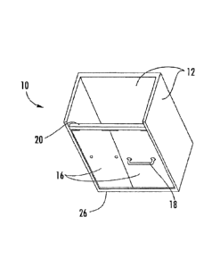
[0007] FIGURE 1 is a perspective view of a shower assembly having sliding
doors according
to an embodiment;
2
CA 02859532 2014-08-15
[0008] FIGURE 2 is a front perspective view of the shower assembly of
Figure 1;
[0009] FIGURE 3 is a top perspective view of the shower assembly of Figure
1;
[0010] FIGURE 4 is a sectional view of the shower assembly of Figure 1;
[0011] FIGURE 5 is a detailed view of a guide and drain assembly in the
shower assembly of
Figure 4 according to an embodiment; and
[0012] FIGURE 6 is a top perspective view of a cover for use with the guide
and drain
assembly of Figure 5.
DETAILED DESCRIPTION
[0013] As required, detailed embodiments of the present invention are
disclosed herein;
however, it is to be understood that the disclosed embodiments are merely
exemplary of the
invention that may be embodied in various and alternative forms. The figures
are not necessarily to
scale; some features may be exaggerated or minimized to show details of
particular components.
Therefore, specific structural and functional details disclosed herein are not
to be interpreted as
limiting, but merely as a representative basis for teaching one skilled in the
art to variously employ
the present invention.
[0014] Figures 1-4 illustrate a shower enclosure 10 according to an
embodiment. The
shower enclosure 10 has one or more walls 12, and a floor 13. A shower head,
valves to control the
flow and temperature of water to the shower head may be provided within the
enclosure 10.
[0015] The walls 12 and the threshold 14 cooperate to provide an opening or
doorway to the
shower enclosure 10 for gaining access to or leaving the shower enclosure 10.
The opening may be
covered by one or more sliding doors 16. In other embodiments, the doors 16
may be pivotally
mounted to the shower enclosure 10.
[0016] The sliding doors 16 may be framed or frameless glass panels, may be
made from a
plastic panel, or from another material as is known in the art. The doors 16
may be one or more
towel bars or handles 18 mounted to the door.
3
CA 02859532 2014-08-15
[0017] The sliding doors 16 are hung on an upper track 20. The upper track
20 may be
mounted to two opposed side walls 12 or a ceiling or top wall (not shown). The
sliding doors 16
have a mechanism (not shown) such as a roller system or the like, that allows
the sliding doors to
move along a longitudinal axis 22. The upper track 20 may have a pair of guide
rails, one for each
mechanism on each door 16 such that the doors are offset from one another
along a transverse or
lateral axis 24. This also allows one door to slide behind the other door, and
vice versa, to open and
close the opening to the enclosure 10. In other embodiments, a single sliding
door may be provided,
that slides over an adjacent wall section when open, for example, one of the
door panels as shown
may be fixed in place while the other is movable
[0018] A integrated drain and guide system or assembly 26 that guides the
sliding doors 16
and provides a drain is provided at the threshold of the opening to the shower
enclosure 10. The
assembly 26 replaces a conventional bottom track and separate drain system
near the threshold.
[0019] Generally, sliding shower doors are provided with a guiding system
to keep the doors
tracking along their intended plane of travel as they move. In conventional
systems, the guiding
system may include a bottom track attached to the threshold of the shower
enclosure that has
hardware such as flanges or the like to restrict the movement of the doors
perpendicular to the plane
of travel, or in the lateral direction 24. The conventional bottom track and
associated hardware may
be visually unappealing, and may provide a place for dirt and/or grime to
accumulate. Conventional
shower enclosures may also be provided with a continuous drain system located
at the entrance to
the bathing area, or near the threshold, and spaced apart from the bottom
track. These drains are
often rectangular in shape and covered by a grate, such as a metal grate that
is perforated to allow
water to enter the drain system and leave the shower enclosure.
[0020] The assembly 26 of the present disclosure replaces both the
conventional bottom
guide track and continuous drain system. The assembly 26 is formed such that
it functions both as a
drain grate, and as a guiding mechanism for the shower doors 16. The assembly
26 also eliminates
the need for a bottom track for the shower door assembly. The assembly 26 may
provide an
improved visual appearance for the shower door assembly, as the drain system
is less visible, and the
bottom track may protrude less into the opening to the shower enclosure.
4
CA 02859532 2014-08-15
[0021] Figure 5 illustrates the assembly 26 in greater detail and is a view
taken along the
longitudinal axis of the assembly. Figure 6 illustrates a top view
illustrating a cover member for the
assembly 26. assembly may extend the length of the opening to the shower
enclosure, for example,
from wall 12 to wall 12 as shown in Figure 2.
[0022] The assembly 26 has a drain channel 28. The drain channel 28 has a
base wall 30 and
first and second side walls 32, 34 extending along the longitudinal axis 22.
The drain channel 28
may have a generally rectangular cross section, as shown. The drain channel 28
may define an
aperture to connect to a fitting to a drain pipe (not shown). The base wall 30
of the drain channel
may be inclined or sloped towards the aperture to drain water, and the
aperture may be located
adjacent to one of the ends of the channel. The drain channel 28 may have a
pair of end walls 36 at
opposed ends of the channel 28.
[0023] The assembly 26 also has a cover member, or cover, 38. The cover 38
extends over
the drain channel 28 to cover the drain channel, and has a length
approximately equal to or greater
than the length of the drain channel 28, and a width that is approximately
equal to or greater than the
width of the drain channel 28. The drain channel 28 and the cover 38 may be
made from a metal
such as aluminum or an aluminum alloy, or may be made from another suitable
material.
[0024] The cover 38 has at least one guide channel, with one guide channel
provided per
sliding door. The cover 38 as shown has a first guide channel 40 and a second
guide channel 42.
The guide channels 40, 42 extend longitudinally and may be generally parallel
to one another.
[0025] The first guide channel 40 is sized to receive an edge portion 44 of
a first sliding door
16 of a shower door assembly. The edge portion 44 may be a frameless glass
panel as shown, or
may be a guide from a frame surrounding a panel. The first guide channel 40
has a base section 46
and first and second side portions 48, 50. The base section 46 is positioned
between and connected
to a lower edge of the first and second side portions 48, 50. The first guide
channel 40 allows
longitudinal movement of the door 16 and restricts transverse movement of the
sliding door 16 using
the side portions 48, 50. The first and second side portions 48, 50 may be
parallel to one another as
shown, and perpendicular to the base section 46. In other embodiments, the
portions and sections
46, 48, 50 may be at other angles relative to one another. A dimension of the
side portions 48, 50 in
CA 02859532 2014-08-15
the vertical direction may be greater than a dimension of the base section 46
in the lateral direction
24.
[0026] The second guide channel 42 is sized to receive an edge portion 52
of a second
sliding door 16 of a shower door assembly. The second guide channel 42 has a
base section 54 and
first and second side portions 56, 58. The base section 54 is positioned
between and connected to a
lower edge of the first and second side portions 56, 58. The second guide
channel 42 allows
longitudinal movement of the door 16 and restricts transverse movement of the
sliding door 16 using
the side portions 56, 58. The first and second side portions 56, 58 may be
parallel to one another as
shown, and perpendicular to the base section 54. In other embodiment, the
sections 54, 56, 58 may
be at other angles relative to one another. A dimension of the side portions
56, 58 in the vertical
direction may be greater than a dimension of the base section 54 in the
lateral direction 24. In one
example, the second guide channel 42 has the same dimensions as the first
guide channel 40.
[0027] The two guide channels 40, 42 are spaced apart by an intermediate
member 60. The
intermediate member 60. The intermediate member 60 is connected to the upper
portion or edge of
the side portions 48, 56.
[0028] A first edge member 62 extends outwardly or transversely from the
first guide
channel 40 and may be connected to an upper portion or edge of the side
portion 50. The first edge
member 62 extends from the first guide channel 40 to the wall 32 of the drain
channel 28.
[0029] A second edge member 64 extends outwardly or transversely from the
second guide
channel 42 and may be connected to an upper portion or edge of the side
portion 58. The second
edge member 64 extends from the second guide channel 42 to the wall 34 of the
drain channel 28.
[0030] The sides 48, 50, 56, 58 of the guide channels extend between and
connect the edge
members 62, 64 to the base sections 46, 54, and the base sections 46, 54 to
the intermediate member
60. In one example, the sides 48, 50, 56, 58 are parallel to one another. The
base sections 46, 54
may be defined by a common, lower plane, or alternatively, may be defined by
two different planes
that are parallel or nonparallel to one another. The edge members 62, 64 and
the intermediate
member 60 may be defined by a common, upper plane, or alternatively, may be
defined by two or
6
CA 02859532 2014-08-15
three different planes that are parallel or nonparallel to one another. In a
further example, the upper
plane and lower plane are parallel to one another.
[0031] Apertures or drainage holes are provided through the cover 38 to
allow water to drain
from the shower enclosure or bathing area into the drain channel 28, as can be
seen in Figure 6. The
base section 46 of the first channel 40 defines a series of apertures 66
extending longitudinally in the
first channel 40 and providing fluid communication between the first channel
40 and the drain
channel 28. The base section 54 of the second channel 42 defines a series of
apertures 68 extending
longitudinally in the second channel 42 and providing fluid communication
between the second
channel 42 and the drain channel 28.
100321 In some examples, the intermediate member 60 of the cover defines a
series of
apertures 70 extending longitudinally and in fluid communication with the
drain channel 28. The
first edge member 62 defines a series of apertures 72 in fluid communication
with the drain channel
28. The second edge member 64 defines a series of apertures 74 in fluid
communication with the
drain channel 28. In some examples, the cover 38 has the apertures as
described above, in other
examples, the cover 38 may have apertures as described on some of the members
and section and not
on others. For example, the cover 38 may not have apertures on the edge member
that is positioned
on the other side of the shower enclosure from the doors 16.
[0033] The apertures in one of the series of apertures may be the same size
or may be various
sizes. Similarly, the apertures in one series compared to another series may
be the same size or
different sizes.
[0034] The apertures in a series of apertures may be elongated such that a
dimension along
the longitudinal axis 22 is greater than a dimension along the transverse axis
24. The apertures in a
series of apertures, for example, series 66 or 68, may be spaced apart from an
end 36 of the assembly
or an end of the cover 38 by no more than a length of an aperture taken along
the longitudinal axis
22. The apertures in a series may have a longitudinal length that is greater
than a transverse width of
the channel or member in which they are formed. The apertures in a series of
apertures may be an
elongated rectangular with curved corners as shown, or alternatively may be
other shapes, including,
but not limited to circles, ellipses, rectangles, and other shapes. The
apertures in a series of apertures
7
CA 02859532 2014-08-15
may be aligned end to end as shown, or alternatively may be arranged in
another manner, for
example, positioned such that the apertures are elongated transversely or are
angled with respect to
the longitudinal axis 22.
[0035] The cover 38 may be formed from a metal, such as aluminum or an
aluminum alloy,
or another suitable material, including plastic. In one example, the cover 38
is formed from a flat
sheet or plate and is bent, extruded, or the like to form the channels. A
cross-section of the cover 38
may appear as a W-shape. The apertures may be machined or otherwise formed
into the cover
before or after the channels are formed. Alternatively, if the cover 38 is
molded or similarly formed,
the shape and the apertures may be formed simultaneously.
[0036] A shower door assembly may be installed into a shower enclosure as
follows. The
guide assembly 26 is installed in an opening to a bathing area or shower
enclosure on a threshold 14
of the opening. A track 20 is provided and installed above the guide assembly
26. The sliding doors
16 are connected to the track 20 such that they may longitudinally translate
along the track 20, and
with their respective lower edge portions 44, 52 positioned within the guide
channels 40, 42 of the
assembly 26.
[0037] Various embodiments of the present disclosure have associated, non-
limiting
advantages. For example, the guide and drain assembly provides a single
component for placement
at the entry to a shower enclosure. The assembly provides a drainage function
for the shower, which
is partially hidden by the sliding shower doors, where liquid water flows
through a cover and into a
drainage channel. The cover includes guide channels that act as guides for the
sliding doors to keep
the sliding doors translating in a single plane of motion and prevent the
doors from moving
perpendicularly to the longitudinal sliding plane or direction.
[0038] While exemplary embodiments are described above, it is not intended
that these
embodiments describe all possible forms of the invention. Rather, the words
used in the
specification are words of description rather than limitation, and it is
understood that various
changes may be made without departing from the spirit and scope of the
invention. Additionally, the
features of various implementing embodiments may be combined to form further
embodiments of
the invention.
8