Note: Descriptions are shown in the official language in which they were submitted.
CA 02859727 2014-06-18
WO 2013/102254 PCT/CA2012/000953
Umbilical Splint and Method of Use
FIELD OF THE INVENTION
This invention relates to an umbilical splint, and more particularly towards
an
umbilical splint for post-operative care and methods of use.
BACKGROUND OF THE INVENTION
During certain types of abdominal surgery, incisions are made in the umbilicus
or the
surrounding umbilical (belly button) region. Examples of such procedures
include
abdominoplasty (i.e. tummy tuck), panniculectomy, Transverse Rectus Abdominis
Myocutaneous (TRAM) flap procedures, endoscopic surgeries, and the like.
Circumferential
umbilical incisions can lead to contracture and closure of the umbilicus or
umbilical opening
due to the physiological forces of scar contracture. This can lead to
deformities of the
umbilicus, as well as infections.
Defoimity of the umbilicus can also occur after pregnancy, especially if a
caesarean
section is required, and after weight loss.
Current products used to counteract the forces of scar contracture following
umbilical
or other abdominal surgery include using a marble or a foam earplug. However,
marbles are
difficult to keep in place and may be difficult to ensure sterility.
Furthellnore, foam earplugs
are not stiff enough to counteract the forces of scar contracture and can lead
to infection due
to its porous nature.
CA 02859727 2014-06-18
WO 2013/102254 PCT/CA2012/000953
Accordingly, there is a need for a device and method to counteract the forces
of scar
contracture within the umbilicus and to reduce the risk of infection after
abdominal surgery.
SUMMARY OF THE INVENTION
Accordingly. it is an object of this invention to at least partially overcome
some of the
disadvantages of the prior art.
The present invention is directed to an umbilical splint for post-operative
care. For
example, the umbilical splint may be used post-abdominoplasty or after other
cosmetic
procedures. Similarly, the umbilical splint may be used after an endoscopic,
abdominal or
laparoscopic surgery or after a hernia repair. The umbilical splint may also
be used as a
paediatric device, such as, for example, for children recovering from
congenital abdominal
repair. In some instances, the umbilical splint may also be used to transfoini
a protruding
umbilicus (i.e. "an outie") into a depression (i.e. "an innie"). In general.
the present invention
may be used to avoid stenosis of the belly button. Other uses within the
umbilicus may also be
possible.
The umbilical splint is designed to be inserted into the umbilicus at the time
of surgery
to counteract the forces of scar contracture. In this way, in at least one
embodiment, the
umbilical splint may be configured to decrease stenosis of the umbilicus
following surgery.
The umbilical splint may be configured to prevent cosmetic deformities and
late infections at
the site. In post-partum women, the splint may be inserted immediately post-
partum to help
shape the umbilicus during retraction of the distended pregnant abdomen. Once
inserted, the
umbilical splint may be worn periodically or continuously, except for personal
hygiene
CA 02859727 2014-06-18
WO 2013/102254 PCT/CA2012/000953
purposes, to aid in the healing process. In some embodiments, the umbilical
splint may be
maintained within the umbilicus for a pre-determined period of time.
The shape of the umbilical splint is designed to promote the healing of the
umbilicus
and to reduce scarring, by applying constant pressure to the entire umbilical
region. In
surgical patients where a scar is present, a silicone gel sheet may be applied
to the splint
following suture removal to improve the overall cosmesis (i.e. physical
appearance) of the
scar. Past research has shown that application of silicone to scars, as well
as the application
of pressure, improves the overall cosmesis of the mature scar.
The umbilical splint may be configured to have several advantages, such as,
resist the
forces of scar contracture to maintain an aesthetically pleasing shape and
size of the
umbilicus, apply pressure to the surrounding scar tissue, and apply silicone
gel sheeting in
combination with the applied pressure to promote healing. Furthermore, a slow-
release
antibiotic covering or medicament may be used to decrease the chances of wound
infection.
The overall form of the umbilical splint is designed both to improve the shape
of the
umbilicus and to retain the splint within the umbilicus. Accordingly, the
umbilical splint may
be configured with a bulbous section with a pre-determined shape. The bottom
bulbous
portion may be manufactured out of hard plastic. However, it should be
understood that other
materials may be used, such as glass, metal, medical ceramic, silicone,
medical plastics,
minerals, and the like. Furthermore, in some embodiments, the umbilical splint
may have a
rigid core surrounded by a softer more flexible outer material for improved
comfort. For
CA 02859727 2014-06-18
WO 2013/102254 PCT/CA2012/000953
example, the outer material may be a soft, flexible plastic or an alternative
material such as
medical grade silicone, and the like.
The bulbous section may be configured to provide an idealized shape for the
umbilicus
to conform to. Furthermore, the bulbous section may stretch or otherwise
provide pressure to
the umbilicus to resist the forces of scar contracture. In some embodiments,
the shape of the
bulbous section may be symmetric. A symmetric bulbous section may provide
even, constant
pressure to the umbilical tissue. Furthermore, in some embodiments, the cross-
section of the
bulbous section or the entire insertion portion may be selected for aesthetic
purposes and may
be symmetric or asymmetric. The cross-sectional shape of the bulbous section
provided in the
preferred embodiments should not be construed as limiting.
To retain the umbilical splint within the umbilicus, the umbilical splint may
have a
retaining section located adjacent the bulbous section. The retaining section
and the bulbous
section may form the insertion portion of the umbilical splint. The bulbous
section of the
insertion portion may be between an insertion end of the insertion portion and
the retaining
section.
The retaining section may be configured to engage the umbilicus so as to
retain the
umbilical splint within the umbilicus. For example, the retainment section may
engage an
umbilical lip of the umbilicus near the umbilical opening, with the bulbous
section being
inserted further into the umbilicus to apply pressure to the tissue inside the
umbilicus.
The shape of the bulbous section may also help to retain the umbilical splint
within the
umbilicus. In some embodiments, a bulbous section with an asymmetric shape may
be better
4
CA 02859727 2014-06-18
WO 2013/102254 PCT/CA2012/000953
at being retained within the umbilicus or may provide an advantageous
distribution of
pressure to the surroundinL, tissue. Finally, in some embodiments, an adhesive
may be used
or a further mechanism. such as a tape or a bandage, may be placed over the
umbilical splint
and against the abdominal wall in order to retain the umbilical splint within
the umbilicus.
In some embodiments. the umbilical splint may have an external flange for
covering
the umbilical opening, protecting against dust and pathogens entering the
umbilical opening.
The external flange may also apply direct pressure to the external
circumferential umbilical
scar. In this manner, the external flange may reduce the formation and/or the
appearance of
scars. Furthermore, the external flange may help retain any medicament placed
inside the
umbilicus prior to the insertion of the umbilical splint.
The external flange may be manufactured out of a rigid material; for example,
the
same hard plastic as the rest of the umbilical splint. In such embodiments,
the umbilical splint
may be formed as a single piece. Alternatively, the protective lip may be
manufactured out of
a softer plastic or a flexible material. A flexible external flange may be
operable to bend and
move with the abdominal wall when inserted into the umbilical cavity.
In one aspect, the present invention resides in a use of an umbilical splint
for shaping
an umbilicus after an abdominal operation. The umbilical splint may comprise
an insertion
portion extending in a longitudinal direction and terminating at an insertion
end for insertion
into the umbilicus. Furthermore, the insertion portion may comprise a bulbous
section near
the insertion end. The bulbous section may be operable to apply pressure to a
tissue of the
CA 02859727 2014-06-18
WO 2013/102254 PCT/CA2012/000953
umbilicus after the abdominal operation. Finally, the insertion portion may be
configured to
engage the umbilicus such that the umbilical splint is retained within the
umbilicus.
In another aspect, the present invention resides in an umbilical splint. The
umbilical
splint may include an insertion portion extending in a longitudinal direction
and terminating at
a insertion end for insertion into an umbilicus. The insertion portion may
include a bulbous
section having a bulbous circumference, the bulbous section near the insertion
end; a retaining
section having a retaining circumference less than the bulbous circumference;
and an external
flange coupled to the insertion portion. The bulbous section may be disposed
between the
retaining section and the insertion end. The external flange may include an
underside surface
facing the insertion end of the insertion portion, and an exterior surface,
opposite the
underside surface. In a preferred embodiment. a ratio of the bulbous
circumference to the
retaining circumference may be between 1.0 and 1.4. In a more preferred
embodiment, the
ratio of the bulbous circumference to the retaining circumference may be
between 1.1 and 1.2.
In yet another aspect, the present invention resides in a method of post-
operative care.
The method may include inserting an umbilical splint into an umbilicus after
an abdominal
operation, the umbilical splint comprising an insertion portion extending in a
longitudinal
direction and terminating at an insertion end; retaining the umbilical splint
within the
umbilicus using a retaining section of the insertion portion to engage the
umbilicus; applyin,,
pressure to the umbilicus using a bulbous section of the insertion portion to
shape the
umbilicus after the abdominal operation; and maintaining the umbilical splint
within the
umbilicus for a period of time until the umbilicus has healed from the
abdominal operation.
6
CA 02859727 2014-06-18
WO 2013/102254 PCT/CA2012/000953
Further and other features of the invention will be apparent to those skilled
in the art
from the following detailed description of the embodiments thereof.
BRIEF DESCRIPTION OF THE DRAWINGS
Reference may now be had to the following detailed description taken together
with
the accompanying drawings in which:
FIG. 1 shows a side profile view of an umbilical splint in accordance with an
embodiment of the present invention;
FIG. 2A shows a patient with the various parts of the umbilicus in accordance
with an
embodiment of the present invention;
FIG. 2B shows a side view of a patient with an umbilical splint inserted into
the
umbilicus in accordance with an embodiment of the present invention;
FIG. 3 shows a frontal view of a patient with an umbilical splint inserted
into the
umbilicus in accordance with an embodiment of the present invention;
FIG. 4A shows a side profile view of an umbilical splint in accordance with a
preferred embodiment of the present invention;
FIG. 4B shows a side profile view of an umbilical splint in accordance with a
second
preferred embodiment of the present invention;
FIG. 4C shows a side profile view of an umbilical splint in accordance with a
third
preferred embodiment of the present invention;
7
CA 02859727 2014-06-18
WO 2013/102254 PCT/CA2012/000953
FIG. 4D shows a side profile view of an umbilical splint in accordance with a
fourth
preferred embodiment of the present invention;
FIG. 5 shows a side profile view of an umbilical splint having an application
layer in
accordance with an embodiment of the present invention;
FIG. 6 shows a flow chart of a method for using an umbilical splint in
accordance with
an embodiment of the present invention;
FIG. 7A shows a perspective view of an umbilical splint having an ovular
insertion
portion in accordance with an embodiment of the present invention;
FIG. 7B shows a top view of the umbilical splint seen in FIG. 7A;
FIG. 7C shows a front view of the umbilical splint seen in FIG. 7A;
FIG. 7D shows a side profile view of the umbilical splint seen in FIG. 7A;
FIG. 8A shows a perspective view of an umbilical splint having an ovular
insertion
portion in accordance with an embodiment of the present invention;
FIG. 8B shows a top view of the umbilical splint seen in FIG. 8A;
FIG. 8C shows a front view of the umbilical splint seen in FIG. 8A; and
FIG. 8D shows a side profile view of the umbilical splint seen in FIG. 8A.
DETAILED DESCRIPTION OF THE PREFERRED EMBODIMENTS
8
CA 02859727 2014-06-18
WO 2013/102254 PCT/CA2012/000953
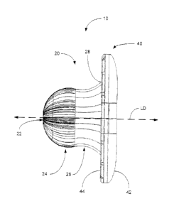
Referring now to FIG. 1. an umbilical splint 10 is shown in accordance with an
embodiment of the present invention. The umbilical splint 10 is configured
with an insertion
portion 20 terminating at an insertion end 22 and an external flange 40.
The insertion portion 20 extends in a longitudinal direction LD, shown in
dashed lines,
for insertion into an umbilicus. The insertion portion 20 includes an
insertion end 22, a
bulbous section 24 and a retaining section 26. The bulbous section 24 is
disposed between the
insertion end 22 and the retaining section 26.
The umbilical splint 10 may also include an external flange 40. The external
flange 40
is configured with an external surface 42 and an underside surface 44. The
underside surface
44 of the external flange 40 faces the insertion end 22 of the insertion
portion 20. The
insertion portion 20 and the external flange 40 may be joined at an
intersection 28.
As seen in FIG. 2A. a patient 2 has an umbilicus 3 (i.e. a belly button or
navel). As
described herein, the umbilicus 3 includes umbilical tissue 4 interior to the
umbilical opening
5. The umbilicus 3 is surrounded by abdominal tissue 6 surrounding the
umbilical opening 5.
Furthermore, the umbilical opening 5 may include a lip 7. The lip 7 may
consist of abdominal
tissue 6, such as for example, the epidermis or skin.
Referring now to FIG. 2B, the umbilical splint 10 is inserted into the patient
2 by
placing the insertion end 22 of the umbilical splint 10 into the umbilicus 3.
The bulbous
section 24 is operable to apply pressure to the umbilical tissue 4. The shape
of the bulbous
section 24 is configured to stretch or otherwise provide pressure to the
umbilical tissue 4 of
the umbilicus 3 to resist the forces of scar contracture. Furthermore, in some
embodiments,
9
CA 02859727 2014-06-18
WO 2013/102254 PCT/CA2012/000953
the insertion portion 20 is designed to engage the umbilicus 3 such that the
umbilical splint 10
is retained within umbilicus 3 without additional aid.
Upon insertion into the umbilicus 3, the retaining section 26 may be
configured to be
disposed at a level even with the umbilical opening 5. The retaining section
26 may be
configured to engage a lip 7 of the umbilicus 3. In some embodiments, the
retaining section
26 may interact with the lip 7 at the umbilical opening 5 to keep the
umbilical splint 10 within
the umbilicus 3.
In another preferred embodiment, when the insertion portion 20 of the
umbilical splint
is inserted into the umbilicus 3. the external flange 40 covers the umbilical
opening 5.
Furthermore, the external flange 40 may extend beyond the umbilical opening 5
over the
abdominal tissue 6 surrounding the umbilical opening 5. The underside surface
44 of the
external flange 40 may lie against the abdominal tissue 6 surrounding the
umbilical opening 5
and may protect the umbilicus 3 from outside moisture and debris. Similarly,
if a medicament
is used in combination with the umbilical splint 10, the external flange 40
may be operable to
contain the medicament within the umbilicus 3.
Referring now to FIG. 3, a front profile of a patient 2 is shown with an
umbilical splint
10 inserted into the umbilicus 3. As illustrated, only the exterior surface 42
of the external
flange 40 is visible, once the umbilical splint 10 is inserted into the
umbilicus 3.
To retain the umbilical splint 10 within the umbilicus 3, the umbilical splint
10 is
configured to utilize the forces applied to the components of the insertion
portion 20 to
maintain contact between the umbilical splint 10 and the patient 2. In a
preferred use, a force
CA 02859727 2014-06-18
WO 2013/102254 PCT/CA2012/000953
(not shown) is exerted by the umbilical tissue 4 of the patient 2 against the
bulbous section 24
of the insertion portion 20 to hold the umbilical splint 10 in place. For
example, in some
embodiments, enough friction and pressure may be generated by the umbilical
tissue 4 against
the bulbous section 24 to maintain the insertion portion 20 within the
umbilicus 3.
In another preferred use, a different force (not shown) may be exerted against
the
retaining section 26 to impede any longitudinal force acting to withdraw or
expunge the
umbilical splint 10 from the umbilicus 3. For example, the lip 7 of the
umbilical opening 5
may exert a force or pressure against the retaining section 26, holding the
insertion portion 20
in place within the umbilicus 3. In this manner, the retaining section 26 is
configured to aid in
positioning the umbilical splint 10 within the umbilicus 3. Furthermore, the
combination of
pressure and friction from the umbilical tissue 4 and lip 7 acting on the
bulbous section 24 and
retaining section 26, respectively, may cooperatively retain the umbilical
splint 10 within the
umbilicus 3 without any external aid.
In alternate embodiments, additional retaining means may also be utilized. For
example, tape or any other adhesive (not shown) may be used to keep the
umbilical splint 10
within the umbilicus 3. Furthermore. a bandage or any other wrapping device
may be used to
wrap the umbilical splint 10 against the abdominal tissue 6 of the patient 2,
keeping the
umbilical splint 10 in place.
Referring now to FIG. 4A ¨ FIG. 4D, umbilical splints 10A, 10B, 10C and 10D
(hereinafter referred to collectively as umbilical splints 10) are illustrated
in different
preferred embodiments. As different patients 2 may have differently sized
and/or shaped
11
CA 02859727 2014-06-18
WO 2013/102254 PCT/CA2012/000953
umbilici, the umbilical splint 1 0 may also be configured for different sizes
and/or shapes.
Furthermore, a patient 2 may desire a differently shaped umbilicus 3 than
another patient 2.
Accordin.Ldy, the appropriate umbilical splint 10 for a Oven patient 2 may be
dependent on a
preferred outcome of what the healed umbilicus 3 should look like. Values may
be dependent
on the starting size of the umbilicus 3 post-surgery. prior to weight loss or
subsequent to
pregnancy. Furthermore, the umbilical splint 10 used may be dependent on the
desired
aesthetic. Other values for the different measurements listed may be used in
alternate
embodiments. The provided values described in the preferred embodiments should
not be
construed as limiting.
Referring briefly to FIG. 1, the umbilical splint 10 includes an insertion
portion 20
having a bulbous section 24, a retaining section 26 and an intersection 28 of
the insertion
portion 20 and the external flange 40. Referring now to FIG. 4A to FIG. 4D in
view of FIG.
1, the bulbous section 24 is defined by a bulbous circumference. As the
umbilical splint 10A,
I OB, 10C, 10D are shown as substantially circular in the preferred
embodiments; the bulbous
circumference of the bulbous section 24 in the preferred embodiments is
defined by a bulbous
diameter 30 and equation (1):
Circumference 7X Diameter (1)
Similarly, a retaining circumference of the retaining section 26 of the
umbilical splint
10A, 10B, 10C, 10D may be defined by a retaining diameter 32 and equation (1).
Finally, an
openinv, circumference may be defined by an openinL, diameter 34 at the
intersection 28 of the
CA 02859727 2014-06-18
WO 2013/102254 PCT/CA2012/000953
insertion portion 20 and the external flange 40 and equation (1). The opening
circumference
may be substantially related to the size of the umbilical opening 5.
As seen in FIGs. 1 to 5, the bulbous circumference, retaining circumference
and
opening circumference may lay in one or more planes normal to the longitudinal
direction
LD. In a preferred embodiment, the bulbous. retaining and opening
circumferences are
parallel to one another. Furtheimore, although the telin circumference has
been used, it should
be understood that the cross-sectional shape of the insertion portion 20
and/or bulbous section
24. retaining section 26 and intersection 28 of the umbilical splint 10 is not
limited to a
circular shape. In other embodiments, the perimeter or cross-sectional shape
may be ovular
(as shown in FIGs. 7A to 7D and SA to SD, for example) or asymmetric, rather
than a circular
circumference. Accordingly. the circular cross-section of the insertion
portion 20, as
illustrated in Figures 1 to 5, should not be construed as limiting.
The insertion portion 20 of the umbilical splint 10 may also be defined by an
insertion
length 36 in the longitudinal direction LD. This is the length of the
umbilical splint 10 that is
inserted into the patient 2. Although dependent on a particular patient 2, the
insertion length
36 may be closely associated with the other values, shapes and/or sizes of the
insertion
portion 20 of the different umbilical splints 10.
The external flange 40 of the umbilical splint 10 may not be patient
dependent. The
external flange 40 must be large enough to extend beyond the umbilical opening
5: however,
the external flange 40 is not inserted into the umbilicus 3 and therefore, the
external flange 40
of the umbilical splint 10 may take a standard size and/or shape, as shown in
FIG. 4A through
13
CA 02859727 2014-06-18
WO 2013/102254 PCT/CA2012/000953
FIG. 4D. Similarly, as the exterior surface 42 of the eternal flange 40 is not
inserted into the
umbilicus 3, it may take on any suitable form to satisfy the aesthetic
preference of the patient
2. Different shapes, sizes, patterns, textures and the like, may be used on
the external surface
42 of the external flange 40.
In FIG. 4A ¨ FIG. 4D in view of FIG. 1, the external flange 40 includes a
flange
circumference. defined by a flange diameter 46. and a flange length 48. As the
external
flange 40 is not inserted into the umbilicus 3, the external flange in each of
FIG. 4A ¨ FIG.
4D is standard with a flange diameter of 21.00mm and a flange length of
2.71mm. These
values should not be construed as limiting as other values are possible in
various
embodiments.
Table 1 provides a listing of the different values for the preferred
embodiments of the
umbilical splint 10A, 10B, I OC, I OD illustrated in FIG. 4A to FIG. 4D.
Table 1: Measured Values of the Preferred Embodiments
(in mm) Umbilical Splint Umbilical Splint Umbilical Splint Umbilical
Splint
10A (FIG. 4A) 10B (FIG. 4B) 10C (FIG. 4C) 10D (FIG. 4D)
Bulbous Circ. 8.04 7 10.00 7 12.00 7 14.00 7
Retainer Circ. 7.77 77 9.21 7 11.91 7r 12.69w
Opening Circ. 10.00 7 12.00 7 14.00 7 14.00 7
Insertion
8.07 10.00 12.00 12.00
Length
Flange Circ. 21.00 7 21.00 7 21.00 7 21.00 7
Flange Length , 2.71 2.71 2.71 2.71
14
CA 02859727 2014-06-18
WO 2013/102254 PCT/CA2012/000953
In seen in FIG. 4A, the insertion end 22 is substantially planar. A planar
insertion end
21 (i.e. a flat bottom) may be desirable for some patients. In other
embodiments, as illustrated
in FIG. 4B ¨ FIG. 4D. the insertion end 22 may be rounded.
As also seen in FIG. 4A ¨ FIG. 4D, particular ratios between the bulbous
circumference and retaining circumference have been discovered to be
particularly
advantageous. The ratios may be based upon the bulbous diameter 30 and the
retaining
diameter 32. Table 2 provides a listing of the bulbous circumference to
retaining
circumference described in the preferred embodiments illustrated in FIG. 4A ¨
FIG. 4D:
Table 2: Calculating Bulbous Circ. to Retaining Circ. Ratios
Bulbous Retainino-
(in mm).Ratio
Diameter 0 Diameter 32
10A (FIG. 4A) 8.04 7.2y2 1.11
10B (FIG. 4B) 10.00 9.21 1.09
10C. (FIG. 4C) 12.00 11.91 1.01
10D (FIG. 4D) 14.00 12.69 1.10
Although the above ratios are described with respect to preferred embodiments,
it
should be understood that additional ratios relating, the bulbous
circumference to the retaining
circumference are also possible. For example. in some embodiments a ratio of
1.2 to 1.4 may
be particularly desirable.
Referring- now to FIG. 5, an application layer 50 is applied to the insertion
portion 20
of the umbilical splint 10. For example, the application layer 50 may include
a medicament
or a silicone gel sheet. For example, an antibiotic may be used to reduce the
chances of
infection. Furthermore, other foims of silicone than silicone 2e1 sheets may
be added. The
CA 02859727 2014-06-18
WO 2013/102254 PCT/CA2012/000953
external flange 40 of the umbilical splint 10 is then operable to contain the
medicament within
the umbilicus 3 when laid securely against the abdominal tissue 6 surrounding
the umbilical
opening. 5.
If the application laver 50 comprises a silicone gel sheet, the silicone gel
sheet is used
to reduce the effects of scarring. The inventors have appreciated that the
umbilical splint 10 is
ideal for providing constant pressure to the umbilical tissue 4. This pressure
may also be used
to apply silicone against the umbilical tissue 4 of the umbilicus 3 to promote
healing and
improve the overall cosmesis of the area. When placed on the exterior of the
insertion portion
20, the application layer 50 comprising a silicone gel sheet is operable to be
pressed up
against the walls of the umbilicus 3 for as long as the umbilical splint 10 is
retained within the
umbilicus 3. As silicone is known to reduce the appearance of scarring, the
umbilical splint
can combine both pressure and silicone against the umbilical tissue 4 to aid
in the healing- of
the umbilicus 3, for example, after an abdominal operation.
Although the application layer 50 in FIG. 5 is shown surrounding the entire
insertion
portion 20, it should be understood that a more localized application layer 50
may also be
used. For example, the application layer 50 may surround the insertion end 22
and/or bulbous
section 24 only, without extending over the retaining section 26.
A flow chart illustrating a method 60 of using an umbilical splint 10 is now
shown in
FIG. 6. In Block 61, the umbilical splint 10 is inserted into an umbilicus 3
after an abdominal
operation. As described in reference to FIG. 1, the umbilical splint comprises
an insertion
portion 20 extending in a longitudinal direction LD and terminating at an
insertion end 27.
16
CA 02859727 2014-06-18
WO 2013/102254 PCT/CA2012/000953
Next, in Block 62, the umbilical splint 10 is retained within the umbilicus 3
using a
retaining section 26 to engage the umbilicus 3. For example, the retaining
section 26 may
engage a lip 7 of the umbilical opening 5 to impede any withdrawal or
expunging force acting
on the umbilical splint 10.
Once inserted into the umbilicus 3, in Block 63, the umbilical splint 10
applies
pressure to the umbilicus 3 using a bulbous section 24 of the insertion
portion 20 to shape the
umbilicus 3 after the abdominal operation. In a preferred embodiment, as seen
in Block 64,
the bulbous section 24 of the umbilical splint 10 counteracts scar contracture
of the umbilicus
3 by applying pressure to a scar.
Finally, in Block 65, the umbilical splint 10 is maintained within the
umbilicus 3 for a
period of time until the umbilicus 3 has healed from the abdominal operation.
While lengths
will vary by patient 2, different approaches may be used.
In a preferred embodiment, a patient 2 may use the umbilical splint 10
continuously.
The umbilical splint 10 may be removed for personal hygiene purposes such as
cleaning the
umbilicus 3, applying medication to the umbilicus 3 or scar, applying an
application layer 50
to the insertion portion 20 of the umbilical splint 10 and/or washing the
umbilical splint 10.
Otherwise, the umbilical splint 10 may be retained within the umbilicus 3
until the umbilicus
3 has healed.
In another preferred embodiment, the patient 2 may use multiple umbilical
splints 10
during the healing process. For example, the patient 2 may begin with a first
umbilical splint
having a relatively small bulbous section 24. The bulbous section 24 is
configured with a
17
CA 02859727 2014-06-18
WO 2013/102254 PCT/CA2012/000953
first bulbous circumference. Subsequently, as the umbilicus 3 of the patient 2
heals. the
patient 2 may progress to one or more larger umbilical splints 10 having
progressively larger
bulbous sections 24 (and corresponding larger bulbous circumferences). In this
manner, the
umbilical splint 10 will continue to apply pressure to the umbilicus 3 as the
umbilicus 3 heals
and may allow the umbilical splint 10 to progressively shape the umbilicus 3
after an
abdominal operation.
In other embodiments, the patient 2 may use or begin to use the umbilical
splint 10 for
repeated brief periods of time. For example, a patient 2 may use the umbilical
splint three
times a day for 20 minute intervals. In other embodiments, a patient 2 may
insert the
umbilical splint 2 for longer periods of hours, days or weeks. Furthermore,
different regimens
may be used to steadily increase the period of time the umbilical splint 10 is
worn by the
patient 2. The patient 2 may continue to use the umbilical splint 10 until the
umbilicus 3 has
healed from the abdominal operation or the chance of scar contracture is
reduced or no longer
present.
Although the insertion portion 20 of the umbilical splint 10 has been
illustrated in
FIGs. 1 to 5 as being round such that its bulbous circumference and retaining
circumference
have a substantially circular cross-section, it should be understood that
other shapes, sizes and
perimeters for the insertion portion 20 are possible. For example, as
illustrated in FIGs. 7A to
7D and FIGs. SA to 81), the insertion portion 20 of umbilical splint 10 is
shaped such that its
bulbous circumference and retaining circumference are substantially ovular or
non-circular,
with different major and minor axes.
18
CA 02859727 2014-06-18
WO 2013/102254 PCT/CA2012/000953
In some embodiments, the inventors have appreciated that bulbous and retaining
circumferences having an oval or ovular shape are better retained within the
umbilicus 3
compared to circular bulbous. retaining and/or opening circumferences.
Furthermore. an
ovular insertion portion 20 may result in a more pleasing umbilicus 3, once
the umbilicus 3
has healed.
In other embodiments. the bulbous, retaining and/or opening circumferences may
be
asymmetric and/or different shapes from each other. For example. in one
embodiment, the
bulbous circumference may be an asymmetric shape, or even free-form, and the
retaining
circumference may be ovular. It should be understood that other shapes and
configurations
for the insertion portion 20 are possible and that the bulbous circumference,
retaining
circumference and opening circumference are not limited to the shapes
described herein.
Referring now to FIGs. 7A to 7D. an umbilical splint 10E having an insertion
portion
20 with an ovular opening circumference or cross-section is shown. Many
features of
umbilical splint 10 are similar to those previously described, such as the
flange length 48 and
insertion length 36. In FIG. 7B, a top view of the umbilical splint 10E
illustrates a circular
external flange 40. However, as previously mentioned, other shapes for the
external flange 40
are also possible.
Referring to FIG. 7A. the umbilical splint 10E having an ovular insertion
portion 20 is
configured with an ovular bulbous circumference and an ovular opening
circumference. As
seen in FIG. 7C and FIG. 7D in front and side profile view, with the major
axes (+) larger
than the minor axes (-). such that each of the bulbous diameters 30E+, 30E-
and opening
19
CA 02859727 2014-06-18
WO 2013/102254 PCT/CA2012/000953
diameters 34E+, 34E- are different from front-to-back and side-to-side. As
shown in FIG. 7C,
a front view of the umbilical splint 10E is shown with a major bulbous
diameter 30E+ and a
major opening diameter 34E+. In comparison to the side profile view in FIG.
7D, the major
bulbous diameter 30E+ and the major opening diameter 34E+, seen in FIG. 7C,
are larger
than the minor bulbous diameter 30E- and the minor opening diameter 34E-,
respectively.
Such an ovular insertion portion 20 may provide a better distribution of
pressure to the
umbilical tissue 4 when placed inside the umbilicus 3. Furthermore, the shape
may allow the
umbilical splint 10E to stay retained within the umbilicus 3 unaided.
Different shapes may
also provide improved comfort for patients 2 than insertion portions 20 having
circular or
ovular shapes.
A similar relationship can be seen in the umbilical splint 1OF shown in FIGs.
8A to
8D. The major bulbous diameter 30E-, seen in front view in FIG. 8C, is larger
than the minor
bulbous diameter 30E-, seen in side profile view in FIG. 8D. Similarly, the
major opening
diameter 34F+, seen in front view in FIG. 8C, is larger than the minor opening
diameter 34F-,
seen in side profile view in FIG. 8D. A similar relationship may exist with
the retaining
circumference haviml, different side-to-side and front-to-back retaining
diameters (not shown).
Finally, it should be understood that while the umbilical splints 10 and 10A
to 1OF
have been described with respect to specific shapes, other shapes are also
possible.
Furthermore, the umbilical splints 10 and 10A to 10F, as described herein, may
be constructed
in different sizes for different sized patients 2, from infants and small
children to adults.
CA 02859727 2014-06-18
WO 2013/102254 PCT/CA2012/000953
Although this disclosure has described and illustrated certain preferred
embodiments
of the invention, it is also to be understood that the invention is not
restricted to these
particular embodiments rather, the invention includes all embodiments which
are functional,
or mechanical equivalents of the specific embodiments and features that have
been described
and illustrated herein. Similarly, the scope of the claims should not be
limited by the preferred
embodiments set forth in the examples, but should be Oven the broadest
interpretation
consistent with the description as a whole.
It will be understood that, although various features of the invention have
been
described with respect to one or another of the embodiments of the invention,
the various
features and embodiments of the invention may be combined or used in
conjunction with
other features and embodiments of the invention as described and illustrated
herein.