Note: Descriptions are shown in the official language in which they were submitted.
CA 02859810 2014-10-09
DELIVERING OCULAR IMPLANTS INTO THE EYE
FIELD
[0002] The present invention relates generally to the medical devices
and treatments for
the eye. More particularly, the present invention relates to systems, devices
and methods for
delivering ocular implants into the eye for treating glaucoma.
BACKGROUND
[0003] According to a draft report by The National Eye Institute (NEI) at
The United
States National Institutes of Health (NIH), glaucoma is now the leading cause
of irreversible
blindness worldwide and the second leading cause of blindness, behind
cataract, in the world.
Thus, the NET draft report concludes, "it is critical that significant
emphasis and resources
continue to be devoted to determining the pathophysiology and management of
this disease."
Glaucoma researchers have found a strong correlation between high intraocular
pressure and
glaucoma. For this reason, eye care professionals routinely screen patients
for glaucoma by
measuring intraocular pressure using a device known as a tonometer. Many
modern
tonometers make this measurement by blowing a sudden puff of air against the
outer surface
of the eye.
[0004] The eye can be conceptualized as a ball filled with fluid. There are
two types of
fluid inside the eye. The cavity behind the lens is filled with a viscous
fluid known as
vitreous humor. The cavities in front of the lens are filled with a fluid
known as aqueous
humor. Whenever a person views an object, he or she is viewing that object
through both the
vitreous humor and the aqueous humor.
[0005] Whenever a person views an object, he or she is also viewing that
object through
the cornea and the lens of the eye. In order to be transparent, the cornea and
the lens can
include no blood vessels. Accordingly, no blood flows through the cornea and
the lens to
provide nutrition
- 1 -
CA 02859810 2014-06-18
WO 2013/096453 PCT/US2012/070626
to these tissues and to remove wastes from these tissues. Instead, these
functions are performed
by the aqueous humor. A continuous flow of aqueous humor through the eye
provides nutrition
to portions of the eye (e.g., the cornea and the lens) that have no blood
vessels. This flow of
aqueous humor also removes waste from these tissues.
[0007] Aqueous humor is produced by an organ known as the ciliary body. The
ciliary body
includes epithelial cells that continuously secrete aqueous humor. In a
healthy eye, a stream of
aqueous humor flows out of the anterior chamber of the eye through the
trabecular meshwork
and into Schlemm's canal as new aqueous humor is secreted by the epithelial
cells of the ciliary
body. This excess aqueous humor enters the venous blood stream from Schlemm's
canal and is
carried along with the venous blood leaving the eye.
[0008] When the natural drainage mechanisms of the eye stop functioning
properly, the
pressure inside the eye begins to rise. Researchers have theorized prolonged
exposure to high
intraocular pressure causes damage to the optic nerve that transmits sensory
information from the
eye to the brain. This damage to the optic nerve results in loss of peripheral
vision. As
glaucoma progresses, more and more of the visual field is lost until the
patient is completely
blind.
[0009] In addition to drug treatments, a variety of surgical treatments
for glaucoma have
been performed. For example, shunts were implanted to direct aqueous humor
from the anterior
chamber to the extraocular vein (Lee and Scheppens, "Aqueous-venous shunt and
intraocular
pressure," Investigative Ophthalmology (Feb. 1966)). Other early glaucoma
treatment implants
led from the anterior chamber to a sub-conjunctival bleb (e.g., US 4,968,296
and US 5,180,362).
Still others were shunts leading from the anterior chamber to a point just
inside Schlemm's canal
(Spiegel et al., "Schlemm's canal implant: a new method to lower intraocular
pressure in patients
with POAG?" Ophthalmic Surgery and Lasers (June 1999); US 6,450,984; US
6,450,984).
SUMMARY OF THE DISCLOSURE
[00010] One aspect of the invention provides a method of deploying an ocular
implant into
Schlemm's canal of an eye. In some embodiments, the method includes the steps
of inserting a
distal end of a cannula through a cornea of the eye and into an anterior
chamber of the eye, the
cannula having a distal opening extending from the distal end and through a
side wall; placing
the distal opening of the cannula into fluid communication with Schlemm's
canal; advancing the
ocular implant distally through the cannula with a delivery tool engaged with
the ocular implant,
a proximal portion of the ocular implant engaging the delivery tool proximal
to a distal portion
of the delivery tool; and disengaging the ocular implant and the delivery tool
when the proximal
portion of the ocular implant reaches the cannula distal opening.
- 2 -
CA 02859810 2014-06-18
WO 2013/096453 PCT/US2012/070626
1000111 In some embodiments, the disengaging step includes the step of
separating the distal
portion of the delivery tool and the ocular implant from each other when the
distal portion of the
delivery tool passes through the distal opening of the cannula. In some such
embodiments, the
separating step is performed before the distal portion of the delivery tool
reaches the distal end of
the cannula. The separating step may include the step of maintaining contact
between the ocular
implant and the cannula and moving the distal portion of the delivery tool
away from the
cannula. In embodiments in which the distal portion of the delivery tool has
an at-rest shape
(such as, e.g., a curve having a smaller radius of curvature than a distal
portion of the cannula),
the separating step may also include the step of permitting the distal portion
of the delivery tool
to assume its at-rest shape.
[00012] In some embodiments, the inserting step includes the step of placing
the distal end of
the cannula in Schlemm's canal and a portion of the cannula distal opening
outside of
Schlemm's canal, the disengaging step including the step of disengaging the
ocular implant and
the delivery tool while the proximal portion of the ocular implant is disposed
outside of
Schlemm's canal. The disengaging step may also include the step of disengaging
the ocular
implant and the delivery tool while the proximal portion of the ocular implant
is disposed inside
the anterior chamber of the eye.
[00013] Some embodiments include the step of, after the disengaging step: re-
engaging the
delivery tool and the ocular implant; moving the delivery tool and the ocular
implant in a
proximal direction to withdraw at least a portion of the ocular implant from
Schlemm's canal;
advancing the ocular implant and delivery tool distally into Schlemm's canal;
and disengaging
the ocular implant and the delivery tool.
[00014] The method's disengaging step may also include the step of disengaging
an
interlocking portion of the delivery tool from a complementary interlocking
portion of the ocular
implant.
[00015] Another aspect of the invention provides a system with a cannula
having a side wall
defining a passageway, the cannula including an opening extending through a
distal end and the
side wall, the opening fluidly communicating with the passageway; an ocular
implant disposed
inside the passageway defined by the cannula; a delivery tool having a distal
interlocking portion
engaging a complementary interlocking portion of the ocular implant to form a
mechanically
interlocking connection when the interlocking portion of the delivery tool is
proximal to the
trough portion of the cannula.
[00016] In some embodiments, the distal interlocking portion of the delivery
tool has an at-
rest shape different from the shape of the cannula (such as, e.g., a curve
having a smaller radius
of curvature than a radius of curvature of the cannula), the cannula side wall
preventing the
- 3 -
CA 02859810 2014-06-18
WO 2013/096453 PCT/US2012/070626
delivery tool from assuming its at-rest shape when the interlocking portion of
the delivery tool is
proximal to the trough portion of the cannula.
[00017] In some embodiments, the system also has a cannula subassembly
including the
cannula and a delivery tool subassembly including the delivery tool, the
delivery tool
subassembly and the cannula subassembly engaging one another at a keyed
interface, the keyed
interface being configured to permit the delivery tool to slide along the
passageway defined by
the cannula, and the keyed interface being configured to prohibit rotation of
the delivery tool
subassembly relative to the cannula subassembly so that a predetermined
orientation between the
delivery tool and the cannula is maintained.
[00018] In some embodiments, the delivery tool subassembly includes a rotating
rack gear
defining a shaped hole having a predetermined shape in lateral cross-section
and the cannula
subassembly including a shaped portion configured to cooperate with the shaped
hole of the
rotating rack gear so that the delivery tool is free to slide along the
passageway defined by the
cannula and rotation of the delivery tool relative to the cannula is
prohibited.
[00019] In some embodiments, the opening extending through the distal end and
the side wall
of the cannula is dimensioned and positioned such that, when the ocular
implant reaches a
predefined location along the passageway, the delivery tool will move toward
an undeformed
shape in which the interlocking portion of the delivery tool disengages the
complementary
interlocking portion of the ocular implant to release the ocular implant. The
delivery tool may
also have a cannula wall engagement surface diametrically opposite the
interlocking portion and
a reduced diameter portion proximal to the interlocking portion.
[00020] In some embodiments, the mechanically interlocking connection is
configured to
preclude axial and/or movement of the ocular implant relative to the delivery
tool. The
mechanically interlocking connection may include a peak of the delivery tool
that is received in a
valley of the ocular implant or a peak of the ocular implant that is received
in a valley of the
delivery tool.
[00021] In some embodiments, the system also includes a motion control
mechanism
configured to be operated from a location outside of the eye to move the
delivery tool and the
ocular implant along the passageway defined by the cannula.
[00022] In some embodiments, a system configured to deliver an ocular implant
into
Schlemm's canal of an eye is provided, comprising a curved cannula sized and
configured to be
advanced partially inside Schlemm's canal, the cannula having a distal trough
portion which
defines an open groove and a lumen extending along a length of the cannula
into the distal
trough portion, and a delivery tool slidably insertable into the lumen of the
cannula, the delivery
tool having a distal interlocking portion configured to mechanically interlock
with a proximal
- 4 -
CA 02859810 2014-06-18
WO 2013/096453 PCT/US2012/070626
interlocking portion of the ocular implant, the delivery tool being biased to
bend radially through
the open groove of the distal trough portion to disengage from the ocular
implant when the distal
interlocking portion of the delivery tool is advanced into the distal trough
portion of the cannula.
[00023] In one embodiment, the delivery tool further comprises a ribbon
portion proximal to
the distal interlocking portion that is biased to assume a curved resting
shape when no external
forces are acting thereon.
[00024] In some embodiments, the ribbon portion is sized and configured to
track along the
widest part of an interior of the lumen of the cannula.
[00025] In other embodiments, a thickness of the ribbon portion is selected so
as to enable the
ribbon portion to preferentially bend along a preferential bending plane.
[00026] In alternative embodiments, the delivery tool is oriented within the
cannula so that the
preferential bending plane of the ribbon portion is co-planar with a curvature
plane of the
cannula.
[00027] In some embodiments, the ocular implant and the distal interlocking
portion of the
delivery tool both have an outer diameter slightly smaller than an inner
diameter of the lumen of
the cannula so that the distal interlocking portion can form a mechanically
interlocking
connection with the proximal interlocking portion of the ocular implant, the
mechanically
interlocking connection being configured to prevent jamming and unintentional
release of the
ocular implant.
[00028] In another embodiment, the distal trough portion has a trough depth
greater than a
height of the ocular implant so that a distal end of the ocular implant will
travel between an inner
surface of the distal trough portion and tissue stretched over the distal
trough portion as the
ocular implant is advanced.
[00029] In alternative embodiments, the cannula has a radius of curvature that
is smaller than
a radius of curvature of the ocular implant.
[00030] In one embodiment, the ribbon portion of the delivery tool has a
resting radius of
curvature that is smaller than a radius of curvature of the cannula.
[00031] In another embodiment, an ocular implant and delivery system,
comprising an ocular
implant sized and configured to be implanted inside Schlemm's canal of an eye,
the ocular
implant comprising a proximal interlocking portion, a curved cannula sized and
configured to be
advanced partially inside Schlemm's canal, the cannula having a distal trough
portion which
defines an open groove and a lumen extending along a length of the cannula
into the distal
trough portion, and a delivery tool slidably insertable into the lumen of the
cannula, the delivery
tool having a distal interlocking portion configured to mechanically interlock
with the proximal
interlocking portion of the ocular implant, the delivery tool being biased to
bend radially through
- 5 -
CA 02859810 2014-06-18
WO 2013/096453 PCT/US2012/070626
the open groove of the distal trough portion to disengage from the ocular
implant when the distal
interlocking portion of the delivery tool is advanced into the distal trough
portion of the cannula.
[00032] In one embodiment, the delivery tool further comprises a ribbon
portion proximal to
the distal interlocking portion that is biased to assume a curved resting
shape when no external
forces are acting thereon.
[00033] In some embodiments, the ribbon portion is sized and configured to
track along the
widest part of an interior of the lumen of the cannula.
[00034] In other embodiments, a thickness of the ribbon portion is selected so
as to enable the
ribbon portion to preferentially bend along a preferential bending plane.
[00035] In alternative embodiments, the delivery tool is oriented within the
cannula so that the
preferential bending plane of the ribbon portion is co-planar with a curvature
plane of the
cannula.
[00036] In some embodiments, the ocular implant and the distal interlocking
portion of the
delivery tool both have an outer diameter slightly smaller than an inner
diameter of the lumen of
the cannula so that the distal interlocking portion can form a mechanically
interlocking
connection with the proximal interlocking portion of the ocular implant, the
mechanically
interlocking connection being configured to prevent jamming and unintentional
release of the
ocular implant.
[00037] In another embodiment, the distal trough portion has a trough depth
greater than a
height of the ocular implant so that a distal end of the ocular implant will
travel between an inner
surface of the distal trough portion and tissue stretched over the distal
trough portion as the
ocular implant is advanced.
[00038] In alternative embodiments, the cannula has a radius of curvature that
is smaller than
a radius of curvature of the ocular implant.
[00039] In one embodiment, the ribbon portion of the delivery tool has a
resting radius of
curvature that is smaller than a radius of curvature of the cannula.
[00040] A system for delivering an ocular implant into Schlemm's canal of an
eye, the ocular
implant comprising a wall having a wall thickness is also provided, the system
comprising a
cannula comprising a cannula wall, the cannula wall including first portion
and a second portion,
both portions of the cannula wall extending along a longitudinal center axis
having a curved
portion, the first portion of the cannula wall being disposed on a radially
inward side of the
longitudinal center axis and the second portion of the cannula wall being
disposed on radially
outward side of the longitudinal center axis, the cannula wall defining a
trough opening through
the first portion of the cannula wall and a lumen extending from the trough to
a proximal end of
the cannula, the cannula wall being sized and configured so that the trough
and the lumen define
- 6 -
CA 02859810 2014-06-18
WO 2013/096453
PCT/US2012/070626
a pathway extending from a location outside of the eye to a location inside
Schlemm's canal
when a distal point of the cannula is inside Schlemm's canal of the eye, a
delivery tool extending
into the lumen of the cannula, the delivery tool comprising a proximal
portion, a distal
interlocking portion, and a ribbon portion extending between the proximal
portion and the distal
interlocking portion, the distal interlocking portion of the delivery tool
forming a mechanically
interlocking connection with a complementary interlocking portion of the
ocular implant when
disposed in the lumen of the cannula, and the distal interlocking portion of
the delivery tool
moving through the trough opening of the cannula when the distal interlocking
portion of the
delivery tool reaches a predetermine location along the pathway so that the
mechanically
interlocking connection is broken.
[00041] In some embodiments, the ribbon portion of the delivery tool is biased
to assume a
curved resting shape when no external forces are acting thereon, the ribbon
portion the delivery
tool moves toward the curved resting shape when the delivery tool reaches the
predetermined
location along the pathway, and the interlocking portion of the delivery tool
disengages the
complementary interlocking portion of the ocular implant when the delivery
tool is free to move
toward the curved resting shape.
[00042] In other embodiments, the ribbon portion has an outer diameter and a
thickness
extending between a first major side of the ribbon portion and a second major
side of the ribbon
portion, and the outer diameter of the ribbon portion is only slightly smaller
than the inner
diameter of the cannula so that the ribbon portion tracks along the widest
part of the cannula
lumen and so that support provided by the cannula wall makes it less likely
that ribbon portion
will buckle.
[00043] In another embodiment, the outer diameter of the ribbon portion is
smaller than the
inner diameter of the cannula by a clearance value. In one embodiment, the
clearance value is
less than two times the wall thickness of the ocular implant. In other
embodiments, the clearance
value is between about 0.0005 inches and about 0.0010 inches.
[00044] In some embodiments, the thickness of the ribbon portion is selected
so that the
ribbon portion preferentially bends along a preferential bending plane. In
another embodiment,
an aspect ratio of the diameter to the thickness is selected so that the
ribbon portion preferentially
bends along a preferential bending plane.
[00045] In some embodiments, the delivery tool is oriented within the cannula
so that a
preferential bending plane of the ribbon portion is co-planar with a curvature
plane of the
cannula, the curvature plane being defined by the central axis of the cannula.
[00046] In some embodiments, the ocular implant and the distal interlocking
portion of the
delivery tool both have an outer diameter slightly smaller than the inner
diameter of the cannula
- 7 -
CA 02859810 2014-06-18
WO 2013/096453 PCT/US2012/070626
so that the distal interlocking portion can form a mechanically interlocking
connection with the
complimentary interlocking portion of the ocular implant, the mechanically
interlocking
connection being configured to prevent jamming and unintentional release of
the ocular implant.
[00047] In some embodiments, the outer diameter of both the ocular implant and
the distal
interlocking portion of the delivery tool is smaller than the inner diameter
of the cannula by a
clearance value. In another embodiment, the clearance value is less than two
times the wall
thickness of the ocular implant. In another embodiment, the clearance value is
between about
0.0005 inches and about 0.0010 inches.
[00048] In some embodiments, the trough opening has a width that is
substantially equal to an
inner diameter of the cannula and both the ribbon portion and the distal
interlocking portion of
the delivery tool have an outer diameter slightly smaller than the inner
diameter of the cannula so
that so that a distal portion of the delivery tool can pass through the trough
opening when the
delivery tool reaches the predetermined location along the pathway defined by
the cannula.
[00049] In another embodiment, the outer diameter of both the ribbon portion
and the distal
interlocking portion of the delivery tool is smaller than the inner diameter
of the cannula by a
clearance value. In some embodiments, the clearance value is less than two
times the wall
thickness of the ocular implant. In other embodiments, the clearance value is
between about
0.0005 inches and about 0.0010 inches.
[00050] In one embodiment, the trough has a trough depth greater than a height
of the implant
so that the distal end of the ocular implant will travel between an inner
surface of the cannula and
tissue stretched over the trough as the ocular implant is advanced along the
path defined by the
lumen and the trough.
[00051] In other embodiments, the trough is symmetrical about a curvature
plane of the
cannula so that the cannula can be used by both left handed users and right
handed users in
substantially the same way.
[00052] In an additional embodiment, the curved portion of the longitudinal
central axis of the
cannula has a radius of curvature that is smaller than a radius of curvature
of the ocular implant.
[00053] In some embodiments, the ribbon portion of the delivery tool has a
resting radius of
curvature that is smaller than a radius of curvature of the curved portion of
the longitudinal
central axis of the cannula.
[00054] In another embodiment, a delivery tool subassembly and a cannula
subassembly of
the system engage one another at a keyed interface, the keyed interface being
configured to
permit the delivery tool to slide along the passageway defined by the cannula
and the keyed
interface being configured to prohibit rotation of the delivery tool
subassembly relative to the
- 8 -
CA 02859810 2014-06-18
WO 2013/096453
PCT/US2012/070626
cannula subassembly so that a coplanar relationship between a bending plane of
the ribbon
portion and a curvature plane of the cannula is maintained.
[00055] In one embodiment, the distal interlocking portion of the delivery
tool engages the
complementary interlocking portion of the ocular implant to form a
mechanically interlocking
connection when the distal interlocking portion of the delivery tool is
disposed in the lumen of
the cannula.
[00056] In another embodiment, the cannula wall holds the ribbon portion of
the delivery tool
in a deformed shape when the distal interlocking portion of the delivery tool
is disposed in the
lumen of the cannula.
[00057] A cannula for delivering an ocular implant into Schlemm's canal of an
eye, the ocular
implant having an implant height is provided, the cannula comprising a body
comprising a first
side and a second side, both sides of the body extending along a longitudinal
center axis having a
curved portion, the first side of the body being disposed on a radially inward
side of the
longitudinal center axis and the second side of the body being disposed on
radially outward side
of the longitudinal center axis, a tapered distal tip extending distally from
the second side of the
body, the body defining a trough that opens through the first side of the body
and a lumen that
extends from the trough to a proximal end of the body, the body being sized
and configured so
that the trough and the lumen define a pathway extending from a location
outside of the eye to a
location inside Schlemm's canal when a distal point of the tapered distal tip
is inside Schlemm's
canal of the eye, the tapered distal tip being shaped and configured to
stretch Schlemm's canal
tissues over a portion of the trough as the tapered distal tip is advanced
into Schlemm's canal,
and the trough having a trough depth greater than the implant height so that
the distal end of the
ocular implant will travel between an inner surface of the cannula and the
tissue stretched over
the trough as the ocular implant is advanced along the path defined by the
lumen and the trough.
[00058] In some embodiments, the curved portion of the longitudinal central
axis defines a
curvature plane.
[00059] In other embodiments, the trough is symmetrical about the curvature
plane. In an
additional embodiment, the distal tip is symmetrical about the curvature
plane.
[00060] In some embodiments, the trough comprises a first trough edge, a
second trough
edge, and an intermediate portion extending between the first trough edge and
the second trough
edge, the intermediate portion having a semi-circular transverse cross-
sectional shape.
[00061] In another embodiment, the tip portion comprises a first leading edge,
a second
leading edge, and a semi-circular transverse cross-section extending between
the first leading
edge and the second leading edge.
- 9 -
CA 02859810 2014-06-18
WO 2013/096453
PCT/US2012/070626
[00062] In one embodiment, a tip chord extending between the first leading
edge and the
second leading edge has a chord length that increases as the tip portion
extends proximally from
a distal point thereof.
[00063] In some embodiments, the first leading edge has a first length and the
second leading
edge has a second length that is substantially equal to the first length.
[00064] In other embodiments, the first leading edge and the second leading
edge extend
=
between an inside surface of the body and an outside surface of the body.
[00065] In another embodiment, the inside surface of the body comprises a
concave surface
and the outside surface of the body comprises a convex surface.
[00066] In some embodiments, the first leading edge and the second leading
edge both
distally converge toward the distal point so that the tapered distal tip is
generally V-shaped when
viewed in plan.
[00067] In an additional embodiment, the distal point of the tip portion is
sufficiently blunt to
slide along the outer major wall of Schlemm's canal without cutting sclera]
tissue underlying the
outer major wall of Schlemm's canal.
[00068] In some embodiments, at least a portion of the body is tubular.
[00069] In another embodiment, a curved portion of the body is shaped and
dimensioned to be
received inside the anterior chamber while a tubular portion of the body is
extending through an
incision in the dome shaped wall and the distal point of the body is inside
Schlemm's canal.
[00070] In some embodiments, the curved portion of the longitudinal central
axis has a radius
of curvature that is substantially constant along a length thereof.
[00071] In another embodiment, the curved portion of the longitudinal central
axis has a
radius of curvature that varies along a length thereof.
1000721 In another embodiment, the curved portion of the longitudinal central
axis has a
radius of curvature that is smaller than a radius of curvature of the ocular
implant.
[00073] In some embodiments, the body has a curved portion extending to the
distal tip.
[00074] In some embodiments, the curved portion of the body has an angular
span greater
than 90 degrees.
[00075] In another embodiment, the curved portion of the body has an angular
span of about
140.
[00076] In an additional embodiment, the trough depth extends between an inner
surface of
the body and a chord extending between a first trough edge and a second trough
edge.
- 10 -
CA 02859810 2014-10-09
[00076a] In one aspect, there is provided a method of deploying an
ocular implant into
Schlemm's canal of an eye, comprising: inserting a distal end of a curved
distal portion of a
cannula through a cornea of the eye and into an anterior chamber of the eye,
the cannula
comprising a distal opening and a trough extending from the distal end and
through a side
wall; placing the distal opening of the cannula into fluid communication with
Schlemm's
canal; advancing the ocular implant distally through the cannula with a
delivery tool engaged
with the ocular implant, a proximal portion of the ocular implant engaging the
delivery tool
proximal to a distal portion of the delivery tool, the delivery tool having a
curved at-rest shape
with a smaller radius of curvature than the radius of curvature of the distal
portion of the
cannula; and disengaging the ocular implant and the delivery tool when the
proximal portion
of the ocular implant reaches the cannula distal opening by permitting the
delivery tool to
move toward its at-rest shape.
100076b1 In another aspect, there is provided a system comprising: a
cannula having a
side wall defining a passageway, the cannula having a curved distal portion
extending
between a distal end and a proximal portion along a radius of curvature, the
cannula including
an opening extending through the distal end and the side wall to form a trough
portion, the
opening fluidly communicating with the passageway; an ocular implant disposed
inside the
passageway defined by the cannula; and a delivery tool having a distal
interlocking portion
engaging a complementary interlocking portion of the ocular implant to form a
mechanically
interlocking connection when the interlocking portion of the delivery tool is
proximal to the
trough portion of the cannula, the delivery tool distal interlocking portion
having a curved at-
rest shape having a smaller radius of curvature than the radius of curvature
of the cannula
distal portion, the cannula side wall preventing the delivery tool distal
interlocking portion
from assuming its at-rest shape when the delivery tool distal interlocking
portion is proximal
to the trough portion of the cannula.
100076c1 In another aspect, there is provided a system configured to
deliver an ocular
implant into Schlemm's canal of an eye, comprising: a curved cannula sized and
configured to
be advanced partially inside Schlemm's canal, the cannula having a distal
trough portion
which defines an open groove and a lumen extending along a length of the
cannula into the
distal trough portion; and a delivery tool slidably insertable into the lumen
of the cannula, the
- 10a -
CA 02859810 2014-10-09
delivery tool having a distal interlocking portion configured to mechanically
interlock with a
proximal interlocking portion of the ocular implant, the delivery tool being
biased to bend
radially through the open groove of the distal trough portion to disengage
from the ocular
implant when the distal interlocking portion of the delivery tool is advanced
into the distal
trough portion of the cannula.
[00076d] In another aspect, there is provided an ocular implant and
delivery system,
comprising: an ocular implant sized and configured to be implanted inside
Schlemm's canal
of an eye, the ocular implant comprising a proximal interlocking portion; a
curved cannula
sized and configured to be advanced partially inside Schlemm's canal, the
cannula having a
distal trough portion which defines an open groove and a lumen extending along
a length of
the cannula into the distal trough portion; and a delivery tool slidably
insertable into the
lumen of the cannula, the delivery tool having a distal interlocking portion
configured to
mechanically interlock with the proximal interlocking portion of the ocular
implant, the
delivery tool being biased to bend radially through the open groove of the
distal trough
portion to disengage from the ocular implant when the distal interlocking
portion of the
delivery tool is advanced into the distal trough portion of the cannula.
[00076e] In another aspect, there is provided a system for delivering
an ocular implant
into Schlemm's canal of an eye, the ocular implant comprising a wall having a
wall thickness,
the system comprising: a cannula comprising a cannula wall, the cannula wall
including first
portion and a second portion, both portions of the cannula wall extending
along a longitudinal
center axis having a curved portion, the first portion of the cannula wall
being disposed on a
radially inward side of the longitudinal center axis and the second portion of
the cannula wall
being disposed on radially outward side of the longitudinal center axis; the
cannula wall
defining a trough opening through the first portion of the cannula Wall and a
lumen extending
from the trough to a proximal end of the cannula, the cannula wall being sized
and configured
so that the trough and the lumen define a pathway extending from a location
outside of the
eye to a location inside Schlemm's canal when a distal point of the cannula is
inside
Schlemm's canal of the eye; a delivery tool extending into the lumen of the
cannula, the
delivery tool comprising a proximal portion, a distal interlocking portion,
and a ribbon portion
extending between the proximal portion and the distal interlocking portion;
the distal
- 10b -
CA 02859810 2014-10-09
,
interlocking portion of the delivery tool forming a mechanically interlocking
connection with
a complementary interlocking portion of the ocular implant when disposed in
the lumen of the
cannula; and the distal interlocking portion of the delivery tool moving
through the trough
opening of the cannula when the distal interlocking portion of the delivery
tool reaches a
predetermine location along the pathway so that the mechanically interlocking
connection is
broken.
[00076f] In another aspect, there is provided a cannula for
delivering an ocular implant
into Schlemm's canal of an eye, the ocular implant having an implant height,
the cannula
comprising: a body comprising a first side and a second side, both sides of
the body extending
along a longitudinal center axis having a curved portion, the first side of
the body being
disposed on a radially inward side of the longitudinal center axis and the
second side of the
body being disposed on radially outward side of the longitudinal center axis;
a tapered distal
tip extending distally from the second side of the body; the body defining a
trough that opens
through the first side of the body and a lumen that extends from the trough to
a proximal end
of the body, the body being sized and configured so that the trough and the
lumen define a
pathway extending from a location outside of the eye to a location inside
Schlemm's canal
when a distal point of the tapered distal tip is inside Schlemm's canal of the
eye; the tapered
distal tip being shaped and configured to stretch Schlemm's canal tissues over
a portion of the
trough as the tapered distal tip is advanced into Schlemm's canal; and the
trough having a
trough depth greater than the implant height so that the distal end of the
ocular implant will
travel between an inner surface of the cannula and the tissue stretched over
the trough as the
ocular implant is advanced along the path defined by the lumen and the trough.
1000760 In another aspect, there is provided a method of delivering
an ocular implant
into Schlemm's canal of an eye, the method comprising: inserting a distal end
of a cannula
into Schlemm's canal so that Schlemm's canal wall tissue extends over a trough
portion of
the cannula; and advancing the ocular implant distally through a cannula lumen
into the
trough portion of the cannula below the Schlemm's canal wall tissue and
further distally into
Schlemm's canal, the ocular implant having a height less than a depth of the
trough portion.
- 10c -
CA 02859810 2014-06-18
WO 2013/096453
PCT/US2012/070626
BRIEF DESCRIPTION OF THE DRAWINGS
[00077] Figure 1 is a stylized representation of a medical procedure in
accordance with this
detailed description.
[00078] Figure 2 is an enlarged perspective view further illustrating the
delivery system and
the eye shown in Figure 1.
[00079] Figure 3 is a stylized perspective view illustrating the anatomy of an
eye.
[00080] Figure 4 is a stylized perspective view showing Schlemm's canal and an
iris of the
eye shown in the previous figure.
[00081] Figure 5 is an enlarged cross-sectional view further illustrating
Schlemm's canal SC
shown in the previous figure.
[00082] Figure 6A is a perspective view showing a delivery system including an
ocular
implant and a cannula defining a passageway that is dimensioned to slidingly
receive the ocular
implant.
[00083] Figure 6B is an enlarged detail view further illustrating the ocular
implant and the
cannula 108 shown in Figure 6A.
[00084] Figure 7 is a perspective view further illustrating delivery system
100 shown in
Figure 6.
[00085] Figure 8 is an exploded view illustrating various elements of a
delivery system in
accordance with the detailed description.
[00086] Figure 8A is an end view of the rotating rack gear shown in Figure 8.
[00087] Figure 9 is an exploded perspective view further illustrating the
delivery tool
subassembly shown in the exploded perspective view of Figure 8.
[00088] Figure 10 is an exploded perspective view further illustrating the
cannula
subassembly shown in the exploded perspective view of Figure 8.
[00089] Figure 11 is a cross-sectional view showing an assembly including both
the delivery
tool subassembly and the cannula subassembly shown in the exploded perspective
view of
Figure 8.
[00090] Figure 12 is a perspective view of a cannula in accordance with the
detailed
description.
[00091] Figure 13 is a perspective view of an assembly including the cannula
shown in Figure
12 and an ocular implant that is resting in a passageway defined by the
cannula.
[00092] Figure 14 is a stylized perspective view including the assembly shown
in Figure 13.
[00093] Figure 15 is an enlarged perspective view showing a portion of the
cannula shown in
the assembly of Figure 14.
-11-
CA 02859810 2014-06-18
WO 2013/096453
PCT/US2012/070626
[00094] Figure 16 is an additional perspective view showing the ocular implant
and the
cannula shown in the previous Figure.
[00095] Figure 17 is an additional perspective view showing the ocular implant
and the
cannula shown in Figure 16.
[00096] Figure 18 is an additional perspective view showing the ocular implant
and the
cannula shown in Figures 16 and 17.
[00097] Figure 19 is a perspective view of Schlemm's canal after the cannula
shown in Figure
18 has been withdrawn leaving an inlet portion of the ocular implant in the
anterior chamber of
the eye and the remainder of ocular implant in Schlemm's canal.
[00098] Figures 20A - Figure 20H are a series of stylized plan views
illustrating example
methods in accordance with the detailed description and associated apparatus
used while
performing those methods.
[00099] Figure 21 is a perspective view showing a delivery tool subassembly
370 that may be
part of a delivery system (e.g., the delivery system shown in Figure 8).
[000100] Figure 22A is a stylized plan view further illustrating the delivery
tool shown in
Figure 21. Figure 22B is an additional stylized plan view illustrating the
cannula, ocular
implant, and delivery tool shown in Figure 22A.
[000101] Figure 23 is a stylized plan view showing a delivery system including
an ocular
implant disposed in a passageway defined by a cannula.
[000102] Figure 24A is a stylized plan view further illustrating the cannula
shown in Figure 23.
Figure 24B is an additional stylized plan view illustrating the cannula,
ocular implant, and
delivery tool shown in Figure 24A.
[000103] Figure 25A is a perspective view showing a delivery tool subassembly
that may be
part of a delivery system (e.g., the delivery system shown in Figure 8).
Figure 25B is a
perspective view of the distal end of the delivery tool of this embodiment.
[000104] Figure 26A is a stylized perspective view showing a cannula having a
distal portion
positioned so as to extend through the wall of Schlemm's canal. An ocular
implant is shown
extending out a distal opening of the cannula and into Schlemm's canal. Figure
26B is an
additional perspective view showing the ocular implant and the cannula shown
in Figure 26A.
[000105] Figure 27A is a top view showing a cannula and a delivery tool.
[000106] Figure 27B is a cross-sectional view of cannula taken along section
line B-B shown
in Figure 27A.
[000107] Figure 27C, Figure 27D and Figure 27E are cross-sectional views of
delivery tool
shown in the previous figure.
- 12 -
CA 02859810 2014-06-18
WO 2013/096453
PCT/US2012/070626
[000108] Figure 27F is a cross-sectional view of an ocular implant taken along
section line F-F
shown in Figure 27A.
[000109] Figure 27G is an isometric view showing a distal portion of the
delivery tool.
[000110] Figure 27H is a perspective view of an assembly including a cannula,
delivery tool
and ocular implant.
[000111] Figure 271 is a cross-sectional view of a cannula and delivery tool
taken along section
line i-i shown in Figure 27H.
[000112] Figure 27J is a perspective view showing an assembly including a
cannula and a
distal portion of a delivery tool.
[000113] Figure 28 is a perspective view of a cannula.
[000114] Figure 29A and Figure 29B are plan views of the cannula shown in the
previous
figure.
[000115] Figure 30A is an additional top view of the cannula shown in the
previous figure.
[000116] Figure 30B is a stylized cross-sectional view taken along cutting
plane B-B shown in
Figure 30A.
[000117] Figure 31 is a cross-sectional view further illustrating the cannula
shown in the
previous figure.
[000118] Figure 32 is perspective view further illustrating the anatomy of the
eye.
[000119] Figure 33 is a perspective view showing selected structures from the
eye shown in the
previous figure.
[000120] Figure 34 is an additional perspective view of the ocular structures
shown in the
previous figure.
[000121] Figure 35 is an additional perspective view showing the ocular
implant and cannula
shown in the previous figure.
[000122] Figure 36 is an additional stylized perspective view showing the
ocular implant and
cannula.
[000123] Figure 37 is an additional stylized perspective view showing the
ocular implant and
cannula.
[000124] Figure 38A is a plan view showing a delivery system housing held in a
left hand LH.
[000125] Figure 38B is a plan view showing a delivery system housing held in a
right hand
RH.
DETAILED DESCRIPTION
[000126] The following detailed description should be read with reference to
the drawings in
which similar elements in different drawings are numbered the same. The
drawings, which are
- 13 -
CA 02859810 2014-06-18
WO 2013/096453
PCT/US2012/070626
not necessarily to scale, depict illustrative embodiments and are not intended
to limit the scope
of the invention.
[000127] Figure 1 is a stylized representation of a medical procedure in
accordance with this
detailed description. In the procedure of Figure 1, a physician is treating an
eye 20 of a patient
P. In the procedure of Figure 1, the physician is holding a hand piece of a
delivery system 70 in
his or her right hand RH. The physician's left hand (not shown) may be used to
hold the handle
H of a gonio lens 23. Alternatively, some physicians may prefer holding the
delivery system
hand piece in the left hand and the gonio lens handle H in the right hand RH.
[000128] During the procedure illustrated in Figure 1, the physician may view
the interior of
the anterior chamber using gonio lens 23 and a microscope 25. Detail A of
Figure 1 is a stylized
simulation of the image viewed by the physician. A distal portion of a cannula
72 is visible in
Detail A. A shadow-like line indicates the location of Schlemm's canal SC
which is lying under
various tissues (e.g., the trabecular meshwork) that surround the anterior
chamber. A distal
opening 74 of cannula 72 is positioned near Schlemm's canal SC of eye 20.
[000129] Methods in accordance with this detailed description may include the
step of
advancing the distal end of cannula 72 through the cornea of eye 20 so that a
distal portion of
cannula 72 is disposed in the anterior chamber of the eye. Cannula 72 may then
be used to
access Schlemm's canal of the eye, for example, by piercing the wall of
Schlemm's canal with
the distal end of cannula 72. Distal opening 74 of cannula 72 may be placed in
fluid
communication with a lumen defined by Schlemm's canal. The ocular implant may
be advanced
out of distal opening 74 and into Schlemm's canal. Insertion of the ocular
implant into
Schlemm's canal may facilitate the flow of aqueous humor out of the anterior
chamber of the
eye.
[000130] Figure 2 is an enlarged perspective view further illustrating
delivery system 50 and
eye 20 shown in the previous figure. In Figure 2, cannula 56 of delivery
system 50 is shown
extending through a cornea 26 of eye 20. A distal portion of cannula 56 is
disposed inside the
anterior chamber defined by cornea 26 of eye 20. In the embodiment of Figure
2, cannula 56 is
configured so that a distal opening 58 of cannula 56 can be placed in fluid
communication with
Schlemm's canal.
[000131] In the embodiment of Figure 2, an ocular implant is disposed in a
passageway defined
by cannula 56. Delivery system 50 includes a mechanism that is capable of
advancing and
retracting the ocular implant along the length of cannula 56. The ocular
implant may be placed
in Schlemm's canal of eye 20 by advancing the ocular implant through the
distal opening of
cannula 56 while the distal opening is in fluid communication with Schlemm's
canal.
- 14 -
CA 02859810 2014-06-18
WO 2013/096453 PCT/US2012/070626
[000132] Figure 3 is a stylized perspective view illustrating a portion of eye
20 discussed
above. Eye 20 includes an iris 30 defining a pupil 32. In Figure 3, eye 20 is
illustrated in a
cross-sectional view created by a cutting plane passing through the center of
pupil 32. Eye 20
can be conceptualized as a fluid filled ball having two chambers. Sclera 34 of
eye 20 surrounds
a posterior chamber PC filled with a viscous fluid known as vitreous humor.
Cornea 36 of eye
20 encloses an anterior chamber AC that is filled with a fluid known as
aqueous humor. The
cornea 36 meets the sclera 34 at a limbus 38 of eye 20. A lens 40 of eye 20 is
located between
anterior chamber AC and posterior chamber PC. Lens 40 is held in place by a
number of ciliary
zonules 42.
[000133] Whenever a person views an object, he or she is viewing that object
through the
cornea, the aqueous humor, and the lens of the eye. In order to be
transparent, the cornea and the
lens can include no blood vessels. Accordingly, no blood flows through the
cornea and the lens
to provide nutrition to these tissues and to remove wastes from these tissues.
Instead, these
functions are performed by the aqueous humor. A continuous flow of aqueous
humor through
the eye provides nutrition to portions of the eye (e.g., the cornea and the
lens) that have no blood
vessels. This flow of aqueous humor also removes waste from these tissues.
[000134] Aqueous humor is produced by an organ known as the ciliary body. The
ciliary body
includes epithelial cells that continuously secrete aqueous humor. In a
healthy eye, a stream of
aqueous humor flows out of the eye as new aqueous humor is secreted by the
epithelial cells of
the ciliary body. This excess aqueous humor enters the blood stream and is
carried away by
venous blood leaving the eye.
[000135] Schlemm's canal SC is a tube-like structure that encircles iris 30.
Two laterally cut
ends of Schlemm's canal SC are visible in the cross-sectional view of Figure
3. In a healthy eye,
aqueous humor flows out of anterior chamber AC and into Schlemm's canal SC.
Aqueous
humor exits Schlemm's canal SC and flows into a number of collector channels.
After leaving
Schlemm's canal SC, aqueous humor is absorbed into the venous blood stream and
carried out of
the eye.
[000136] Figure 4 is a stylized perspective view showing Schlemm's canal SC
and iris 30 of
eye 20 shown in the previous figure. In Figure 4, Schlemm's canal SC is shown
encircling iris
30. With reference to Figure 4, it will be appreciated that Schlemm's canal SC
may overhang
iris 30 slightly. Iris 30 defines a pupil 32. In the embodiment of Figure 4,
Schlemm's canal SC
and iris 30 are shown in cross-section, with a cutting plane passing through
the center of pupil
32.
[000137] The shape of Schlemm's canal SC is somewhat irregular, and can vary
from patient to
patient. The shape of Schlemm's canal SC may be conceptualized as a
cylindrical-tube that has
- 15 -
CA 02859810 2014-06-18
WO 2013/096453
PCT/US2012/070626
been partially flattened. With reference to Figure 4, it will be appreciated
that Schlemm's canal
SC has a first major side 50, a second major side 52, a first minor side 54,
and a second minor
side 56.
[000138] Schlemm's canal SC forms a ring around iris 30 with pupil 32 disposed
in the center
of that ring. With reference to Figure 4, it will be appreciated that first
major side 50 is on the
outside of the ring formed by Schlemm's canal SC and second major side 52 is
on the inside of
the ring formed by Schlemm's canal SC. Accordingly, first major side 50 may be
referred to as
an outer major side of Schlemm's canal SC and second major side 52 may be
referred to as an
inner major side of Schlemm's canal SC. With reference to Figure 4, it will be
appreciated that
first major side 50 is further from pupil 32 than second major side 52. The
outer major wall of
Schlemm's canal is supported by scleral tissue of the eye. Elevated pressure
inside the eye of a
patient suffering from glaucoma may cause the inside major wall of Schlemm's
canal to be
pressed against the outer major wall of the canal.
[000139] Figure 5 is an enlarged cross-sectional view further illustrating
Schlemm's canal SC
shown in the previous figure. With reference to Figure 5, Schlemm's canal SC
comprises a wall
W defining a lumen 58. The shape of Schlemm's canal SC is somewhat irregular
and can vary
from patient to patient. The shape of Schlemm's canal SC may be conceptualized
as a
cylindrical-tube that has been partially flattened. The cross-sectional shape
of lumen 58 may be
compared to the shape of an ellipse. A major axis 60 and a minor axis 62 of
lumen 58 are
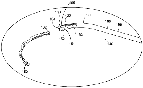
illustrated with dashed lines in Figure 5.
[000140] The length of major axis 60 and minor axis 62 can vary from patient
to patient. The
length of minor axis 62 is between one and thirty micrometers in most
patients. The length of
major axis 60 is between one hundred and fifty micrometers and three hundred
and fifty
micrometers in most patients.
[000141] With reference to Figure 5, Schlemm's canal SC comprises a first
major side 50, a
second major side 52, a first minor side 54, and a second minor side 56. In
the embodiment of
Figure 5, first major side 50 is longer than both first minor side 54 and
second minor side 56.
Also in the embodiment of Figure 5, second major side 52 is longer than both
first minor side 54
and second minor side 56.
[000142] Figure 6A is a perspective view showing a delivery system 100
including an ocular
implant 150 and a cannula 108 defining a passageway that is dimensioned to
slidingly receive
ocular implant 150. Delivery system 100 may be used to advance ocular implant
150 into a
target location in the eye of a patient. Examples of target locations that may
be suitable in some
applications include areas in and around Schlemm's canal, the trabecular
meshwork, the
- 16 -
CA 02859810 2014-06-18
WO 2013/096453
PCT/US2012/070626
suprachoroidal space, and the anterior chamber of the eye. Figure 6B is an
enlarged detail view
further illustrating ocular implant 150 and cannula 108 of delivery system
100.
[000143] Delivery system 100 of Figure 6A is capable of controlling the
advancement and
retraction of ocular implant 150 within cannula 108. Ocular implant 150 may be
placed in a
target location (e.g., Schlemm's canal) by advancing the ocular implant
through a distal opening
132 of cannula 108 while the distal opening is in fluid communication with
Schlemm's canal. In
the embodiment of Figure 6A, ocular implant 150 has been advanced through
distal opening 132
of cannula 108 for purposes of illustration.
[000144] Delivery system 100 of Figure 6A includes a housing 102, a sleeve
104, and an end
cap 110. A tracking wheel 106 extends through a wall of housing 102 in Figure
6A. Tracking
wheel 106 is part of a mechanism that is capable of advancing and retracting a
delivery tool 152
of delivery system 100. The delivery tool 152 extends through a distal opening
of cannula 108
of Figure 6B. Rotating the tracking wheel will cause delivery tool 152 to move
in an axial
direction along a passageway defined by cannula 108. The axial direction may
be in a distal
direction D or a proximal direction P.
[000145] In the embodiment of Figure 6A, housing 102 is configured to be
gripped with one
hand while providing control over the axial advancement and retraction of
ocular implant via
tracking wheel 106. The housing of delivery system 100 results in an
advantageous ergonomic
relationship of the fingers relative to the hand. This design provides a
configuration that will
allow a user, such as a physician, to stabilize the device using part of the
hand, while leaving the
middle or index finger free move independently from the remainder of the hand.
The middle or
index finger is free to move independently to rotate the wheel for advancing
and/or retract the
ocular implant.
[000146] Figure 6B is an enlarged detail view further illustrating ocular
implant 150 and a
cannula 108 of delivery system 100. Cannula 108 comprises a generally tubular
member 198
having proximal portion 140, a distal end 134, and a distal portion 144
extending between distal
end 134 and proximal portion 140. In the embodiment of Figure 6, distal
portion 144 is curved.
In some useful embodiments, distal portion 144 is dimensioned and configured
to be received in
the anterior chamber of the eye.
[000147] Figure 6B shows delivery tool 152 of delivery system 100 extending
through distal
opening 132 of cannula 108. Delivery tool 152 includes an interlocking portion
160 that is
configured to form a connection with a complementary interlocking portion 162
of ocular
implant 150, as explained in more detail below. In the embodiment of Figure 6,
rotating the
tracking wheel will cause delivery tool 152 and ocular implant 150 to move
along a path defined
by cannula 108. Cannula 108 is sized and configured so that the distal end of
cannula 108 can be
-17-
CA 02859810 2014-06-18
WO 2013/096453
PCT/US2012/070626
advanced through the trabecular meshwork of the eye and into Schlemm's canal.
Positioning
cannula 108 in this way places distal opening 132 in fluid communication with
Schlemm's canal.
Ocular implant 150 may be placed in Schlemm's canal by advancing the ocular
implant through
distal opening 132 of cannula 108 while the distal opening is in fluid
communication with
Schlemm's canal. The distal portion of the cannula may include a cutting
portion configured to
cut through the trabecular meshwork and the wall of Schlemm's canal, such as
by providing
distal end 134 with a sharp edge adapted to cut through such tissue.
[000148] Figure 7 is a perspective view further illustrating delivery system
100 shown in the
previous figure. In Figure 7, a portion of housing 102 has been removed for
purposes of
illustration. Delivery system 100 includes a delivery tool subassembly 170 and
a cannula
subassembly 180. Delivery tool subassembly 170 includes rotating rack gear 120
and a delivery
tool (not shown). In the embodiment of Figure 7, the delivery tool extends
into a passageway
defined by a cannula 108. Cannula 108 can be seen extending beyond sleeve 104
in Figure 7.
Cannula subassembly 180 includes cannula 108, a hub 172, and an extension tube
(not shown).
In the embodiment of Figure 7, the extension tube of cannula subassembly 180
is disposed inside
a lumen defined by rotating rack gear 120.
[000149] Delivery system 100 includes a mechanism 166 that controls the
movement of
delivery tool subassembly 170. Mechanism 166 includes a number of components
that are
located inside housing 102, including tracking wheel 106, an idler gear 122,
and the rotating rack
gear 120. In the embodiment of Figure 7, tracking wheel 106 and idler gear 122
are both
rotatably supported by housing 102. Gear teeth on tracking wheel 106 engage
gear teeth on idler
gear 122, which in turn engage gear teeth on the rotating rack gear 120.
Rotating tracking wheel
106 in a counter clockwise direction CCW causes idler gear 122 to rotate in a
clockwise
direction CW, which in turn causes the rotating rack gear 120 to move in a
distal direction D.
Rotating tracking wheel 106 in a clockwise direction CW causes idler gear 122
to rotate in a
counter clockwise direction CCW, which in turn causes the rotating rack gear
120 to move in a
proximal direction P. In other embodiments, the idler gear may be eliminated
from the device,
which would cause counter-clockwise movement of the tracking wheel to move the
rack gear
proximally.
[000150] In the embodiment of Figure 7, a sleeve 104 is fixed to cannula
subassembly 180.
Sleeve 104 may be rotated by the user to change the orientation of cannula 108
with respect to
housing 102. The sleeve 104 may include gripping features, such as grooves (as
shown), a
rubber coating, or other frictional surfaces to facilitate this use. In some
applications, correct
alignment between the cannula and iris is advantageous to ensure that the core
tube and/or ocular
implant is advanced at the correct trajectory relative to Schlemm's canal or
other anatomy in the
- 18 -
CA 02859810 2014-06-18
WO 2013/096453 PCT/US2012/070626
eye into which the ocular implant is to be implanted. The device is configured
in a manner that
keeps the ocular implant aligned within the device during rotation. Selected
groups of
components are keyed together to ensure that they rotate as a single body
while simultaneously
allowing axial movement of the ocular implant. In the embodiment of Figure 7,
cannula
subassembly 180 and delivery tool subassembly 170 rotate in unison with sleeve
104 relative to
housing 102.
[000151] In the embodiment of Figure 7, rotating rack gear 120 is configured
to rotate with
sleeve 104 while maintaining the ability to move axially in the distal and
proximal directions
before, during, and after rotation. As the rotating rack gear 120 moves
distally and/or
proximally, it causes corresponding movement of the delivery tool relative to
cannula 108. This
movement is transferred to ocular implant 150 when delivery tool 152 is
coupled to ocular
implant 150. Delivery tool subassembly 170 and cannula subassembly 180 engage
one another
in a keyed arrangement, as described in more detail below. This keyed
arrangement causes
delivery tool subassembly 170 and cannula subassembly 180 to maintain a
constant rotational
orientation relative to each other while, at the same time, allowing delivery
tool subassembly 170
to translate in a distal direction D and a proximal direction P relative to
cannula subassembly
180.
[000152] Figure 8 is an exploded view illustrating various elements of
delivery system 100.
Cannula subassembly 180 includes a hub 172 and an extension tube 174 that are
both fixed to
cannula 108. Extension tube 174 includes a shaped portion 175 that is
dimensioned and shaped
to fit within a shaped through hole 177 (shown in Figures 8A and 11) within by
rotating rack
gear 120. This keyed arrangement causes delivery tool subassembly 170 and
cannula
subassembly 180 to maintain a constant rotational orientation relative to each
other while, at the
same time, allowing delivery tool subassembly 170 to translate in a distal
direction D and a
proximal direction P relative to cannula subassembly 180.
[000153] In some embodiments, delivery tool 152 is formed from shape memory
material (such
as, e.g., nitinol), and at least a portion of delivery tool 152 assumes a
curved at-rest shape when
no external forces are acting on it. Delivery tool 152 can be urged to assume
a straightened
shape, for example, by inserting delivery tool 152 through a straight portion
of the passageway
defined by cannula 108. When the delivery tool is confined, such as within
cannula 108, the
interlocking portion can engage the complementary interlocking portion to join
the delivery tool
and ocular implant together, and allow the delivery tool and ocular implant to
move together
through the cannula 108, as described in more detail below.
[000154] Delivery system 100 also includes an 0-ring 126 disposed between
sleeve and 104
and housing 102. 0-ring 126 can provide friction and/or resistance between
sleeve 104 and
- 19 -
CA 02859810 2014-06-18
WO 2013/096453 PCT/US2012/070626
housing 102. This friction and/or resistance may be useful, for example, to
hold the sleeve 104
in a desired orientation. A noseplug 105 snaps into the distal end of the
delivery system.
[000155] Figure 9 is an exploded perspective view of delivery tool subassembly
170 shown in
the previous figure. Delivery tool subassembly 170 comprises a delivery tool
152, a rotating
rack gear 120, and a spacer 176. Delivery tool 152 includes a shaped proximal
portion 156, a
curved distal portion 153, a distal cannula engagement surface 161 and a
reduced diameter
portion 163 proximal to the distal cannula engagement surface 161. Spacer 176
is interposed
between rotating rack gear 120 and shaped proximal portion 156 of delivery
tool 152 to hold
delivery tool 152 and rotating rack gear 120 in a generally co-axial
arrangement when delivery
tool subassembly 170 is in an assembled state, as shown in Figure 11. Distal
cannula
engagement surface 161 is adapted to slide along an inside surface of the
cannula wall while the
delivery tool 152 is engaged to ocular implant 150. Curved distal portion 153
of delivery tool
152 has an at rest curve that is greater (i.e., has a smaller radius of
curvature) than the curved
portion 144 of cannula 108.
[000156] Figure 10 is an exploded perspective view of cannula subassembly 180.
Cannula
subassembly 180 comprises cannula 108, extension tube 174 and hub 172. In the
embodiment of
Figure 10, cannula 108 defines a passageway 138 that is dimensioned to
slidingly receive an
ocular implant and the delivery tool shown in the previous figure. At the same
time, extension
tube 174 of cannula subassembly 180 may be received inside a lumen defined by
the rotating
rack gear shown in the previous figure.
[000157] Extension tube 174 includes a shaped portion 175 that is dimensioned
and shaped to
fit within a shaped through hole defined by rotating rack gear 120, as shown
below in Figure 11.
This keyed arrangement causes delivery tool subassembly 170 and cannula
subassembly 180 to
maintain a constant rotational orientation relative to each other while, at
the same time, allowing
delivery tool subassembly 170 to translate in a distal direction D and a
proximal direction P
relative to cannula subassembly 180.
[000158] Figure 11 is a cross-sectional view showing an assembly including
delivery tool
subassembly 170 and cannula subassembly 180 discussed above. Delivery tool
subassembly 170
includes a delivery tool 152, a rotating rack gear 120 and a spacer 176. In
the cross-sectional
view of Figure 11, a shaped portion 156 of delivery tool 152 can be seen
extending into a slot
123 extending from a central portion 181 a through hole 177 formed in rotating
rack gear 120.
(Figure 8A shows an end view of rotating rack gear 120 and through hole 177.)
In the
embodiment of Figure 11, an interlocking portion 160 of delivery tool 152 is
disposed in angular
alignment with shaped portion 156. Spacer 176 is interposed between rotating
rack gear 120 and
delivery tool 152. In the exemplary embodiment of Figure 11, spacer 176 is
shaped and
- 20 -
CA 02859810 2014-06-18
WO 2013/096453
PCT/US2012/070626
dimensioned to hold delivery tool 152 and rotating rack gear in a generally co-
axial arrangement.
This arrangement creates an advantageous oriented relationship of interlocking
portion 160 with
respect to the distal opening 132 of cannula 108 and ensures that interlocking
portion 160 is
unimpeded and readily disengages itself from the implant when it exits and
flexes through distal
opening 132. In the exemplary embodiment of Figure 11, spacer 176 and rotating
rack gear 120
are fixed to each other at a weld joint 178. Weld joint 178 may be formed, for
example, using a
laser welding process.
[000159] Cannula subassembly 180 includes cannula 108, a hub 172, and an
extension tube
174. Extension tube 174 is disposed about cannula 108. Extension tube 174 and
cannula 108
may be fixed to one another, for example, using a laser spot welding process.
Hub 172 is fixed
to an outer surface portion of extension tube 174 in the embodiment of Figure
11. In Figure 11,
extension tube 174 of cannula subassembly 180 can be seen extending into a
shaped through-
hole defined by rotating rack gear 120 of delivery tool assembly 170.
[000160] In Figure 11, delivery tool 152 can be seen extending into a
passageway 138 defined
by a cannula 108 of cannula subassembly 180. Passageway 138 defined by cannula
108 is sized
to slidably enclose delivery tool 152 and an ocular implant that is coupled to
delivery tool 152.
Delivery tool 152 is configured to form a connection with the ocular implant,
so that distal
movement of the delivery tool can cause distal movement of the ocular implant
within cannula
108. Delivery tool 152 may be used to advance the ocular implant through a
distal opening 132
of cannula 108 in order to deliver the ocular implant into the eye. The
assembly of Figure 11
may be rotated by the user to change the orientation of the curved portion of
cannula 108 with
respect to the housing of the delivery system. The keyed relationship between
delivery tool
subassembly 170 and cannula subassembly 180 assures that the rotational
orientation between
cannula 108 and the ocular implant/delivery tool stays constant while at the
same time, allowing
ocular implant/delivery tool to translate in a distal direction D and a
proximal direction P relative
to cannula 108.
[000161] Figure 12 is a perspective view of a cannula 108 in accordance with
the present
detailed description. Cannula 108 of Figure 12 comprises a generally tubular
member 198
having a central axis 196. Generally tubular member 198 of Figure 12 comprises
a proximal
portion 140, a distal end 134, and a distal portion 144 extending between
distal end 134 and
proximal portion 140. A distal opening surface 142 surrounds a distal opening
132 extending
through the distal end and through a side wall of cannula 108. A beveled edge
165 is disposed at
the distal end of distal opening surface 142, extending from the distal end
134 to a proximal
extent 167 of beveled edge 165. Tubular member 198 defines distal opening 132,
a proximal
- 21 -
CA 02859810 2014-06-18
WO 2013/096453 PCT/US2012/070626
opening 136, and a passageway 138 extending between proximal opening 136 and
distal opening
132.
[000162] In the embodiment of Figure 12, proximal portion 140 of cannula 108
is substantially
straight, distal portion 144 of cannula 108 is curved, and central axis 196
defines a curvature
plane 148. Curvature plane 148 may be referred to as a plane of curvature.
Curvature plane 148
divides cannula 108 into a first portion PA and a second portion PB. In the
embodiment of
Figure 12, second portion PB is substantially a mirror image of first portion
PA. In Figure 12,
distal portion 144 is shown extending between distal end 134 and proximal
portion 140 with no
intervening elements. In the embodiment of Figure 12, distal portion 144 is
curved along its
entire length.
[000163] A method in accordance with this detailed description may include the
step of
advancing the distal end 134 of cannula 108 through the cornea of a human eye
so that distal end
134 is disposed in the anterior chamber of the eye. Cannula 108 may then be
used to access
Schlemm's canal of the eye, for example, by piercing the wall of Schlemm's
canal with the distal
end 134 of cannula 108. The beveled edge 165 may be inserted into Schlemm's
canal to place at
least part of distal opening 132 of cannula 108 in communication with
Schlemm's canal, as
discussed in more detail below. The ocular implant may be advanced out of a
distal port of the
cannula and into Schlemm's canal.
[000164] In the embodiment of Figure 12, distal portion 144 of cannula 108
defines a trough
154. In some useful embodiments, trough 154 is configured to receive the
entire external cross
section of an ocular implant as the ocular implant is being advanced into
Schlemm's canal.
When this is the case, trough 154 may have a depth dimension that is deeper
than a width of the
ocular implant. This cannula configuration advantageously prevents the ocular
implant from
intersecting the layers of the trabecular meshwork as the ocular implant is
advanced into
Schlemm's canal. Trough 154 may also be configured to allow the proximal
portion of the
ocular implant to be released from the delivery tool, as discussed below.
[000165] Figure 13 is a perspective view of an assembly including cannula 108
shown in the
previous figure. For purposes of illustration, cannula 108 is cross-
sectionally illustrated in
Figure 13. In Figure 13, an ocular implant 150 can be seen resting in a
passageway 138 defined
by cannula 108. With reference to Figure 13, it will be appreciated that
distal portion 144 of
cannula 108 is curved so that central axis 196 of cannula 108 defines a
curvature plane 148.
With reference to Figure 13, it will be appreciated that curvature plane 148
divides cannula 108
into a first portion and a second portion PB. Only second portion PB of
cannula 108 is shown in
the illustrative embodiment of Figure 13.
- 22 -
CA 02859810 2014-06-18
WO 2013/096453
PCT/US2012/070626
[000166] Figure 14 is a stylized perspective view including the assembly shown
in the previous
figure. In the embodiment of Figure 14, a distal portion of cannula 108 is
shown extending
through the wall of Schlemm's canal SC. The distal tip of cannula 108 may
include a sharp
portion configured for cutting and/or pierced the trabecular meshwork and the
wall of
Schlemm's canal so that the passageway defined by the cannula can be placed in
fluid
communication with the lumen defined by Schlemm's canal. With the passageway
of the
cannula placed in fluid communication with the lumen of Schlemm's canal,
ocular implant 150
can be advanced out of the distal opening of the cannula and into Schlemm's
canal. In Figure
14, a distal portion of ocular implant 150 can be seen through distal opening
132 of cannula 108.
[000167] For purposes of illustration, a hypothetical window W is cut through
the wall of
cannula 108 in Figure 14. An interlocking portion 160 of a delivery tool 152
and a
complementary interlocking portion 162 of ocular implant 150 are visible
through window W.
In the embodiment of Figure 14, interlocking portion 160 of delivery tool 152
and
complementary interlocking portion 162 of ocular implant 150 are engaging each
other so that a
proximal end 149 of ocular implant 150 is proximal to the distal end 151 of
delivery tool 152.
Surface 161 of delivery tool 152 rests against the wall of cannula 108 to
prevent interlocking
portion 160 of delivery tool 152 and complementary interlocking portion 162 of
ocular implant
150 from disengaging one another. When they are connected in this fashion,
delivery tool 152
and ocular implant 150 move together as the delivery tool is advanced and
retracted relative to
cannula 108 by the delivery system mechanism.
[000168] Figure 15 is an enlarged perspective view showing a portion of
cannula 108 shown in
the previous figure. In some useful embodiments, cannula 108 is curved to
achieve substantially
tangential entry into Schlemm's canal SC. In the embodiment of Figure 15,
cannula 108 is
contacting an outer major wall of Schlemm's canal SC at a point of tangency
PT. Also in the
embodiment of Figure 15, a curved distal portion of cannula 108 is dimensioned
to be disposed
within the anterior chamber of the eye.
[000169] As shown in Figure 15, the distal tip 134 and beveled edge of the
cannula 108 have
been inserted into Schlemm's canal up to the proximal extent 167 of beveled
edge 165. In this
position, ocular implant 150 can be seen extending into trough 154. In some
useful
embodiments, the ocular implant has a radius of curvature that is larger than
the radius of
curvature of the cannula. This arrangement ensures that the ocular implant
will track along
trough 154 as the ocular implant is urged in a distal direction by delivery
system 100.
[000170] Figure 16 is an additional perspective view showing ocular implant
150 and cannula
108 shown in the previous figure. By comparing Figure 16 with the previous
figure, it will be
appreciated that ocular implant 150 has been advanced in a distal direction D
while cannula 108
- 23 -
CA 02859810 2014-06-18
WO 2013/096453
PCT/US2012/070626
has remained stationary so that a distal portion of ocular implant 150 is
disposed inside
Schlemm's canal SC. Trough 154 opens into an elongate opening 132 defined by
edge 142 at
the distal portion of cannula 108. In the embodiment of Figure 16, the
elongate opening defined
by the cannula provides direct visualization of the ocular implant as it is
advanced into
Schlemm's canal. A configuration allowing direct visualization of the ocular
implant has a
number of clinical advantages. During a medical procedure, it is often
difficult to monitor the
progress of the implant by viewing the implant through the trabecular
meshwork. For example,
blood reflux may push blood into Schlemm's canal obstructing a physician's
view the portion of
the implant that has entered Schlemm's canal. With reference to Figure 16,
ocular implant 150
tracks along trough 154 as it is advanced distally along cannula 108. The
trough opening allows
the physician to monitor the progress of the implant by viewing the implant
structures as they
advance through the trough prior to entering Schlemm's canal. The trough
opening also allows
the physician to identify the position of the proximal end of the ocular
implant with respect to the
incision made by the cannula to access Schlemm's canal.
[000171] Figure 17 is an additional stylized perspective view showing ocular
implant 150 and
cannula 108. In the embodiment of Figure 17, the interlocking portions 160 and
162 of the
delivery tool 152 and ocular implant 150, respectively, can be seen entering
the distal opening
132 defined by cannula 108. As shown, ocular implant 150 has been advanced in
a distal
direction D (relative to the embodiment shown in the previous figure) so that
more of ocular
implant 150 is disposed inside Schlemm's canal SC. Surface 161 opposite
interlocking portion
160 of delivery tool 152 still rests against the inner wall of cannula 108 to
keep the delivery tool
interlocked with ocular implant 150.
[000172] Figure 18 is an additional stylized perspective view showing ocular
implant 150 and
cannula 108. As shown in Figure 18, the ocular implant 150 and delivery tool
152 have
advanced further distally so that delivery tool surface 161 and part of the
reduced diameter
portion 163 have now passed into opening 132, thereby permitting the delivery
tool curved
portion 153 to move toward its curved at-rest shape so that the delivery tool
engagement surface
160 disengages and moves away from its complementary engagement surface 162 on
the ocular
implant 150.
[000173] In some useful embodiments, the delivery tool may be colored to
provide visual
differentiation from the implant. After the disengaging from the ocular
implant, cannula 108 and
delivery tool 152 can be withdrawn from Schlemm's canal SC leaving the ocular
implant 150 in
the fully deployed position shown in Figure 18. After delivery of ocular
implant 150 is
complete, the delivery tool and the cannula may be removed from the eye,
leaving at least a
distal portion of the ocular implant in Schlemm's canal.
- 24 -
CA 02859810 2014-06-18
WO 2013/096453 PCT/US2012/070626
[000174] Figure 19 is a perspective view of Schlemm's canal SC after the
cannula (seen in the
previous figure) has been withdrawn leaving an inlet portion of ocular implant
150 in the anterior
chamber of the eye and the remainder of ocular implant 150 in Schlemm's canal.
The presence
of ocular implant 150 in Schlemm's canal may facilitate the flow of aqueous
humor out of the
anterior chamber. This flow may include axial flow along Schlemm's canal, flow
from the
anterior chamber into Schlemm's canal, and flow leaving Schlemm's canal via
outlets
communicating with Schlemm's canal. When in place within the eye, ocular
implant 150 will
support the trabecular meshwork and Schlemm's canal tissue and will provide
for improved
communication between the anterior chamber and Schlemm's canal (via the
trabecular
meshwork) and between pockets or compartments along Schlemm's canal.
[000175] Figures 20A - Figure 20H are a series of stylized plan views
illustrating example
methods in accordance with this detailed description and associated apparatus
used while
performing those methods. In Figure 20A, a distal portion of cannula 108 is
shown extending
through the wall of Schlemm's canal SC. In the embodiment of Figure 20A,
cannula 108
includes a sharp portion at its distal end 134 configured for cutting and/or
pierced the trabecular
meshwork and the wall of Schlemm's canal SC. In the embodiment of Figure 20A,
the distal
end of cannula 108 has been advanced through the trabecular meshwork and the
wall of
Schlemm's canal SC and a passageway defined by cannula 108 has been placed in
fluid
communication with the lumen defined by Schlemm's canal SC.
[000176] Figure 20B is an additional stylized plan view showing cannula 108
shown in the
previous figure. In the embodiment of Figure 20B, an ocular implant 150 has
been advanced out
of a distal opening of cannula 108 and into Schlemm's canal SC. In Figure 20B,
a distal portion
of ocular implant 150 is shown residing in a lumen defined by Schlemm's canal.
[000177] Figure 20C is an additional stylized plan view showing ocular implant
150 and
cannula 108. In the embodiment of Figure 20C, an interlocking portion 160 of
delivery tool 152
and complementary interlocking portion 162 of ocular implant 150 are both
disposed near a
trough portion of cannula 108. Ocular implant 150 has been advanced in a
distal direction D
(relative to the embodiment shown in the previous figure) so that more of
ocular implant 150 is
disposed inside Schlemm's canal SC. In Figure 20C, ocular implant is shown
residing in a fully
deployed position. As shown in Figure 20C, interlocking portion 160 of
delivery tool 152 has
disengaged from complementary interlocking portion 162 of ocular implant 150.
[000178] In the embodiment of Figure 20C, distal opening 132 defined by
cannula 108 is
shaped and dimensioned so as to allow interlocking portion 160 of delivery
tool 152 to extend
therethrough when ocular implant 150 reaches the fully deployed position shown
in Figure 20C.
When surface 161 has entered opening 132, a distal portion of delivery tool
152 is free to flex
- 25-
CA 02859810 2014-06-18
WO 2013/096453
PCT/US2012/070626
radially inward toward a curved, at-rest shape extending through distal
opening 132 when ocular
implant 150 reaches the fully deployed position shown in Figure 20C to
disengage from the
ocular implant.
[000179] Figure 20D is a plan view of Schlemm's canal SC after cannula 108 has
been moved
away from ocular implant 150. After moving cannula 108 away from ocular
implant 150, a
physician may visually inspect the present location of the ocular implant to
determine whether
that location is acceptable. If the physician determines that the present
location is unacceptable,
the physician may use the systems and methods described herein to recapture
and reposition the
ocular implant. The figures described below illustrate exemplary methods and
apparatus for
recapturing and repositioning the ocular implant.
[000180] In the embodiment of Figure 20E, cannula 108 has been positioned so
that the
complementary interlocking portion 162 of ocular implant 150 is disposed
between cannula 108
and the interlocking portion 160 of delivery tool 152. Further distal movement
of cannula 108
will cause delivery tool surface 161 to re-engage with the inner wall of
cannula 108, thereby
moving the interlocking portion 160 of the delivery tool into re-engagement
with the ocular
implant. The delivery tool and ocular implant can thereafter be moved
proximally, possibly
together with the cannula, to reposition the implant for subsequent
redeployment.
[000181] Figure 20F is an additional stylized plan view showing ocular implant
150 and
cannula 108 shown in the previous figure. By comparing Figure 20F with the
previous figure, it
will be appreciated that delivery tool 152 and ocular implant 150 have been
moved in a proximal
direction P so that a portion of ocular implant 150 has been withdrawn from
Schlemm's canal
SC. In the embodiment of Figure 20F, the complementary interlocking portion of
ocular implant
150 and the interlocking portion of delivery tool 152 have both been drawn
into the passageway
defined by cannula 108. Also in the embodiment of Figure 20F, the side wall of
cannula 108 is
holding the distal portion of delivery tool 152 in a deformed shape with the
interlocking portion
of delivery tool 152 engaging the complementary interlocking portion of ocular
implant 150.
[000182] Figure 20G is an additional stylized plan view showing ocular implant
150 and
cannula 108 shown in the previous figure. In the embodiment of Figure 20G,
ocular implant 150
has been advanced out of a distal opening of cannula 108 and into Schlemm's
canal SC. In
Figure 20G, a distal part of ocular implant 150 is shown residing in a lumen
defined by
Schlemm's canal. In the embodiment of Figure 20G, interlocking portion 160 of
delivery tool
152 and complementary interlocking portion 162 of ocular implant 150 are both
once again
located near a trough portion of cannula 108. In Figure 20G, ocular implant is
shown residing in
a second fully deployed position. In the embodiment of Figure 20G, the
delivery tool 152 has
once again disengaged from ocular implant 150 by permitting interlocking
portion 160 of
- 26 -
CA 02859810 2014-06-18
WO 2013/096453 PCT/US2012/070626
delivery tool 152 to move away from complementary interlocking portion 162 of
ocular implant
150
[000183] Figure 20H is a stylized plan view showing ocular implant 150 and
Schlemm's canal
SC after the cannula (seen in the previous figure) has been withdrawn leaving
an inlet portion of
ocular implant 150 in the anterior chamber of the eye and the remainder of
ocular implant 150 in
Schlemm's canal. When in place within the eye, ocular implant 150 will support
the trabecular
meshwork and Schlemm's canal tissue and will provide for improved
communication between
the anterior chamber and Schlemm's canal (via the trabecular meshwork) and
between pockets
or compartments along Schlemm's canal. Accordingly, the presence of ocular
implant 150 in
Schlemm's canal will facilitate the flow of aqueous humor out of the anterior
chamber.
[000184] With reference to the figures described above, it will be appreciated
that methods in
accordance with the present detailed description may be used to position at
least .a distal portion
of an implant in Schlemm's canal of an eye. In some cases, a proximal inlet
portion of the ocular
implant may be left in the anterior chamber. An exemplary method in accordance
with the
present detailed description may include the step of advancing a distal end of
a cannula through a
cornea of the eye so that a distal portion of the cannula is disposed in the
anterior chamber of the
eye. The cannula may be used to access Schlemm's canal, for example, by
cutting and/or
piercing the wall of Schlemm's canal with a distal portion of the cannula. A
distal opening of
the cannula may be placed in fluid communication with Schlemm's canal. The
distal end of the
ocular implant may be advanced through the distal opening of the cannula and
into Schlemm's
canal.
[000185] After delivering an ocular implant into Schlemm's canal, a physician
may visually
inspect the present location of the ocular implant to determine whether that
location is
acceptable. If the physician determines that the present location is
unacceptable, the physician
may use the systems and methods described herein to recapture and redeliver
the ocular implant.
Recapturing and redelivering the ocular implant may include the steps of
forming a second
connection between the delivery tool and the ocular implant and moving the
delivery tool and the
ocular implant in a proximal direction so that at least a portion of the
ocular implant is
withdrawn from Schlemm's canal. A distal part of the ocular implant may be
advanced into
Schlemm's canal while the ocular implant is coupled to the delivery tool at
the second
connection. The second connection may be selectively broken to release the
ocular implant from
the delivery system while the distal part of the ocular implant is disposed in
Schlemm's canal.
[000186] Figure 21 is a perspective view showing a delivery tool subassembly
370 that may be
part of a delivery system (e.g., delivery system 100 shown in Figure 8).
Delivery tool
subassembly 370 of Figure 21 comprises a rotating rack gear 320 that is fixed
to a delivery tool
-27-
CA 02859810 2014-06-18
WO 2013/096453 PCT/US2012/070626
352. Delivery tool 352 includes an interlocking portion 360 and a curved
distal portion 353.
Curved distal portion 353 of delivery tool 352 is biased to assume the curved
at-rest shape shown
in Figure 21 when no external forces are acting on it. Curved distal portion
353 of delivery tool
352 may be urged to assume a straightened shape, for example, when it is
disposed in a straight
portion of a passageway defined by a cannula. Optional cut-outs 351 may be
formed in the wall
of delivery tool 352 to reduce friction during tool advancement by reducing
the bending force.
The cannula wall may also hold interlocking portion 360 of delivery tool 352
into engagement
with a complementary interlocking portion of an ocular implant to form a
mechanically
interlocking connection.
[000187] Figure 22A is a stylized plan view showing delivery tool 352 shown in
the previous
figure. In the embodiment of Figure 22A, delivery tool 352 is extending into a
passageway 338
defined by a cannula 308. A distal portion of cannula 308 defines a trough 354
that
communicates with the passageway 338 defined by the wall of cannula 308.
Trough 354 opens
out the distal end of cannula 308. Trough 354 also opens into an elongate
opening 332 defined
by the edge 342 of the cannula wall.
[000188] In Figure 22A, cannula 308 is illustrated in partial cross section.
Interlocking portion
360 of delivery tool 352 and a complementary interlocking portion 362 of an
ocular implant 350
are visible in Figure 22A. In the embodiment of Figure 22A, interlocking
portion 360 of
delivery tool 352 and complementary interlocking portion 362 of ocular implant
350 are
engaging each other to form a mechanically interlocking connection such that
the implant's
interlocking portion 362 is proximal to the delivery tool's interlocking
portion 360. The delivery
tool 352 and ocular implant 350 may be selectively disengaged when
interlocking portion 360 of
delivery tool 352 is allowed to move away from and disengage complementary
interlocking
portion 362 of ocular implant 350. In the embodiment of Figure 22, the wall of
cannula 308 is
preventing interlocking portion 360 of delivery tool 352 from moving away from
and
disengaging complementary interlocking portion 362 of ocular implant 350. A
surface 363 of
delivery tool 352 can be seen contacting the wall of cannula 308 at a point S
in Figure 22.
[000189] In Figure 22A, interlocking portion 360 of delivery tool 352 is shown
disposed within
cannula passageway 338 at a location proximal of trough 354 and distal opening
332. In some
useful embodiments, opening 332 is dimensioned and positioned such that, when
the ocular
implant reaches a predefined location along the passageway, the distal portion
of delivery tool
352 will be free to move toward a curved at-rest shape. When the delivery tool
assumes a curved
shape, the interlocking portion of the delivery tool moves away from and
disengages the
complementary interlocking portion of the ocular implant. In this way,
delivery tool 352 and
- 28 -
CA 02859810 2014-06-18
WO 2013/096453 PCT/US2012/070626
ocular implant 350 may be selectively disengaged as delivery tool 352 is moved
distally along
the passageway defined by the cannula from a starting location proximal of
opening 332.
[000190] Figure 22B is an additional stylized plan view illustrating cannula
308, ocular implant
350, and delivery tool 352 shown in the previous figure. By comparing Figure
22B with Figure
22A, it will be appreciated that delivery tool 352 has been advanced in a
distal direction D so
that delivery tool 352 is extending through opening 332 and ocular implant 350
is outside of
cannula passageway 338. In the embodiment of Figure 22B, interlocking portion
360 has moved
away from complementary interlocking portion 362 and ocular implant 350 and
delivery tool
352 have disengaged.
[000191] Figure 23 is a stylized plan view showing a delivery system 500
including an ocular
implant 550 disposed in a passageway 538 defined by a cannula 508. Figure 23
includes an
enlarged detail view V illustrating a portion of cannula 508. For purposes of
illustration, a
hypothetical window W is cut through the wall of cannula 508 in Figure 23. An
interlocking
portion 560 of a delivery tool 552 and a complementary interlocking portion
562 of ocular
implant 550 are visible through window W. In the embodiment of Figure 23,
interlocking
portion 560 of delivery tool 552 and complementary interlocking portion 562 of
ocular implant
550 are engaging each other to form a mechanically interlocking connection.
When delivery tool
552 is confined, such as within cannula passageway 538, it can be held in
mechanically
interlocking engagement with ocular implant 550 so that these elements move
together through
passageway 538 of cannula 508. An optional ring 561 proximal to interlocking
portion 560 and
to the proximal end of implant 550 maintains the spacing between interlocking
portion 560 and
interlocking portion 562 so that they can be more easily disengaged. The wall
of cannula 508
prevents interlocking portion 560 of delivery tool 552 and complementary
interlocking portion
562 of ocular implant 550 from disengaging one another in the embodiment of
Figure 23. A
surface 565 of delivery tool 552 can be seen contacting the wall of cannula
508 at a point S in
Figure 23.
[000192] Delivery system 500 of Figure 23 may be used to advance ocular
implant 550 into a
target location in the eye of a patient. Delivery system 500 includes a
housing 502 and a
tracking wheel 506 that can be seen extending through the wall of housing 502
in Figure 23.
Tracking wheel 506 is part of a mechanism that is capable of advancing and
retracting delivery
tool 552 of delivery system 500. Rotating tracking wheel 506 will cause
delivery tool 552 to
move in an axial direction along a passageway 538 defined by cannula 508. The
axial direction
may be in a distal direction D or a proximal direction P. Ocular implant 550
moves along with
delivery tool 552 as it is advanced and retracted relative to cannula 508 by
the delivery system
mechanism.
- 29 -
CA 02859810 2014-06-18
WO 2013/096453 PCT/US2012/070626
[000193] In the embodiment of Figure 23, housing 502 is configured to be
gripped with one
hand while providing control over the axial advancement and retraction of the
ocular implant via
tracking wheel 506. The design of housing 502 results in an advantageous
ergonomic
relationship of the fingers relative to the hand. This design provides a
configuration that will
allow a user, such as a physician, to stabilize the device using part of the
hand, while leaving the
middle or index finger free move independently from the remainder of the hand.
The middle or
index finger is free to move independently to rotate tracking wheel 506 of
delivery system 500
for advancing and/or retracting delivery tool 552.
[000194] Figure 24A is a stylized plan view further illustrating cannula 508
shown in the
previous figure. A distal portion of cannula 508 defines a trough 554 that
communicates with a
passageway 538 defined by the wall of cannula 508. Trough 554 opens out the
distal end of
cannula 508. Trough 554 also opens into an elongate opening 532 defined by the
edge 542 of
the cannula wall. An ocular implant 550 and a portion of a delivery tool 552
are disposed within
cannula passageway 538. A distal portion of delivery tool 552 is biased to
assume a curved at-
rest shape when no external forces are acting on it. In the embodiment of
Figure 24A, the distal
portion of delivery tool 552 is disposed in a straight portion of the cannula
passageway 538 so
that it is urged to assume a straightened shape.
[000195] Figure 24B is an additional stylized plan view illustrating cannula
508, ocular implant
550, and delivery tool 552 shown in the previous figure. In figure 24B,
delivery tool 552 is
shown extending through opening 532 and ocular implant 550 is shown in a
location outside of
cannula passageway 538. In Figure 24B, a gap can be seen between interlocking
portion 560 of
delivery tool 552 and a complementary interlocking portion 562 of ocular
implant 550 in figure
24B. Accordingly, it will be appreciated that ocular implant 550 and delivery
tool 552 have
disengaged. In the embodiment of Figure 24B, the distal portion of delivery
tool 552 has flexed
through distal opening 532 as it has assumed a curved shape.
[000196] Reference is now made to both Figure 24A and Figure 24B which may be
collectively referred to as Figure 24. In the embodiment of Figure 24A, the
distal end of delivery
tool 552 is disposed within cannula passageway 538 at a location proximal of
trough 554 and
distal opening 532. In the embodiment of Figure 24B, delivery tool 552 has
been advanced in a
distal direction D so that delivery tool 552 is extending through opening 532.
Opening 532 is
dimensioned and positioned such that, when the ocular implant reaches a
predefined location
along the passageway, the distal portion of delivery tool 552 will be free to
move toward a
curved at-rest shape. When the delivery tool assumes a curved shape, the
interlocking portion of
the delivery tool moves away from and disengages the complementary
interlocking portion of
the ocular implant. In this way, delivery tool 552 and ocular implant 550 may
be selectively
-30-
CA 02859810 2014-06-18
WO 2013/096453 PCT/US2012/070626
disengaged as delivery tool 552 is moved distally along passageway 538 from
the position
shown in Figure 24A to the position shown in Figure 24B.
[000197] Figure 25A is a perspective view showing a delivery tool subassembly
770 that may
be part of a delivery system (e.g., delivery system 100 shown in Figure 8).
Delivery tool
subassembly 770 of Figure 25A comprises a rotating rack gear 720 that is fixed
to a delivery tool
752 formed as a flat ribbon. Figure 25B is enlarged perspective view showing a
distal portion of
delivery tool 752. Figure 25A and Figure 25B may be collectively referred to
as Figure 25.
Delivery tool 752 of Figure 25 includes an interlocking portion 760 and a
curved distal portion
753. Curved distal portion 753 of delivery tool 752 is biased to assume the
curved at-rest shape
shown in Figure 25 when no external forces are acting on it. Curved distal
portion 753 of
delivery tool 752 may be urged to assume a straightened shape, for example,
when it is disposed
in a straight portion of a passageway defined by a cannula. The cannula wall
may also hold
interlocking portion 760 of delivery tool 752 into engagement with a
complementary
interlocking portion of an ocular implant to form a mechanically interlocking
connection.
[000198] Figure 26A is a stylized perspective view showing a cannula 708
having a distal
portion positioned so as to extend through the wall of Schlemm's canal SC. The
distal tip of
cannula 708 may include a sharp portion configured for cutting and/or pierced
the trabecular
meshwork and the wall of Schlemm's canal so that a passageway 738 defined by
the cannula can
be placed in fluid communication with the lumen defined by Schlemm's canal.
With the
passageway of the cannula placed in fluid communication with the lumen of
Schlemm's canal,
an ocular implant 750 can be advanced out of the distal opening of the cannula
and into
Schlemm's canal. Insertion of the ocular implant into Schlemm's canal may
facilitate the flow
of aqueous humor out of the anterior chamber of the eye.
[000199] In Figure 26A, delivery tool 752 is shown extending out of passageway
738 defined
by a cannula 708. A surface 767 of delivery tool 752 rests against an inner
wall surface of
cannula 708 to keep delivery tool 752 interlocked with ocular implant 750. A
distal portion of
cannula 708 defines a trough 754 that communicates with passageway 738 defined
by the
cannula wall. Trough 754 opens out the distal end of cannula 708. Trough 754
also opens into
an elongate opening 732 defined by the edge 742 of the cannula wall.
[000200] Figure 26B is an additional perspective view showing ocular implant
750 and cannula
708 shown in the previous figure. By comparing Figure 26B with the previous
figure, it will be
appreciated that ocular implant 750 and delivery tool 752 have advanced
further distally so that
part of delivery tool surface 767 and part of distal curved portion 753 have
now passed through
opening 732, thereby permitting the distal tool portion to move toward its
curved at-rest shape so
-31-
CA 02859810 2014-06-18
WO 2013/096453
PCT/US2012/070626
that the delivery tool interlocking portion 760 disengages and moves away from
its
complementary interlocking portion 762 on the ocular implant 750.
[000201] Reference is now made to both Figure 26A and Figure 26B which may be
collectively referred to as Figure 26. In the embodiment of Figure 26, ocular
implant 750 tracks
along trough 754 as it is advanced distally along cannula 708. The trough
opening allows the
physician to monitor the progress of the implant by viewing the implant
structures as they
advance through the trough prior to entering Schlemm's canal. The trough
opening also allows
the physician to identify the position of the proximal end of the ocular
implant with respect to the
incision made by the cannula to access Schlemm's canal. Additionally, the
trough opening
allows the physician to see when the delivery tool is going to release the
implant to monitor
when he or she will lose the ability to retract the implant.
[000202] Figure 27A is a top view showing a cannula 108 and a delivery tool
152. Cannula
108 and delivery tool 152 may form part of a delivery system for delivering an
ocular implant
150 in the eye of a patient. The delivery tool 152 and/or the ocular implant
can comprise an
elastic or bendable material configured to assume a pre-determined shape, such
as a shape
memory material, for example. As shown in Figure 27A, body 182 of cannula 108
comprises a
first side 183 and a second side 184 that extend along opposite sides of a
longitudinal center axis
196. Longitudinal center axis 196 includes a curved portion 185 having a
radius RA. In Figure
27A, radius RA can be seen extending from a curvature center point CP to
longitudinal center
axis 196.
[000203] Delivery tool 152 comprises a proximal portion 153, a distal
interlocking portion 160,
and a ribbon portion 163 that extends between proximal portion 153 and distal
interlocking
portion 160. In the embodiment of Figure 27A, no external forces are acting on
delivery tool
152 and ribbon portion 163 is free to assume a predetermined or unbiased and
undeformed
shape. In some embodiments, the predetermined shape can comprise a curved
resting shape.
With reference to Figure 27A, delivery tool 152 has a radius of curvature RC
when it is free to
assume the undeformed shape. Radius RC can be seen extending from curvature
center point CP
to a longitudinal axis LC of delivery tool 152 in Figure 27A. With reference
to Figure 27A, the
radius RC of delivery tool 152 is smaller than the radius RA of cannula 108.
As will be
described in more detail below, the ocular implant 150 can be configured to
engage the delivery
tool 150 within a passageway of the cannula. In some useful embodiments, a
trough portion 189
of distal opening 132 of cannula 108 is dimensioned and positioned such that,
when ocular
implant 150 reaches a predefined location along the passageway of the cannula,
the distal portion
of delivery tool 152 will be free to move toward a curved at-rest shape to
release the ocular
implant.
- 32 -
CA 02859810 2014-06-18
WO 2013/096453 PCT/US2012/070626
[000204] In the embodiment of Figure 27A, no external forces are acting on the
ocular implant
and ocular implant 150 is free to assume an undeformed shape. With reference
to Figure 27A,
ocular implant 150 has a radius of curvature RB when it is free to assume the
undeformed shape.
Radius RB of ocular implant 150 can be seen extending from a curvature center
point CP to a
longitudinal axis LA of ocular implant 150 in Figure 27A. Ocular implant 150
may comprise,
for example, the ocular implant disclosed in US Patent Publ. No. 2011/0009958.
[000205] With reference to Figure 27A, the radius RA of cannula 108 is smaller
than the radius
RB of ocular implant 150. This arrangement allows the elastic behavior of the
ocular implant to
bias the ocular implant against an inner surface of cannula 108 as the distal
end of ocular implant
150 travels through trough 186 of the cannula. Biasing the ocular implant
against the inner
surface of the trough helps assure that the distal end of the ocular implant
travels between the
inner surface of the trough and tissue covering a portion of the distal
opening 132. This
arrangement also helps assure that the distal end of the ocular implant
follows the path defined
by trough 186 as it is advanced in a distal direction through the cannula.
[000206] Ocular implant 150, delivery tool 152 and cannula 108 may be
fabricated from
various biocompatible materials possessing the necessary structural and
mechanical attributes.
Both metallic and non-metallic materials may be suitable. Examples of metallic
materials
include stainless steel, tantalum, gold, titanium, and nickel-titanium alloys
known in the art as
Nitinol. Nitinol is commercially available from Memry Technologies
(Brookfield, Conn.), TiNi
Alloy Company (San Leandro, Calif.), and Shape Memory Applications (Sunnyvale,
Calif.).
Nitinol is one advantageous material for ocular implant 150 and delivery tool
152 due to its
super elastic properties. Stainless Steel can be used for cannula 108 due to
its mechanical
strength and ability to maintain its shape and cause ocular implant 150 and
deliver tool 152 to
conform within it.
[000207] Figure 27B is a cross-sectional view of cannula 108 taken along
section line B-B
shown in Figure 27A. As shown in Figure 27B, cannula 108 has an inner diameter
Dl. Cannula
108 of Figure 27B defines a lumen 187. In some embodiments, the cannula
defines a trough and
a lumen that define a pathway extending from a location outside of the eye to
a location inside
Schlemm's canal when a distal point of the cannula is inside Schlemm's canal
of the eye. An
ocular implant can be delivered into Schlemm's canal by advancing the ocular
implant along the
pathway defined by the lumen and the trough.
[000208] Figure 27C, Figure 27D and Figure 27E are cross-sectional views of
delivery tool 152
shown in the previous figure. These section views correspond to section lines
shown in Figure
27A. More particularly, Figure 27C, Figure 27D and Figure 27E correspond to
section line C-C,
D-D, and E-E, respectively. Figures 27A through 27 F may be collectively
referred to as Figure
- 33 -
CA 02859810 2014-06-18
WO 2013/096453 PCT/US2012/070626
27. In the embodiment of Figure 27, proximal portion 153, distal interlocking
portion 160, and
ribbon portion 163 of delivery tool 152 can all have an outer diameter D2. In
some useful
embodiments, delivery tool 152 is fabricated by removing material from a wire
having a
generally cylindrical shape. As shown in Figure 27D, ribbon portion 163 of
delivery tool 152
has a thickness T that extends between a first major side 112 of ribbon
portion 163 and a second
major side 114 of ribbon portion 163.
[000209] In some embodiments, the outer diameter of the ribbon portion can be
only slightly
smaller than the inner diameter of the cannula so that the ribbon portion
tracks along the widest
part of the cannula lumen and so that support provided by the cannula wall
makes it less likely
that ribbon portion will buckle. The outer diameter of the ribbon portion may
be designed to be
smaller than the inner diameter of the cannula by a selected clearance value.
In some useful
embodiments, the clearance value is less than two times the wall thickness of
the ocular implant.
In some embodiments, a clearance value can be between about 0.0005 inches and
about 0.0010
inches.
[000210] Figure 27F is a cross-sectional view of an ocular implant 150 taken
along section line
F-F shown in Figure 27A. With reference to Figure 27, it will be appreciated
that ocular implant
150 and distal interlocking portion 160 of delivery tool 152 both have an
outer diameter D2. In
some useful embodiments, the ocular implant and the distal interlocking
portion of the delivery
tool have an outer diameter designed to provide a carefully selected clearance
between those
elements and the inner diameter of the cannula. The clearance is large enough
to allow the
delivery tool and the ocular implant to slide along the lumen of the cannula.
At the same time,
the clearance is small enough to prevent unintentional release of the ocular
implant, for example,
when the complimentary interlocking portion of the ocular implant climbs over
the interlocking
portion of the delivery tool. The clearance is also small enough to reduce the
likelihood that the
ocular implant will become jammed, for example, when the wall of the ocular
implant becomes
lodged between the delivery tool and the inner diameter of the cannula. In
some embodiments,
the clearance value is less than two times the wall thickness of the ocular
implant.
[000211] Figure 27G is an isometric view showing a distal portion of delivery
tool 152.
Delivery tool 152 comprises a proximal portion (not shown), a distal
interlocking portion 160,
and a ribbon portion 163 that extends between the proximal portion and distal
interlocking
portion 160. In the embodiment of Figure 27A, no external forces are acting on
delivery tool
152. As shown in Figure 27G, ribbon portion 163 of delivery tool 152 can be
biased to assume a
curved resting shape when no external forces are acting on it (e.g., external
forces from an
interior surface of the cannula).
- 34 -
CA 02859810 2014-06-18
WO 2013/096453
PCT/US2012/070626
[000212] Ribbon portion 163 of delivery tool 152 has an outer diameter D2 and
a thickness T.
As shown in Figure 27G, thickness T extends between a first major side 112 of
ribbon portion
163 and a second major side 114 of ribbon portion 163. With reference to
Figure 27G, it will be
appreciated that outer diameter D2 is greater than thickness T. In some useful
embodiments, an
aspect ratio of outer diameter to thickness is also selected so that the
ribbon portion preferentially
bends along a preferential bending plane. In the embodiment of Figure 27G, the
thickness of the
ribbon portion is selected so that the ribbon portion preferentially bends
along a preferential
bending plane PBP.
[000213] Is some delivery system designs, the delivery tool is oriented within
the cannula so
that a preferential bending plane of the ribbon portion is co-planar with a
curvature plane of the
cannula. This coplanar orientation assures that when the ocular implant
reaches a predefined
location (e.g., the trough portion) along the passageway of the cannula, the
distal portion of
delivery tool 152 will be free to move toward a curved at-rest shape to
release the ocular implant.
[000214] Figure 27H is a perspective view of an assembly including cannula
108, delivery tool
152 and ocular implant 150. For purposes of illustration, a hypothetical
window W is cut
through the wall of cannula 108 in Figure 27H. By comparing Figure 27H with
the previous
figure, it can be seen how cannula 108 prevents ribbon portion 163 of delivery
tool 152 from
assuming its curved at rest shape when the ribbon portion of delivery tool 152
is inside the lumen
of the cannula.
[000215] An interlocking portion 160 of a delivery tool 152 and a
complementary interlocking
portion 162 of ocular implant 150 are visible through window W. In the
embodiment of Figure
27H, interlocking portion 160 of delivery tool 152 and complementary
interlocking portion 162
of ocular implant 150 are engaging each other so that a proximal end 149 of
ocular implant 150
is proximal to the distal end 151 of delivery tool 152. Surface 161 of
delivery tool 152 rests
against the wall of cannula 108 to prevent interlocking portion 160 of
delivery tool 152 and
complementary interlocking portion 162 of ocular implant 150 from disengaging
one another.
When they are connected in this fashion, delivery tool 152 and ocular implant
150 move together
as the delivery tool is advanced and retracted relative to cannula 108 by the
delivery system
mechanism.
[000216] In some embodiments, the ocular implant and the distal interlocking
portion of the
delivery tool have an outer diameter designed to provide a carefully selected
clearance between
those elements and the inner diameter of the cannula. The clearance is large
enough to allow the
delivery tool and the ocular implant to slide along the lumen of the cannula.
At the same time,
the clearance is small enough to prevent unintentional release of the ocular
implant, for example,
when the complimentary interlocking portion of the ocular implant climbs over
the interlocking
- 35 -
CA 02859810 2014-06-18
WO 2013/096453 PCT/US2012/070626
portion of the delivery tool. The clearance is also small enough to reduce the
likelihood that the
ocular implant will become jammed, for example, when the wall of the ocular
implant becomes
lodged between the delivery tool and the inner diameter of the cannula. In
some useful
embodiments, the clearance value is less than two times the wall thickness of
the ocular implant.
[000217] Figure 271 is a cross-sectional view of cannula 108 and delivery tool
152 taken along
section line i-i shown in Figure 27H. Ribbon portion 163 of delivery tool 152
has an outer
diameter D2 and a thickness T. As shown in Figure 271, thickness T extends
between a first
major side 112 of ribbon portion 163 and a second major side 114 of ribbon
portion 163. As
shown in Figure 271, cannula 108 has an inner diameter DI. In some useful
embodiments, the
outer diameter of the ribbon portion is only slightly smaller than the inner
diameter of the
cannula so that the ribbon portion tracks along the widest part of the cannula
lumen and so that
support provided by the cannula wall makes it less likely that ribbon portion
will buckle. The
outer diameter of the ribbon portion may be designed to be smaller than the
inner diameter of the
cannula by a selected clearance value.
[000218] Figure 27J is a perspective view showing an assembly including a
cannula 108 and a
distal portion of a delivery tool 152. In the embodiment of Figure 27J,
delivery tool 152 is
assuming a somewhat curved shape in which the distal portion of the delivery
tool extends
through the trough portion 189 of distal opening 132. In the embodiment of
Figure 27J, trough
portion 189 begins having a width equal to the inner diameter of cannula 108
at a point P. In
some embodiments, the trough opening has a width that is substantially equal
to an inner
diameter of the cannula and both the ribbon portion and the distal
interlocking portion of the
delivery tool have an outer diameter slightly smaller than the inner diameter
of the cannula so
that so that a distal portion of the delivery tool can pass through the trough
opening when the
delivery tool reaches the predetermined location along the pathway defined by
the cannula.
When the distal interlocking portion of the delivery tool reaches the point P
where the full trough
width starts it is free to flex radially towards the trough opening through
the distal opening of the
cannula. The outer diameter of both the ribbon portion and the distal
interlocking portion of the
delivery tool may be designed to be smaller than the inner diameter of the
cannula by a selected
clearance value.
[000219] Figure 28 is a perspective view of a cannula 108 in accordance with
the present
detailed description. Cannula 108 of Figure 28 comprises a body 182 having a
first side 183 and
a second side 184. In Figure 28, first side 183 and second side 184 can be
seen extending along
opposite sides of a longitudinal center axis 196 of cannula 108. Longitudinal
center axis 196
includes a curved portion 185. In the embodiment of Figure 28, first side 183
is disposed on a
radially inward side of curved portion 185 of longitudinal center axis 196.
Second side 184 is
-36-
CA 02859810 2014-06-18
WO 2013/096453
PCT/US2012/070626
disposed on a radially outward side of curved portion 185 of longitudinal
center axis 196 in the
embodiment of Figure 28.
[000220] Body 182 of Figure 28 includes a trough 186 that opens through first
side 183. The
trough 186 can define an open groove portion of the cannula. Body 182 also
defines a lumen
187 that extends from trough 186 to a proximal opening 136 of body 182. In
some
embodiments, the body is sized and configured so that the trough and the lumen
define a
pathway extending from a location outside of the eye to a location inside
Schlemm's canal when
a distal point of the cannula is inside Schlemm's canal of the eye. An ocular
implant can be
delivered into Schlemm's canal by advancing the ocular implant along the
pathway defined by
the lumen and the trough. Examples of ocular implants that may be delivered
through the
cannula of this invention may be found, e.g., in US Patent No. 7,740,604; US
Patent Publ. No.
2009/0082860; US Patent Publ. No. 2009/0082862; US Patent Publ. No.
2009/0227934; and US
Patent Publ. No. 2011/0009958.
[000221] Trough 186 comprises a first trough edge 188A, a second trough edge
188B, and an
intermediate wall extending between first trough edge 188A and second trough
edge 188B. In
the embodiment of Figure 28, the intermediate wall has a generally semi-
circular transverse
cross-sectional shape. A trough portion 189 of distal opening 132 extends
between first trough
edge 188A and second trough edge 188B opposite the intermediate wall.
[000222] In some useful embodiments, trough 186 is configured to receive the
entire external
cross section of an ocular implant as the ocular implant is being advanced
into Schlemm's canal.
When this is the case, trough 186 may have a depth dimension that is deeper
than a height of the
ocular implant. This cannula configuration allows the distal end of the ocular
implant to be
advanced under tissue that is covering the trough.
[000223] Cannula 108 and trough 186 include a tapered distal tip 190 extending
distally from
second side 184 of body 182. Tapered distal tip 190 comprises a first leading
edge 192A, a
second leading edge 192B, and an intermediate wall extending between first
leading edge 192A
and second leading edge 192B. In the embodiment of Figure 28, the intermediate
wall has a
generally semi-circular transverse cross-sectional shape. First leading edge
192A and second
leading edge 192B both distally converge toward a distal point 193 of tapered
distal tip 190. In
some useful embodiments, distal point 193 of tapered distal tip 190 is
sufficiently blunt to slide
along the outer major wall of Schlemm's canal without cutting the scleral
tissue underlying the
outer major wall of Schlemm's canal. A distal opening 132 extends between
first leading edge
192A and second leading edge 192B of tapered distal tip 190 opposite the
intermediate wall.
[000224] First leading edge 192A of tapered distal tip 190 meets first trough
edge 188A at a
first apex AA. Second leading edge 192B of tapered distal tip 190 meets second
trough edge
-37-
CA 02859810 2014-06-18
WO 2013/096453 PCT/US2012/070626
188B at a second apex AB. During a delivery procedure, tapered distal tip 190
may be inserted
into Schlemm's canal until first apex AA and second apex AB are aligned with
the incision made
to enter Schlemm's canal. It is an important aspect of this design that the
apex points, the length
of the trough opening 189 and the curve profile of the delivery tool are all
configured to enable
the delivery system to automatically deploy the ocular implant in the correct
position when first
apex AA and a second apex AB are aligned with the incision.
[000225] After the cannula is positioned properly in Schlemm's canal, the
delivery tool can be
advanced along the lumen of the cannula. When the distal interlocking portion
of the delivery
tool reaches the point where the full trough width starts, the delivery tool
is free to flex radially
towards the trough opening through the distal opening of the cannula. The
ocular implant is
automatically released from the delivery system as the distal interlocking
portion of the delivery
tool moves away for the trough of the cannula and away from the ocular
implant. Automatically
releasing the ocular implant from the delivery system causes the inlet portion
of the ocular
implant to be consistently placed in the correct position with respect to
Schlemm's canal.
Automatically placing the inlet of the ocular implant in the correct location
eliminates any need
to adjust the position of the ocular implant after deployment. Automatically
placing the inlet of
the ocular implant in the correct location also eliminates any possibility of
inserting the inlet
portion of the ocular implant into Schlemm's canal. The automatic placement of
the inlet of the
ocular implant is particularly beneficial when the physician's view of the
ocular implant is
obstructed at the time of release. The physician's view may be obstructed, for
example, by blood
reflux.
[000226] Figure 29A and Figure 29B are plan views of cannula 108 shown in the
previous
figure. Figure 29A and Figure 29B may be collectively referred to as Figure
29. The plan views
of Figure 29 were created using a technique known in the field of engineering
drawing as
multiview projection. In engineering drawing it is customary to refer to
multiview projections
using terms such as front view, top view, and side view and the like. In
accordance with this
convention, Figure 29A may be referred to as a top view of cannula 108 and
Figure 29B may be
referred to as a side view of cannula 108. The terms top view, side view, and
bottom view are
used herein as a convenient method for differentiating between the views shown
in Figure 29. It
will be appreciated that cannula 108 shown in Figure 29 may assume various
orientations
without deviating from the spirit and scope of this detailed description.
Accordingly, the terms
top view, side view, and bottom view should not be interpreted to limit the
scope of the invention
recited in the attached claims.
[000227] As shown in Figure 29A, body 182 of cannula 108 comprises a first
side 183 and a
second side 184 that extend along opposite sides of a longitudinal center axis
196. Longitudinal
-38-
CA 02859810 2014-06-18
WO 2013/096453
PCT/US2012/070626
center axis 196 includes a curved portion 185. In the embodiment of figure 29,
first side 183 is
disposed on a radially inward side of curved portion 185 of longitudinal
center axis 196. Second
side 184 is disposed on a radially outward side of curved portion 185 of
longitudinal center axis
196 in the embodiment of figure 29.
[000228] As shown in Figure 29B, body 182 of cannula 108 includes a trough 186
that opens
through first side 183. Trough 186 comprises a first trough edge 188A, a
second trough edge
188B, and a trough portion 189 of distal opening 132 extending between first
trough edge 188A
and second trough edge 188B. The cannula body 182 also defines a lumen 187
that fluidly
communicates with trough 186 and extends to a proximal end of body 182. In
some useful
embodiments, the body is sized and configured so that the trough and the lumen
define a
pathway extending from a location outside of the eye to a location inside
Schlemm's canal when
a distal point 193 of the tapered distal tip 190 is inside Schlemm's canal of
the eye.
[000229] As shown in Figure 29B, cannula 108 includes a tapered distal tip 190
extending
distally from second side 184 of body 182. Tapered distal tip 190 comprises a
first leading edge
192A and a second leading edge 192B. First leading edge 192A and second
leading edge 192B
both distally converge toward a distal point 193 of tapered distal tip 190. In
some embodiments,
distal point 193 of tapered distal tip 190 is sufficiently blunt to slide
along the outer major wall
of Schlemm's canal without cutting the scleral tissue underlying the outer
major wall of
Schlemm's canal. A distal opening 132 of cannula 108 extends between first
leading edge 192A
and second leading edge 192B of tapered distal tip 190.
[000230] First leading edge 192A of tapered distal tip 190 meets first trough
edge 188A at a
first apex AA. Second leading edge 192B of tapered distal tip 190 meets second
trough edge
188B at a second apex AB. During a delivery procedure, tapered distal tip 190
may be inserted
into Schlemm's canal until first apex AA and second apex AB are aligned with
the incision made
to enter Schlemm's canal. Aligning the apex points with the incision enables a
delivery system
in accordance with this detailed description to automatically deploy the
ocular implant in the
correct position.
[000231] Figure 30A is an additional top view of cannula 108 shown in the
previous figure. In
Figure 30A, the distal point 193 of cannula 108 is shown having been advanced
into and residing
inside Schlemm's canal SC of a human eye. Schlemm's canal SC and various
surrounding
tissues are schematically illustrated in Figure 30A. Schlemm's canal SC
comprises a wall W
that extends between scleral tissue 34 and the trabecular meshwork TM. As
shown in Figure
30A, a tissue tent 197 has been formed by lifting an inner portion of wall W
away from an outer
portion of wall W. Tissue tent 197 comprises tissues of Schlemm's canal wall W
and trabecular
meshwork TM that can be seen covering a portion of distal opening 132 in
Figure 30A.
-39-
CA 02859810 2014-06-18
WO 2013/096453
PCT/US2012/070626
[000232] With reference to Figure 30A, the distal tip of cannula 108 has been
inserted into
Schlemm's canal SC up to the apex A of the distal tip at which tissue tent 197
intersects the
trough portion 189 of distal opening 132. In some embodiments, the tapered
distal tip 190 of
cannula 108 is shaped and configured to lift and/or stretch trabecular
meshwork TM and wall W
over a portion of distal opening 132 as distal point 193 is advanced into
Schlemm's canal. With
reference to Figure 30A, trough portion 189 of distal opening 132 is not
covered by wall W and
trabecular meshwork TM. The uncovered portion of distal opening 132 may allow
a physician
to see an ocular implant at it advances through trough 186.
[000233] Figure 30B is a stylized cross-sectional view taken along cutting
plane B-B shown in
Figure 30A. The picture plane of Figure 30B extends laterally across Schlemm's
canal SC and
trabecular meshwork TM of an eye 20. Additional ocular anatomy is shown in
figure 30B to
provide context and increase understanding. Eye 20 includes an iris 30 that
defines a pupil 32 of
the eye. Schlemm's canal SC may be conceptualized as a tube-like structure
disposed between
scleral tissue 34 and trabecular meshwork TM. Together, Schlemm's canal SC and
trabecular
meshwork TM extend along an outer edge of anterior chamber AC and encircle
iris 30. As
shown in Figure 30B, Schlemm's canal wall W and trabecular meshwork TM are
covering a
portion of trough 186 of cannula 108. In Figure 30B, trabecular meshwork TM is
shown
stretching between Schwalbe's line 6 and a scleral spur 4 of eye 20.
[000234] Figure 31 is a cross-sectional view further illustrating cannula 108
shown in the
previous figure. In the cross-sectional view of Figure 31, an ocular implant
150 can be seen
advancing into trough 186 of cannula 108. The distal point 193 of tapered
distal tip 190 is
positioned inside Schlemm's canal SC of a human eye. In Figure 31, tissues of
Schlemm's canal
wall W and trabecular meshwork TM can be seen extending over a distal portion
of distal
opening 132.
[000235] With reference to Figure 31, trough 186 has a depth greater than the
height of ocular
implant 150 so that the distal end of the ocular implant will travel between
an inner surface S of
cannula 108 and the tissue covering the distal portion of distal opening 132
as ocular implant 150
moves in a distal direction D. Distal direction D is illustrated using an
arrow in figure 31. This
cannula configuration advantageously prevents the ocular implant from
intersecting the layers of
trabecular meshwork TM and wall W that are covering the distal portion of
trough 186.
[000236] As shown in Figure 31, trough 186 opens through a first side 183 of
cannula 108. In
the embodiment of Figure 31, the length of trough portion 189 of distal
opening 132 is selected
to ensure correct positioning of the implant upon release and provide direct
visualization of the
ocular implant as it is advanced into Schlemm's canal SC. An exemplary line of
sight used by a
hypothetical viewer V is schematically illustrated using a dashed line in
Figure 31. A
- 40 -
CA 02859810 2014-06-18
WO 2013/096453
PCT/US2012/070626
configuration allowing direct visualization of the ocular implant has a number
of clinical
advantages. During a medical procedure, it is often difficult to monitor the
progress of the
implant by viewing the implant through the trabecular meshwork. For example,
blood reflux
may push blood into Schlemm's canal obstructing a physician's view of the
portion of the
implant that has entered Schlemm's canal. With reference to Figure 31, ocular
implant 150
tracks along trough 186 as it is advanced distally along cannula 108. The
trough portion of the
distal opening allows the physician to release the implant such that the inlet
extends into the AC
a defined length; it also allows the user to monitor the progress of the
implant by viewing the
implant structures as they advance through the trough prior to entering
Schlemm's canal. The
trough portion of the distal opening also allows the physician to identify the
position of the
proximal end of the ocular implant with respect to the incision made by the
cannula to access
Schlemm's canal. Additionally, the trough portion of the distal opening allows
the physician to
see when the delivery tool is going to release the implant to monitor when he
or she will lose the
ability to retract the implant.
[000237] With reference to Figure 31, tapered distal tip 190 of cannula 108
has been inserted
into Schlemm's canal SC up to the apex A of the distal tip at which tissue
tent 197 intersects the
trough portion 189 of distal opening 132. During some delivery procedures, the
physician's
view through trough portion 189 may be obstructed by blood reflux.
Accordingly, it is an
important aspect of this design that the apex of the tapered distal tip, the
length of trough
opening 189 and the curved profile of the delivery tool are all configured to
enable the delivery
system to automatically deploy the ocular implant in the correct position when
the apex of the
tapered distal tip is aligned with the incision made to access Schlemm's
canal. When the distal
interlocking portion of the delivery tool reaches to the trough portion of the
cannula, it will be
free to flex radially towards the trough opening through the distal opening of
the cannula. The
ocular implant is automatically released from the delivery system as the
distal interlocking
portion of the delivery tool moves away for the ocular implant. Automatically
releasing the
ocular implant from the delivery system causes the inlet portion of the ocular
implant to be
consistently placed in the correct position with respect to Schlemm's canal.
Automatically
placing the inlet of the ocular implant in the correct location eliminates any
need to adjust the
position of the ocular implant after deployment. Automatically placing the
inlet of the ocular
implant in the correct location also eliminates any possibility of inserting
the inlet portion of the
ocular implant into Schlemm's canal.
[000238] Figure 32 is perspective view further illustrating the anatomy of eye
20. Eye 20
includes a dome-shaped wall that defines and encloses the anterior chamber AC.
The dome-
shaped wall of the eye comprises a cornea 36 and scleral tissue 34. The
scleral tissue 34 meets
-41-
CA 02859810 2014-06-18
WO 2013/096453
PCT/US2012/070626
the cornea 36 at a limbus of eye 20. The dome shaped wall includes a scleral
spur 4 comprising
scleral tissue 34. Schlemm's canal SC resides in a shallow depression in the
scleral tissue
=located near scleral spur 4. The trabecular meshwork TM is fixed to scleral
spur 4 and extends
over Schlemm's canal SC. Together, Schlemm's canal SC, trabecular meshwork TM,
and
scleral spur 4 encircle anterior chamber AC along the dome shaped wall. Iris
30 of eye 20 is
disposed inside the anterior chamber AC. Iris 30 defines a pupil 32.
Descemet's membrane 8 is
one of the inner-most layers of cornea 36. Descemet's membrane extends across
cornea 36
toward Schlemm's canal SC and terminates at Schwalbe's line 6 near the upper
edge of
Schlemm's canal SC.
[000239] Figure 33 is a perspective view showing selected structures from the
eye shown in the
previous figure. In Figure 33, a distal portion of cannula 108 can be seen
residing in the anterior
chamber of the eye. One function of cannula 108 is to delivery an ocular
implant into
Schlemm's canal SC. During a delivery procedure, distal point 193 of tapered
distal tip 190 of
cannula 108 may be advanced through trabecular meshwork TM and into Schlemm's
canal. In
some particularly useful methods, taper distal tip 190 is inserted into
Schlemm's canal SC up to a
first apex AA and a second apex AB of cannula 108. When distal point 193 is
disposed in
Schlemm's canal, cannula 108 will define a pathway extending from a location
outside of the eye
to a location inside Schlemm's canal. The ocular implant can be advanced along
the pathway
defined by cannula 108 inserted into Schlemm's canal.
[000240] In some embodiments, cannula 108 includes a curved distal portion
that is
dimensioned to be received within the anterior chamber of the eye. This curved
portion may be
configured to provide a pathway entering Schlemm's canal in a substantially
tangential direction.
When a physician is attempting to insert tapered distal tip 190 of cannula 108
into Schlemm's
canal under gonio lens visualization, the physician may refer to anatomical
landmarks of the eye.
One convenient landmark is scleral spur 4 which has the appearance of a white
line encircling
the anterior chamber. Another convenient landmark is a pigment line centered
on Schlemm's
canal SC. An additional convenient landmark is Schwalbe's line 6.
[000241] Figure 34 is an additional perspective view of the ocular structures
shown in the
previous figure. In the embodiment of Figure 34, the tapered distal tip of
cannula 108 has been
advanced into Schlemm's canal SC. A tissue tent 197 can be seen arching over a
distal portion
of cannula 108 in Figure 34. With reference to Figure 34 it will be
appreciated that the distal tip
of cannula 108 has been inserted into Schlemm's canal SC up to the first apex
and the second
apex of cannula 108 at which tissue tent 197 intersects the trough portion 189
of distal opening
132. In some useful embodiments, the tapered distal tip of cannula 108 is
configured to lift a
- 42 -
-
CA 02859810 2014-06-18
WO 2013/096453 PCT/US2012/070626
portion of Schlemm's canal wall W and trabecular meshwork TM away from the
scleral tissue
enclosing the anterior chamber of the eye.
[000242] The tissue tent 197 created by cannula 108 may facilitate delivery of
an ocular
implant 150 into Schlemm's canal SC. In Figure 34, ocular implant 150 can be
seen extending
from the lumen of cannula 108 into its trough 186. During a delivery
procedure, the distal end of
ocular implant 150 may be advanced through tissue tent 197 and the distal
opening of cannula
108 as it is inserted into Schlemm's canal. It is important to note that
maintaining the
relationship of the cannula apex A and the Schlemm's canal entry point will
enable a delivery
system in accordance with this detailed description to automatically and
predictably release the
implant in the correct location. The predictability of the resulting implant
delivery location has
far reaching benefits. If the field of view becomes compromised (e.g., filled
with blood) during
implant delivery and the user has maintained the position of cannula with
respect to the
Schlemm's canal entry point he or she can deliver ocular implant with a high
degree of
confidence that the delivery system in accordance with this detailed
description will
automatically release the ocular implant in the correct location.
[000243] Trough 186 of cannula opens through a first side 183 of the cannula
body 182. As
shown in Figure 34, a first window WA of ocular implant 150 can be seen
through trough
portion 189 of distal opening 132. Windows and other structures of ocular
implant can be
observed through trough portion 189 of distal opening 132 to provide visual
feedback regarding
the movement of ocular implant 150 during a delivery procedure.
[000244] Figure 35 is an additional perspective view showing ocular implant
150 and cannula
108 shown in the previous figure. When comparing Figure 35 with the previous
figure, ocular
implant 150 has been advanced in a distal direction D while cannula 108 has
remained stationary
so the distal end of ocular implant 150 is disposed inside Schlemm's canal SC.
Because ocular
implant 150 can be seen through trough portion 189 of distal opening 132, it
will be appreciated
that first window WA is now extending into Schlemm's canal and a second window
WA of
ocular implant 150 has come into view.
[000245] In the embodiment of Figure 35, trough portion 189 of distal opening
132 has a
length selected to provide direct visualization of ocular implant 150 while
the first apex and the
second apex of cannula 108 are aligned with the incision that provides entry
into Schlemm's
canal SC. A cannula configuration allowing direct visualization of the ocular
implant has a
number of clinical advantages. During a medical procedure, it is often
difficult to monitor the
progress of the implant by viewing the implant through the trabecular
meshwork. For example,
heavy pigmentation and/or blood reflux may push blood into Schlemm's canal
obstructing a
physician's view of the portion of the implant that has entered Schlemm's
canal. With reference
- 43 -
CA 02859810 2014-06-18
WO 2013/096453
PCT/US2012/070626
to Figure 35, ocular implant 150 tracks along trough 186 as it is advanced
distally along cannula
108. The trough portion of the distal opening allows the physician to monitor
the progress of the
implant by viewing the implant structures as they advance through the trough
prior to entering
Schlemm's canal. The trough portion of the distal opening also allows the
physician to identify
the position of the proximal end of the ocular implant with respect to the
incision made by the
cannula to access Schlemm's canal. Additionally, the trough portion of the
distal opening allows
the physician to see when the delivery tool is going to release the implant to
monitor when he or
she will lose the ability to retract the implant.
[000246] Figure 36 is an additional stylized perspective view showing ocular
implant 150 and
cannula 108. In Figure 36, mechanically interlocking portions of ocular
implant 150 and a
delivery tool 152 can be seen entering trough 186 of cannula 108. As shown in
Figure 36, ocular
implant 150 has been advanced in a distal direction D (relative to the
position shown in the
previous figure) so that more of ocular implant 150 is disposed inside
Schlemm's canal SC. An
outer surface of delivery tool 152 is resting against an inner surface of
cannula 108 to keep the
delivery tool interlocked with ocular implant 150 in the embodiment of Figure
36.
[000247] Figure 37 is an additional stylized perspective view showing ocular
implant 150 and
cannula 108. In the embodiment of Figure 37, the connection previously formed
between the
interlocking portions of delivery tool 152 and ocular implant 150 has been
broken, since the
distal portion of the delivery tool been advanced into the trough portion of
the cannula and
flexed towards the trough opening away from the implant and cannula. With
reference to Figure
37, it will be appreciated that a distal portion of delivery tool 152 has
moved radially away from
ocular implant 150.
[000248] In the embodiment of Figure 37, trough portion 189 of distal opening
132 is shaped
and dimensioned so as to allow a distal portion of delivery tool 152 to extend
therethrough when
ocular implant 150 reaches the fully deployed position shown in Figure 37.
With reference to
Figure 37, it will be appreciated that when the distal portion of delivery
tool 152 reaches the
point at which the full trough width begins, it is free to assume a curved,
unstressed shape
extending through the trough portion 189 of distal opening 132. In this
manner, the delivery
system releases ocular implant 150 when the ocular implant reaches the fully
deployed position.
In some useful embodiments, the delivery tool may be colored to provide visual
differentiation
from the implant. Flexing radially through the trough opening to assume the
curved shape
causes the distal portion of delivery tool 152 to disengage from the ocular
implant. When the
delivery tool disengages from the ocular implant, the connection between these
two elements is
broken. When the connection is broken, the ocular implant is released from the
delivery system.
Releasing the ocular implant from the delivery system in this manner causes
the inlet portion of
-44-
CA 02859810 2015-02-17
the ocular implant to be consistently placed in the correct position with
respect to Sehlemm's
canal. Placing the inlet of the ocular implant in the correct location using
this delivery system
eliminates any need to adjust the position of the ocular implant after
deployment. This delivery
system is particularly beneficial when the physician's view of the ocular
implant is obstructed at
the time of release. The physician's view may be obstructed, for example, by
blood reflux.
[000249] Figure 38A is a plan view showing a delivery system housing 102 held
in a left hand
LH. Figure 388 is a plan view showing delivery system housing 102 held in a
right hand RH In
the embodiment of figure 38A, cannula 108 is disposed in a left handed
position. In the
embodiment of figure 38B, cannula 108 is disposed in a right handed position.
The right handed
position and the left handed position are rotated about one hundred and eighty
degrees from each
other causing trough portion 189 of distal opening 132 of cannula 108 to be
visible in both
Figure 38A and Figure 38B.
[000250] As shown in Figures 38A-38B, the body of cannula 108 extends along a
longitudinal
center axis 196. Longitudinal center axis 196 includes a curved portion so
that longitudinal
center axis 196 defines a curvature plane 148. In some embodiments, trough
portion 189 of
distal opening 132 is symmetrical about curvature plane 148. A tapered distal
tip of cannula 108
is also symmetrical about the curvature plane 148, The symmetrical design of
cannula 108
allows both left handed users and right handed users to use the cannula in
substantially the same
way.
[000251] The scope of the claims should not be limited by particular
embodiments set forth
herein, but should be construed in a manner consistent with the specification
as a whole.
- 45 -