Note: Descriptions are shown in the official language in which they were submitted.
CA 02859831 2014-06-19
WO 2013/110159
PCT/CA2012/050045
1
CORE BARREL HEAD ASSEMBLY
FIELD OF THE INVENTION
The present invention generally relates to core barrels. More specifically, it
relates to
a core barrel head assembly.
BACKGROUND OF THE INVENTION
It is known in various connections to use valves that control the supply of a
fluid by
being opened when they are subjected to a certain pressure from the fluid. One
such
application is in wire line core drilling, as will be described below.
When performing exploratory drilling to collect rock samples from depths of
from
several hundred to a couple of thousand meters, double core tubes are used
having
an inner and an outer tube. The sample is collected in the inner tube, which
usually
has a length of a few meters. When the inner tube is full this is usually
detected by
means of a manometer or the like that measures the flushing water pressure in
the
core tube. A retriever device suspended on a wire is lowered into the tube for
retracting the inner tube with the sample, said retriever device comprising a
gripping
means in the form of a claw or "spearhead" arranged to engage with a gripping
means arranged on/in the upper end of the inner tube. When the wire is then
tautened the inner tube is disengaged from the outer tube, and the inner tube
with
the sample can be hoisted up. Conversely, the claw and the gripping means on
the
inner tube can be used to lower a new inner tube. Equipment of this type is
generally
known as a wire line system.
When a new inner tube is inserted it is important to be able to ascertain that
the
inner tube really has reached right down to the bottom of the outer tube and
has
assumed its correct position for drilling, before drilling is commenced.
Ascertainment
CA 02859831 2014-06-19
WO 2013/110159
PCT/CA2012/050045
2
that the tube can no longer move, but is firmly held is generally taken as an
indication that the inner tube has reached its correct position. According to
known
technology, therefore, the gripping means is often designed to be combined
with
some type of locking member that firmly locks the inner tube in relation to
the outer
tube when the inner tube has reached the correct position. This locking member
usually consists of a hook-like device, preferably spring-loaded, a locking
claw or
latch that engages with recesses or shoulders arranged in the inside of the
outer
tube. Actual insertion of the inner tube is usually performed by the inner
tube being
"pumped" along inside the drill string with the aid of water. When the inner
tube is
firmly in place the water pressure will increase to such an extent that a
valve
arranged for flushing medium in the inner tube is released.
One problem with such known arrangements is that when the inner tube is
inserted
into the drill string it sometimes catches before it has reached the correct
position for
drilling. With designs currently in use, the increase in water pressure then
occurring
will release the flushing valve before the inner tube has reached its correct
position
and, in the worst case, drilling will be commenced. This primarily entails a
disadvantage from the financial point of view since the drilling will be into
thin air.
There is also a risk of the core at the bottom being destroyed. Hence it is
useful to
provide a landing indicator system in order to ensure that the inner tube has
reached
its correct position.
The current industry standard for a core barrel landing indication valve is to
use a
ball or plunger to pass through a plastic bushing, causing a brief increase in
water
pressure, indicating to the driller that the inner tube assembly has landed in
the
bottom of the hole. This signal is needed in core drilling to notify the
driller when
drilling can start.
As described in for example in CA2254040, fluid pressure pushes a valve member
that is connected to a retracting case, through a bushing at an increased
fluid
CA 02859831 2014-06-19
WO 2013/110159
PCT/CA2012/050045
3
pressure. However, in such prior art systems, the time the inner tube assembly
takes
to travel from the surface to the bottom of the hole is not productive and is
increased
due to the latches dragging against the inner wall of the drill string.
Existing solutions
also have reduced fluid flow due to the limited travel of the retracting case
and by
using the same ports for landing indication and drilling fluid flow.
Consequently, there is still presently a need for a valve assembly for a
landing
indicator system that offers better drilling fluid flow, while reducing drag
of latches
against the inner wall of drill strings.
SUMMARY OF THE INVENTION
It is an object of the present invention to provide a valve assembly that
addresses at
least one of the above-mentioned needs.
Accordingly, the present invention provides a core barrel head assembly
positionable within a drill string of a drilling apparatus, the core barrel
head assembly
comprising:
-an inner tube assembly;
-an inner tube member, disposed within the inner tube assembly and axially
displaceable with respect to the inner tube assembly, the inner tube member
comprising:
-a landing shoulder;
-at least one upstream fluid flow port positionable within a fluid line of
the drilling apparatus upstream of the landing shoulder;
- at least one downstream fluid flow port positionable within the fluid
line of the drilling apparatus downstream of the landing shoulder;
-at least one fluid pressure communication port positionable within the
fluid line of the drilling apparatus;
-an annular element positioned within the inner tube member;
CA 02859831 2014-06-19
WO 2013/110159
PCT/CA2012/050045
4
-a piston member mounted for axial movement within the inner tube
member, traversable through the annular element and cooperable
therewith to be configured by default to sealingly engage the annular
element;
-a valve member mounted for axial movement within a central bore of
the inner tube member, the valve member positionable between a
blocking position for blocking fluid flow between the upstream fluid flow
port and the central bore and an unblocking position for allowing fluid
flow between the upstream fluid flow port and the central bore, wherein
the valve member is axially connected to the piston member;
-a latching mechanism lockingly positionable between a latched
configuration and an unlatched configuration;
-a retracting case mounted for axial movement about the inner tube
member, axial displacement of the retracting case being driven by a
corresponding axial displacement of the piston member, the retracting
case cooperating with the latching mechanism, such that the latching
mechanism remains in a locked unlatched configuration for reducing
drag of the latching mechanism on the drill string,
wherein, upon the fluid pressure reaching said predetermined value through the
at
least one pressure communication port, said fluid pressure urges the piston
member
to traverse the annular member, thereby displacing the valve member from the
blocking position to the unblocking position, and thereby allowing the
latching
mechanism to be positioned in the latched configuration.
According to the present invention, there is also provided a core barrel head
assembly positionable within a drill string of a drilling apparatus, the core
barrel head
assembly comprising:
-an inner tube assembly;
CA 02859831 2014-06-19
WO 2013/110159
PCT/CA2012/050045
-an inner tube member, disposed within the inner tube assembly and axially
displaceable with respect to the inner tube assembly, the inner tube member
comprising:
-a landing shoulder;
5 -at least one upstream fluid flow port positionable within a fluid
line of
the drilling apparatus upstream of the landing shoulder and in fluid
communication with a central bore formed in the inner tube member;
- at least one downstream fluid flow port positionable within the fluid
line of the drilling apparatus downstream of the landing shoulder;
-at least one fluid pressure communication port positionable within the
fluid line of the drilling apparatus;
-an annular element positioned within the inner tube member;
-a piston member mounted for axial movement within the inner tube
member, traversable through the annular element and cooperable
therewith to be configured by default to sealingly engage the annular
element in sealed engagement when subjected to a fluid pressure
under a predetermined value;
-a latching mechanism lockingly positionable between a latched
configuration and an unlatched configuration;
-a retracting case mounted for axial movement about the inner tube
member, axial displacement of the retracting case being driven by a
corresponding axial displacement of the piston member, the retracting
case cooperating with the latching mechanism, such that the latching
mechanism remains in a locked unlatched configuration for reducing
drag of the latching mechanism on the drill string, the retracting case
further comprising a valve member positionable between a blocking
position for blocking fluid flow between the upstream fluid flow port and
the central bore and an unblocking position for allowing fluid flow
between the upstream fluid flow port and the central bore;
CA 02859831 2014-06-19
WO 2013/110159
PCT/CA2012/050045
6
wherein, upon the fluid pressure reaching said predetermined value through the
at
least one pressure port, said fluid pressure urges the piston member to
traverse the
annular member, thereby displacing the valve member of the retracting case
from
the blocking position to the unblocking position, and thereby allowing the
latching
mechanism to be positioned in a locked latched configuration.
The piston member according to the present invention is located between a
fluid
pressure communication port and a fluid flow port upstream of the landing
shoulder
to hold the retracting case in an up position and the latches retracted. After
an
increased fluid pressure has pushed the piston member past the annular element
or
bushing, the piston member substantially restricts fluid flow through the
bushing and
allows the retracting case to move to a down position and extend the latches.
If the
latches are not extended due to obstruction or misalignment, the retracting
case will
prevent the piston member from completely passing through the bushing, thus
maintaining high fluid pressure due to the flow ports remaining closed, and
indicating
to the driller that the latches have not properly latched. The present
invention also
results in reduced wear of the annular element as drilling fluid bypasses the
annular
element.
According to the present invention, there is also provided a core barrel head
assembly positionable within a drill string of a drilling apparatus, the core
barrel head
assembly comprising:
-an inner tube assembly;
-an inner tube member, disposed within the inner tube assembly and axially
displaceable with respect to the inner tube assembly, the inner tube member
comprising:
-a landing shoulder;
-a piston member mounted for axial movement within the inner tube
member;
CA 02859831 2014-06-19
WO 2013/110159
PCT/CA2012/050045
7
-a latching mechanism lockingly positionable between a latched
configuration and an unlatched configuration; and
-a retracting case mounted for axial movement about the inner tube
member, axial displacement of the retracting case being driven by a
corresponding axial displacement of the piston member, the retracting
case cooperating with the latching mechanism;
wherein the piston member comprises:
-a slotted aperture;
-a linking member slideable within the slotted aperture and connected
to the retracting case; and
-a biasing element for urging the linking member towards abutted
engagement with an extremity of the slotted aperture within the piston
member and for absorbing momentum of the core barrel head
assembly upon landing thereof.
BRIEF DESCRIPTION OF THE DRAWINGS
The foregoing summary, as well as the detailed description of the preferred
embodiments of the present invention, will be better understood when read in
conjunction with the appended drawing. For the purpose of illustrating the
invention,
there is shown in the drawing, which is diagrammatic, an embodiment that is
presently preferred. It should be understood, however, that the present
invention is
not limited to the precise arrangements and instrumentalities shown. In the
drawing:
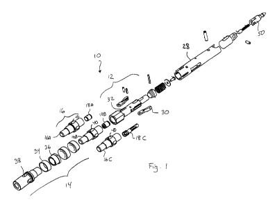
Figure 1 is an exploded view of a head assembly according to a preferred
embodiment of the present invention, with interchangeable mid latch bodies.
Figures 2A to 20 are cross-sectional side views of a head assembly according
to
another preferred embodiment of the present invention.
CA 02859831 2014-06-19
WO 2013/110159
PCT/CA2012/050045
8
Figures 3A to 30 are detailed cross-sectional side views of the head assembly
corresponding to the views shown in Figures 2A to 20, illustrating flow
streamlines
through the valve assembly.
Figure 4 is a detailed cross-sectional side view of an inner tube member of
another
preferred embodiment of the present invention.
PREFERRED EMBODIMENTS OF THE PRESENT INVENTION
Before any embodiments of the invention are explained in detail, it is to be
understood that the invention is not limited in its application to the details
of
construction and the arrangement of components set forth in the following
description or illustrated in the following drawings. The invention is capable
of other
embodiments and of being practiced or of being carried out in various ways.
Also, it
is to be understood that the phraseology and terminology used herein is for
the
purpose of description and should not be regarded as limiting. The use of
"including," "comprising," or "having" and variations thereof herein is meant
to
encompass the items listed thereafter and equivalents thereof as well as
additional
items. Unless specified or limited otherwise, the terms "mounted,"
"connected,"
"supported," and "coupled" and variations thereof are used broadly and
encompass
both direct and indirect mountings, connections, supports, and couplings and
are
thus intended to include direct connections between two members without any
other
members interposed therebetween and indirect connections between members in
which one or more other members are interposed therebetween. Further,
"connected" and "coupled" are not restricted to physical or mechanical
connections
or couplings. Additionally, the words "lower", "upper", "upward", "down" and
"downward" designate directions in the drawings to which reference is made.
The
terminology includes the words specifically mentioned above, derivatives
thereof,
and words or similar import.
CA 02859831 2014-06-19
WO 2013/110159
PCT/CA2012/050045
9
Referring now to the drawings in detail, wherein like numbers are used to
indicate
like elements throughout, there is shown in FIG. 1 an exploded view of a
presently
preferred embodiment of an core barrel head assembly 10 for a drilling
apparatus.
The core barrel head assembly 10 is positionable within a drill string of a
drilling
apparatus. The core barrel head assembly 10 comprises an upper latch body 12
and
a lower latch body 14. The head assembly 10 further comprises a mid latch body
16
separating the upper latch body 12 from the lower latch body 14 and removably
coupling the upper latch body 12 to the lower latch body 14. Figure 1 shows
three
different sample embodiments of the mid latch body 16A, 16B, 160 to illustrate
the
interchangeability of the mid latch body 16. In all cases, the mid latch body
16 is
removably coupled to the upper latch body 12 and the lower latch body 14. The
mid
latch body 16 houses a landing indicator device 18. A common central bore 20
is
formed by the upper latch body 12, the lower latch body 14 and the mid latch
body
16.
Preferably, as illustrated in Figure 1, the head assembly includes an upper
latch
body 12 with a latching assembly 30 and fluid pressure communication ports 32.
The
lower latch body 14 holds a landing shoulder 34 by a removable sleeve 36 and
includes fluid flow ports 38 downstream of the landing shoulder. The mid latch
body
component 16 also has fluid flow ports 40 upstream of the landing shoulder,
and
connects the upper and lower latch bodies, 12,14, with a central bore 20
connecting
the fluid flow ports 38,40. The mid latch body 16 contains a valving mechanism
42
which can provide a landing indication signal. The common central bore 20 is
present through all body components. The head assembly preferably includes of
two
sets of ports: the first set for fluid pressure communication with the
internal valving
mechanism 42, the second set for fluid flow required for drilling in which the
fluid flow
is blocked or opened by the internal valving mechanism 42. This fluid port
design
offers the advantages of increased fluid flow during drilling which means it
is less
CA 02859831 2014-06-19
WO 2013/110159
PCT/CA2012/050045
likely to collect debris and pack with mud and thus results also in a more
efficient
pumping system, compared to a head assembly where all the fluid circulates
through
a single port system upstream of the landing shoulder (thus more subject to
blockage) from the upper latch body to the lower latch body, with no bypass
port.
5 Given the reconfigurable nature of the head assembly, different valving
systems can
be used depending on drilling conditions and also can be easily upgraded when
a
newer type of valve is developed. Figure 1 illustrates an example of three
different
head assemblies in which the upper 12 and lower 14 latch bodies are similar
and
could be shared, but where a changeout of the mid latch body 16 allows the use
of
10 different valving mechanism designs that can be tailored to a specific
drilling
condition.
The following section illustrates an embodiment of a valving mechanism that
can be
changed out through replacement of the mid latch body 16 while also benefiting
from
the advantages of having the distinct fluid pressure communication ports 32
and fluid
flow ports 40 upstream of the landing shoulder.
Timed Signal Valve
Referring now to the drawings, there is shown in FIG. 2A to 30 a first
preferred
embodiment of a valve assembly 100 for use in an inner tube member 112 of a
core
barrel head assembly positionable within a drill string of a drilling
apparatus. The
valve assembly 100 comprises at least one pressure port 32 formed in a
sidewall of
the inner tube member 112. There is also at least one fluid flow port 40
formed in the
sidewall of the inner tube member 112.
Preferably, in a first descent configuration, a pressure piston member 118 is
positioned on top of an annular element, preferably a bushing 120, wherein the
piston member 118 and bushing 120 are in sealed engagement. The piston member
118 is preferably held in place by a compression spring 124 that is acting on
a latch
piston 126 that is connected to a retracting case 28 through a pin 127. The
retracting
CA 02859831 2014-06-19
WO 2013/110159
PCT/CA2012/050045
11
case 28 serves as a linkage element between the latch piston 126 and the
piston
member 118, as it is connected to the piston member through another pin 129
that
traverses the upper latch body 12 through a slot. A valve member 130 blocks
the
fluid flow ports 40 of the mid latch body 16. Preferably, seal members or 0-
rings 134
on the valve member 130 ensure proper sealing of the flow ports 40. The valve
member 130 is connected to the pressure piston member 118 by a connecting rod
136. The pressure piston member 118 is connected directly to the retracting
case 28
or has a limited movement connection with the retracting case 28, holding it
in a
middle, latch-retracted position, allowing the inner tube member 12 to travel
in the
drill string at an increased rate due to a reduction in the drag of the
latches on the
inside wall of the drill string, thus also reducing wear of the latches. As
described
above, the interaction between the pins 127,129 and the slots in the upper
latch
body 12 and slots in the retracting case 28 can help provide the limited
movement
connection of the piston member 118 with respect to any movement of the
retracting
case.
Preferably, as shown in FIG, 2A and 3A, when the inner tube member 112 reaches
the end of the drill string, a landing shoulder 34 will create a seal with the
landing
ring 35. This seal will build up the water pressure in the drill string. The
valve
member 130 blocks flow through the flow port 40 and the common bore 20 towards
the lower latch body 14. This built-up pressure is transferred to the pressure
piston
member 118 through the pressure communication port 32. At a predetermined
pressure, the force acting on the pressure piston member 118 will be great
enough
to push the piston member 118 through the bushing 120 and moving the head
assembly into its second, drilling position. The increased pressure acts as a
signal to
the driller that the assembly has reached the end of the drill string and the
latches
142 have extended to lock the head assembly into place. The interaction and
relative
displacement between the piston member 118 and the annular element or bushing
120 can help provide to the operator a pressure signal for a significant
length of time.
CA 02859831 2014-06-19
WO 2013/110159
PCT/CA2012/050045
12
As shown in FIG. 2B and 3B, when the piston member 118 has moved below and
further past the bushing 120, the valve member 130 is also moved down to open
the
fluid flow ports 40 for drilling. The retracting case 28 is also moved to a
lower,
latched-extended position. This position can only be achieved when the latches
142
are able to fully extend, in a latched configuration, as the latches will keep
the latch
piston 126 from moving to the proper locked position (through the interaction
between the pin 127 and the corresponding slot in the retracting case 28) if
the
landing position is incorrect.
Continuing the operation of the valve assembly, a retrieval device can be
preferably
latched onto a spearhead 50 when the inner tube member 112 is ready to be
brought back to the surface. The spearhead 50 is connected to the retracting
case
28. When pulled by the retrieval device, the spearhead 50 will unlock the
latches 142
and the assembly will be in a third, retrieval, position as shown in FIG. 2C
and 3C.
This movement of the retracting case 28 also moves the pressure piston member
118 back on top of the bushing 120 and moves the valve member 130 back, past
the
drilling fluid flow ports 40, leaving the flow ports 40 open slightly to allow
fluid flow
during retrieval. The pulling of the retrieval device moves the assembly from
the
second position to the third position.
When the retrieval device is removed from the spearhead 50, the compression
spring 124 will automatically reset the system and move the valve assembly
components to their first, descent position. Ports in the assembly although
shown as
being radial in the figures an also be axial in direction.
Alternatively, in another embodiment of the present invention, the valve
member 130
used to open and close the flow ports 40 may be part of the retracting case
28.
Another embodiment based on the valve assembly shown in Figures 2A to 3C, can
also be provided. As mentioned above, the valving assembly comprises a piston
member 118 mounted for axial movement within the mid latch body 16. A valve
CA 02859831 2014-06-19
WO 2013/110159
PCT/CA2012/050045
13
member 130 is mounted for axial movement within a central bore 20 of the mid
latch
body 16. First biasing means can be provided to urge the valve member 130
towards
a blocking position for blocking fluid flow between the fluid flow port 40 and
the
central bore 20. Second biasing means (not shown) urge the piston member 118
away from the flow port 40, the second biasing means having a biasing force
greater
than the first biasing means. Releasable locking means 125 are provided for
releasably locking the piston member 118 to the valve member 130 when the
piston
member 118 is in proximate engagement with the valve member 130.
Upon alignment of the at least one pressure communication port 32 with at
least one
aperture or port of an external port blocking structure, fluid pressure of a
predetermined value through the at least one pressure communication port 32
urges
the piston member 118 towards lockable engagement with the valve member 130.
Upon reduction of the fluid pressure below the predetermined value, the second
biasing means overcomes the first biasing means and urges the valve member 130
away from the blocking position and allows circulation of fluid flow between
the fluid
flow port 40 and the central bore 20.
The valving assembly illustrated in the preferred embodiment shown in Fig. 2A
to 30
consists of separate pressure communication ports 32 and fluid flow ports 40.
Such
a design eliminates fluid flow obstructions and limitations with using a
single set of
ports for both fluid pressure signals and fluid flow upstream of the landing
shoulder,
as is the case in current and past designs known in the art. Preferably, the
fluid flow
ports 40 are downstream from the pressure communication ports 32. The fluid
flow
ports 40, are blocked by the valve member 130, preferably a valve spool or
similar
valve element, in the initial first blocking position. The valve spool 130 is
releasably
connectable to the piston member 118, with the ability to lock to the piston
member
118 at a predetermined position. Relative motion between the valve spool 130
and
piston member 118 is biased to the closed position by the first and second
biasing
means, a weak spring and a strong spring respectively. This slideable
connection is
CA 02859831 2014-06-19
WO 2013/110159
PCT/CA2012/050045
14
lockable at a certain position and is manually or automatically unlockable.
Increased
fluid pressure is communicated via the pressure communication ports 32 to the
piston member 118 and acts to compress the strong spring. As pressure
increases,
the force on the piston member 118 increases, compressing the strong spring.
At a
predetermined pressure, the piston member 118 will have moved a predetermined
distance depending on the spring force. At this distance, the piston member
118 will
lock onto the valve spool 130. This can be achieved in any way, including a
ball lock,
lock finger, cam and pin, profiled slot and pin, the preferred method being a
ball lock
to lock pin. At this point, the driller or the computerized drill will notice
the increased
fluid pressure and will release the pumping pressure. When this is done, the
strong
spring will overcome the remaining hydrostatic pressure and move the piston
member 118 to its original position. The valve spool 130 which is now locked
onto
the piston member 118 is also moved with the piston member 118, opening the
fluid
flow port 40, allowing drilling fluid, such as water, to flow for drilling.
When the head assembly 10 is brought back to the surface, the valve spool 130
may
be automatically or manually unlocked from the piston member 118, closing the
port
40 and ready to be dropped back down the hole. Resetting of the valve may
occur
during ascent and retrieval, at the surface, or during unlatching and landing.
A
separate port or the same port may be opened to allow fluid flow during
retrieval to
avoid lifting the water column.
Preferably, the valve spool 130 may also be unlocked manually using a button,
a
twist lock, a pin or any other device or mechanism to unlock the spool from
the
piston. The weak spring will move the valve spool 130 to the blocked position
when
the valving mechanism is reset.
Preferably, to provide a substantial seal and to block fluid flow when
desired, the
valve spool 130 may contain some sort of sealing member or device such as an o-
ring or gasket 134.
CA 02859831 2014-06-19
WO 2013/110159
PCT/CA2012/050045
Preferably, to make the system operational at different depths and water
pressures,
the springs may be changed with different spring rates (or adjusted through
adjustment mechanisms to match the drilling condition.) The piston diameter
and/ or
5 surfaces areas may also be changed to the same effect.
Preferably, the valving assembly 100 may be an integral part of the mid latch
body or
constructed as a separate removable and/or replaceable assembly.
Alternatively, the
valve can block or open, to allow fluid flow, any of the following locations:
below the
10 fluid flow ports, at the central bore and above the fluid flow ports.
Another aspect of the present invention is to provide a mechanism that can
help
absorb momentum of the head assembly upon landing thereof. Such a mechanism
is illustrated in Figure 4. In this embodiment of the present invention, the
piston
15 member 118 comprises a slotted aperture 300, and a linking member, such
as a pin
129, slideable within the slotted aperture 300 and connected to the retracting
case
28. A biasing element 302, such as a spring or any other mechanical
equivalent,
urges the linking member 129 towards abutted engagement with an extremity of
the
slotted aperture 300 within the piston member 119 and for absorbing momentum
of
the core barrel head assembly upon landing of the landing shoulder with a
corresponding structure of the inner tube assembly. As it can be seen from the
figure, the biasing element 302 will more specifically absorb the momentum of
the
linking member or pin 129 that is linked to the retracting case 28, as the pin
attempts
to slide within the slotted aperture 300 upon landing, but is restrained by
the biasing
element.
Although preferred embodiments of the present invention have been described in
detail herein and illustrated in the accompanying drawing, it is to be
understood that
the invention is not limited to these precise embodiments and that various
changes
CA 02859831 2014-06-19
WO 2013/110159 PCT/CA2012/050045
16
and modifications may be effected therein without departing from the scope of
the
present invention.