Note: Descriptions are shown in the official language in which they were submitted.
CA 02860003 2014-06-19
WO 2013/096850
PCT/US2012/071397
APPARATUS AND METHOD FOR IMAGING VASCULATURE AND SUB-DERMAL
STRUCTURES BY TRANS-ILLUMINATING NIR LIGHT
BACKGROUND OF THE INVENTION
[0001] Medical diagnosis, treatment and therapy methods and systems can employ
the
transmission and imaging of near-infrared light into and through the human
body for viewing
blood vessels and other sub-dermal structures in the body. The administration
of medical care
to a patient often requires vascular access. Expeditious administration of
medical care to the
victim or patient improves the prospects of recovery for the victim or
patient. Patients may
have veins that are partially collapsed, or veins that are difficult to find
or difficult to access
(such as in the treatment of infants or geriatric persons), which further
complicates procedures
for gaining access to the veins. The treatment of patients requiring vascular
access may also be
complicated by patient size (a neonate), obesity, skin pigmentation or other
physical
characteristic that can reduce peripheral circulation.
[0002] In the practice of the procedures for visualization of subcutaneous
structures by
trans-illumination using infrared or near-infrared light, proper support of
the light source in order
to effectively direct the light onto a body portion of interest may be an
awkward procedure for
the health care provider in treating a patient. US Patent 7,925,332, issued to
Crane et al on
April 12, 2011 (the disclosure of which is incorporated herein by reference)
discloses a
multi-layered structure in the form of a disposable patch useful in
conjunction with procedures
for the non-invasive visualization of veins, arteries or other subcutaneous
structures of the body
or for facilitating vascular insertion of needles or catheters for
administration of fluids and
medication, measurement of physiological parameters, extraction of venous or
arterial blood, or
the like. The patch is particularly useful in conjunction with systems and
methods for the
detection and display of subcutaneous structures such as described in U.S.
Patent 6,230,046 to
Crane et al (the disclosure of which is incorporated herein by reference),
which describes
systems and methods for enhancing the visualization of veins, arteries or
other subcutaneous
natural or foreign structures in the body and for facilitating vascular (both
venous and arterial)
insertion or extraction of fluids, medications or the like in the
administration of medical
treatment to a patient, including a light source of selected wavelength(s) for
illuminating or
trans-illuminating a selected portion of the body and a low-level light
detector and suitable filters
for generating an image of the illuminated body portion.
CA 02860003 2014-06-19
WO 2013/096850
PCT/US2012/071397
[0003] US Patent Publication US 2004-0215081 (the disclosure of which is
incorporated
herein by reference) discloses a real-time visualization and detection of an
extravasated or
infiltrated fluid in subdermal or intradermal tissues at a site of an
intravascular injection by
illuminating an intended site of an intravascular injection with infrared
light from a light
source and generating real-time images of the body and the injected fluid to
determine
differences in contrast evidencing extravasation or infiltration of said fluid
near the vasculature
within the body.
[0004] Medical technicians and professionals work under a variety of lighting
conditions,
including surgical operating rooms, clinics, and doctor's offices that employ
high intensity
lighting, fluorescent lighting, incandescent lighting, and visible LED
lighting. Medical
personnel can use different modes of visualizing the trans-illuminated IR
light. In one type of
procedure, the medical personnel can view the trans-illuminated infrared light
employing an
intensifier tube or similar display device similar to night vision goggles, as
described in Crane et
al, supra. In another procedure, an image of the trans-illuminated IR light is
displayed on a
display device or monitor that the medical personnel view with the unaided
eyes. Such display
device or monitor can be a liquid crystal display (LCD), LED display, gas
plasma, cathode ray tube
or other display that receives an image of the infrared light captured by a
camera or imaging
device. The display device can be within reach of the medical personnel as
shown in PCT Patent
Publication WO 2010/059045 (the disclosure of which is incorporated by
reference in its entirety),
or on a computer screen or display remote from the patient.
[0005] In ambient lighting that has an output having a cycled maxima and
minima, such as
fluorescent lights, the pulsing of the IR light source can be synchronized
with the minima of the
output from the ambient room, and gated with the light detector (camera), as
described in US
Patent Publication 2004-0215081, the disclosure of which is incorporated by
reference in its
entirety.
[0006] The work of medical personal is highly skilled and requires focus and
attention to
perform procedures and diagnose medical conditions with a minimum of
distraction and
complexity. Despite numerous advances in the illumination and trans-
illumination of the
human body with infrared light, in the detection of trans-illuminated infrared
light from the
illuminated body, and in the imaging and viewing of the detected light
signals, there remains a
need for improved methods and systems for use by medical personnel to provide
high quality
images of the sub-dermal structures that is convenient, rapidly deployable,
and easy to use and
2
CA 02860003 2014-06-19
WO 2013/096850
PCT/US2012/071397
avoids confusion and complexity.
SUMMARY OF THE INVENTION
[0007] The present invention provides an imaging system for visualizing,
including
real-time visualization of, sub-surface structures, including sub-dermal
structures, in a body part,
including an extremity, of an animal, typically a mammal. The system includes
a near-infrared
(nIR) illumination source that emits nIR light that trans-illuminates the body
part of the animal.
The imaging system also includes a camera that captures the trans-illuminating
nIR light. The
camera typically includes a zoom lens to provide a detection field of view at
a long working
distance for the camera from the animal body part, the long working distance
being sufficient to
avoid the camera obstructing a visual field of view of a user, typically a
medical personnel, when
performing a procedure such as a medical or examination procedure on the body
part. The
camera can be attached to the distal end of the upper arm.
[0008] An imaging system can also include a targeting system for indicating a
center of
detection field of view, and optionally a focus distance of the zoom lens. The
imaging system
can also include an image processor for converting the captured trans-
illuminating nIR light to an
image signal. The imaging system also includes a visual display device, which
can be attached
to a distal end of the lower articulating arm. The visual display device can
include a visual
display screen, at least one controller for sending a control signal to the
camera, for sending
power and control signals to the nIR illumination source, and for transmitting
the processed
image signal to the visual display screen.
[0009] The invention also can provide an imaging system for visualization,
typically in
real time, of surface and sub-surface structures in a body part or an
extremity of an animal, the
system including: a near-infrared (nIR) illumination source that emits nIR
light that
trans-illuminates an animal body part; a camera including a zoom lens; a
targeting system for
indicating a focus location and a center of detection field of view of the
zoom lens; an image
processor for converting the captured trans-illuminating nIR light to an image
signal; and a
visual display device including a controller for sending a control signal to
the camera, and for
sending power and control signals to the nIR illumination source, and a
display screen that
receives and displays the processed image signal.
[0010] The present invention can provide an imaging system for real-time
visualization
of sub-surface structures in a body part of a mammal, the system including: a
near-infrared (nIR)
3
CA 02860003 2014-06-19
WO 2013/096850
PCT/US2012/071397
illumination source that emits nIR light that trans-illuminates the body part;
a support structure
that includes an upright post, a lower arm extending from the upright post,
and an upper arm
extending from an upper portion of the upright post and including a distal
end, wherein the upper
arm and the lower arm articulate independently; a camera attached to the
distal end of the upper
arm that captures the trans-illuminating nIR light, the camera including a
zoom lens to provide a
detection field of view at a long working distance for the camera from the
body part, the long
working distance being sufficient to avoid the camera obstructing a visual
field of view of the
medical personnel when performing a medical procedure on the body part; a
targeting system
associated with the camera for indicating a focus location of the zoom lens
and a center of
detection field of view; an image processor for converting the captured trans-
illuminating nIR
light to an image signal; a visual display device attached to a distal end of
the lower articulating
arm and including a visual display screen; and at least one controller for
sending a control signal
to the camera, for sending power and control signals to the nIR illumination
source, and for
transmitting the processed image signal to the visual display screen.
[0011] The system can also include a support structure for one or more
components of
the imaging system. The support structure can include an upright post, and an
upper arm which
can extend from an upper portion of the upright post, and optionally a lower
arm extending from
the upright post. The upper arm and any lower arm articulate independently.
The support
structure can be a fixed support, including a wall or other building or
vehicle structural element.
The support structure can also be a mobile support.
[0012] The present invention also provides an imaging system for real-time
visualization
of sub-surface structures in a body part of a mammal, the system including: a
near-infrared (nIR)
illumination source that emits nIR light that trans-illuminates the body part;
a camera that
captures the trans-illuminating nIR light, the camera optionally including a
zoom lens to provide
a detection field of view at a long working distance for the camera from the
body part, the long
working distance being sufficient to avoid the camera obstructing a visual
field of view of the
medical personnel when performing a medical procedure on the body part; a
targeting system
associated with the camera for indicating a focus location of the zoom lens
and a center of
detection field of view; an image processor for converting the captured trans-
illuminating nIR
light to an image signal; a visual display device attached to a distal end of
the lower articulating
arm and including a visual display screen; and at least one controller for
sending a control signal
to the camera, for sending power and control signals to the nIR illumination
source, and for
4
CA 02860003 2014-06-19
WO 2013/096850
PCT/US2012/071397
transmitting the processed image signal to the visual display screen.
[0013] In another aspect of the invention, the nIR illumination source is a
disposable nIR
light source device comprising a nIR-emitting light emitting diode (nIR-LED).
[0014] An imaging system of the invention can also include a filter for
passing nIR light
within a passband between 700 nm and 1000 nm.
[0015] In another aspect of the invention, the camera further includes an
imaging
processor that provides a logarithmic response to the intensity of nIR light
detected, and a 16-bit
gray scale resolution. In a further aspect, the controller can include a
computer, wherein the
image processor is integral with the camera or the computer, and wherein the
image processor
provides a logarithmic response to the intensity of nIR light detected, and a
16-bit gray scale
resolution.
[0016] In another aspect of the imaging system of the invention, the first arm
and the
second arm are independently swivelable on the upright post.
[0017] In another aspect of the imaging system of the invention, the visual
display device
is a touch-screen, display-integrated computer.
[0018] In another aspect of the imaging system of the invention, the
controller pulses
and/or adjusts the intensity of the illumination output of the nIR
illumination source, and controls
a gate opening in the camera for capturing temporal image signals in
synchronization with the
pulsed maxima of the nIR illumination source output.
[0019] The present invention also provides an imaging system for real-time
visualization
of sub-surface structures in a body part of a mammal, the system including: a
near-infrared (nIR)
illumination source that emits nIR light that trans-illuminates a mammalian
body part; a camera
including a zoom lens to provide a detection field of view at a long working
distance for the
camera from the body part, the long working distance being sufficient to avoid
the camera
obstructing a visual field of view of a medical personnel when performing a
procedure on the
body part; a targeting system for indicating a focus location of the zoom lens
and a center of
detection field of view; an image processor for converting the captured trans-
illuminating nIR
light to an image signal; and a visual display device including at least one
controller for sending
a control signal to the camera, and for sending power and control signals to
the nIR illumination
source, and a display screen that receives and displays the processed image
signal.
[0020] Another aspect of the present invention is a method for visualizing of
sub-surface,
including sub-dermal, structures in a body part or extremity of an animal,
including of a
CA 02860003 2014-06-19
WO 2013/096850
PCT/US2012/071397
mammal, comprising the steps of: positioning a camera disposed to capture
images of a
procedure on the body part; manipulating the camera to a field of view
detecting position by
aiming a targeting system at the body part to establish a center of detection
field of view, and
adjusting the focus location of the zoom lens; attaching a nIR illumination
source for fixed
positioning to an under-surface of the body part, and powering the nIR
illumination source to
trans-illuminate the body part; manipulating a viewing screen to a viewing
position in the visual
field of view of the user when performing the procedure; detecting the real-
time
trans-illuminating nIR light into a real-time trans-illuminated image; and
viewing the real-time
trans-illuminated image of the body part on the viewing screen while
performing the procedure
on the body part.
[0021] In another aspect of the invention, a further step includes
manipulating the
controller to change the detection field of view of the animal extremity by
adjusting the zoom of
the camera. The zoom feature can also increase the image size of the view
field, enabling
close-up or magnified views of the procedure field.
[0022] Another aspect of the present invention is a method for real-time
visualization of
sub-dermal body structures in a body part of a mammal, comprising the steps
of: providing an
imaging system according to the invention; positioning the camera can be above
the eye-line
(level of the eyes) of a medical personnel when positioned to perform a
medical procedure on an
extremity of a mammal, to avoid obstructing a visual field of view of the
medical personnel;
manipulating the camera attached to the distal end of the upper arm to a field
of view detecting
position by aiming a targeting system at the body part to establish a center
of detection field of
view, and adjusting the focus location of the zoom lens; attaching the nIR
illumination source for
fixed positioning to an under-surface of the body part, and powering the nIR
illumination source
to trans-illuminate the body part; manipulating the viewing screen attached to
the distal end of
the lower arm to a viewing position in the visual field of view of a personnel
when performing
the procedure, typically a medical procedure; detecting the real-time trans-
illuminating nIR light
into a real-time trans-illuminated image; and viewing the real-time trans-
illuminated image of the
body part on the viewing screen while performing the medical procedure on the
body part.
[0023] Another aspect of the invention is a multi-functional control feature
in a nIR
trans-illumination and imaging system that includes a nIR light emitting
source, a camera for
capturing trans-illuminating nIR light through a body portion of a patient, a
visual display device
for displaying a trans-illuminated image of the body portion, and a computer
for controlling the
6
CA 02860003 2014-06-19
WO 2013/096850
PCT/US2012/071397
nIR light emitting source, the camera, and the visual display device, and for
optionally further
processing of the captured image and displaying the processed image on the
visual display
device. The computer can include a single-action, multi-functional control
feature, or a
multi-action, multi-functional control feature. The multiple functions of the
control feature
include the emission intensity of the light source, and at least one of the
following image
processing features: camera gain, sharpness, and camera spatial resolution.
[0024] The multi-functional control feature can be positioned between a first
position
associated with a first imaging condition that employs low light emission from
the nIR light
source, and at least one of low camera gain, and high camera spatial
resolution, and high image
sharpness, and a second position associated with a second imaging condition
that employs high
light emission from the nIR light source, and at least one of high camera
gain, low camera spatial
resolution, and low image sharpness.
[0025] A multi-action, multi-functional control feature provides at least two
control
features that operate between a first position and a second position. The pair
of control features
can be operated, or can operate, independently, or optionally they
interactively can be selectively
locked or linked together to operate together. One of the controller provides
control of the nIR
light source intensity while the other controls nIR sensitivity and image
resolution. The nIR
Sensitivity and the nIR illumination intensity are selected and optimized to
obtain optimal visual
images.
[0026] A single-action, multi-functional control feature operates between a
first position
and a second position. The first position is associated with a first imaging
condition that
employs low light emission from the nIR light source, low camera gain, and
high camera spatial
resolution, and high image sharpness, and is typified by the imaging of
neonate patients. The
second position is associated with a second imaging condition that employs
high light emission
from the nIR light source, high camera gain, low camera spatial resolution,
and low image
sharpness, and is typified by the imaging of adult patients with large
muscular body parts.
Operating the control feature at and between the first and second positions
provides simultaneous
and interconnected control of both the nIR light transmission and camera and
processor setting
between the two extremes.
[0027] Another aspect of the invention is a method for real-time visualization
of
sub-dermal body structures in a body part of an animal, comprising the steps
of: a. providing a
system including a nIR light emitting source, a camera for capturing trans-
illuminating nIR light
7
CA 02860003 2014-06-19
WO 2013/096850
PCT/US2012/071397
through a body portion of a patient, a display device for displaying a trans-
illuminated image of a
body portion of the patient, and a computer for controlling the nIR light
emitting source, the
camera, and the display device, and for processing of the captured image and
displaying the
processed image on the display device; providing a multi-functional control
feature that operates
the intensity of the light source and at least one of camera gain, camera
spatial resolution, and
image sharpness, the multi-functional control feature positionable between a
first position
associated with a first imaging condition that employs low light emission from
the nIR light
source, and at least one of low camera gain, and high camera spatial
resolution, and high image
sharpness, and a second position associated with a second imaging condition
that employs high
light emission from the nIR light source, and at least one of high camera
gain, low camera spatial
resolution, and low image sharpness; initiating an imaging procedure of the
body portion of an
animal patient; and selecting the position of the multi-functional control
feature in accordance
with the nIR transmission requirements of the body portion, to provide
control, typically
simultaneous and interconnected control, of the light emission from the nIR
light source and the
at least one of camera gain, camera spatial resolution, and image sharpness.
[0028] The devices, systems and methods are described for imaging the
extremities and
body parts of animals. The invention is particularly useful for imaging of
mammals including
humans, and also other genus and species of living creatures, including birds,
fishes, amphibians,
and reptiles, other vertebrates, and invertebrates, for various medical and
biological applications,
including by example, drugs testing.
BRIEF DESCRIPTION OF THE FIGURES
[0029] Figure 1 shows an illustration of an apparatus for imaging of nIR light
trans-illuminating a patient's body part.
[0030] Figure 2 shows an apparatus for imaging of nIR light trans-illuminating
a
patient's body part.
[0031] Figure 3 shows a schematic diagram of the nIR light illumination and
trans-illumination through the patient's extremity, and the power and control
connections for the
light source, camera, and visual display device.
[0032] Figure 4 illustrates a visual display device showing a patient's hand
and a touch
screen interface with a single, multi-function slide mechanism for controlling
the camera, the
light source, and the image processing.
8
CA 02860003 2014-06-19
WO 2013/096850
PCT/US2012/071397
[0033] Figure 5 illustrates another embodiment of a visual display device
showing the
patient's hand and a touch screen interface with a dual slide mechanism for
controlling the
camera, the light source, and the image processing.
DETAILED DESCRIPTION OF THE INVENTION
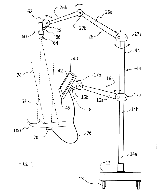
[0034] Figure 1 shows an imaging system 1 for use by medical personnel for
real-time
visualization of sub-dermal body structures of an animal patient. A support
structure is
illustrated as a mobile stand 10 that provides a support structure for a
camera 60 and a visual
display device 40. The mobile stand 10 includes a base 12, an upright post 14
attached to the
base 12 at a lower portion 14a. The post 14 includes an intermediate portion
14b, and can
include an upper portion 14c. The base 12 extends laterally to provide
adequate stable support
for the upright post and its parts and accessories to prevent tipping. The
base 12 is typically a
weighted circular or rectangular platform of heavy material or having added
weight for stability
(as illustrated in Figure 1), and may include a plurality of radially
extending legs (as illustrated in
Figure 2) that ensure stability of the mobile stand and the entire system.
Wheels 13 can be used
on the base 12 for rolling the mobile stand 10 into position for the
procedure, which can
optionally be blocked or locked. The mobile stand is light weight and stable,
with the post 14
and extending arms positioned at a height sufficient so as not to interfere
with hospital beds and
bed rails.
[0035] A lower arm 16 extends from the intermediate portion 14b of the upright
post 14
and can be articulated into a position for optimal viewing of the visual
display 42 of the display
device 40 by the medical technician. A first lower arm segment 16a extends
from a hinged
connector 17a along the intermediate portion 14b. The hinged connector 17a can
be fixed to
the upright post 14. The hinged connector 17a may optionally include an
adjustment
mechanism so that the whole lower arm 16 assembly can be selectively moved
upwardly and
downwardly to a stationary position vertically along post 14. The first lower
arm segment 16a
can be configured to pivot selectively at the hinged connector 17a in a
vertical plane (for
example, out to 80 up or down from horizontal) or to swivel selectively in a
horizontal plane
(for example, out to 180 left or right) around the axis of the post, using
well known joint means.
A second lower arm segment 16b can be attached at a manipulable connector 17b
to the distal
end of the first lower arm segment 16a, for similar movement in the vertical
and horizontal
planes.
9
CA 02860003 2014-06-19
WO 2013/096850
PCT/US2012/071397
[0036] The display device 40 is attached to the distal end of the second lower
arm
segment 16b at a manipulable connector 18. The connectors 17a, 17b, and 18 can
be
configured for pivoting, swiveling or rotating along the axis by well-known
means, for infinite
positioning of the display device. The combination of connectors at 17a, 17b
and 18 enables
location of the display device according to the medical technician's personal
preference to
visualize the vascular image on the visual display for its use by the
technician in performing a
vascular access procedure while at the same time not obstructing the view of
the patient,
particularly the patient's face, as a means for the technician to continually
assess the patient's
condition and response to the procedure. Because of the ease of moving the
visual display
provided by connectors 17a, 17b and 18 and locking of the wheels 13 of the
base 12, positioning
of the visual display can be performed without disturbing the location of the
mobile stand 10 or
position of camera 60.
[0037] An upper arm 26 extends from the upper portion 14c of the upright post
14, above
the lower arm 16, and can be articulated into a position for optimal capturing
of the
trans-illuminating nIR light 74 from the light source 70 by the camera 60. A
first upper arm
segment 26a extends from a hinged connector 27a at the distal end of or along
the upper portion
14c. The hinged connector 27a can be fixed to the upright post 14. The hinged
connector 27a
may optionally include an adjustment mechanism so that the whole upper arm 26
assembly can
be selectively moved upwardly and downwardly to a stationary position
vertically along post 14.
The upper arm 26 can be configured to pivot selectively at the hinged
connector 27a in a vertical
plane or to swivel selectively in a horizontal plane around an axis of the
post, using well known
joint means. A second upper arm segment 26b can be attached at a manipulable
connector 27b
to the distal end of the first upper arm segment 26a. The camera 60 is
attached to the distal end
of the second upper arm segment 26b at a manipulable connector 28. The
connectors 27a, 27b
and 28 can be configured for pivoting, swiveling or rotating along the axis by
well known means,
for infinite positioning of the camera.
[0038] The upper arm 26 extends from the upright post 14, and the upper arm
members
26a and 26b have sufficient length that the camera can be positioned across a
hospital bed, table
or gurney above a patient body part and at a sufficient height over the body
part to provide the
typical camera working distance of 12 to 36 inches, to enable positioning the
camera 60 near or
above the level of the eyes of the medical practitioner who is positioned to
perform the medical
procedure. This positioning of the camera further prevents its obstructing the
medical
CA 02860003 2014-06-19
WO 2013/096850
PCT/US2012/071397
personnel's visual field of view of the image area of the procedure when
performing the medical
procedure on the body portion. The length of the upper arm members 26a and 26b
also permit
positioning of the camera into and over a variety of medical-related equipment
and facilities,
including over a neonatal infant incubator at the typical working distance so
that a procedure can
be performed on the infant without removing the infant from the incubator, in
critical care
facilities, and over an operating room table.
[0039] The lower arm 16 and the upper arm 26 are constructed of aluminum,
steel, or
high strength plastic tubular members for strength, light weight, and passage
of electrical and
control wiring between the electronic components of the system. The joints and
connections
between sections of the arms and between the arms and the devices can include,
for example and
without limitation, springs, friction-based adjustments, tensioning joints,
weight balancing
means, and quick-release fasteners to provide adjustable and stationary
positioning for
independent pivoting or swiveling of the arm members and the devices.
[0040] Alternatively, a support structure from which at least one of the upper
and lower
arms can depend can be a fixture. Non-limiting examples of fixtures to which
the support
structure can be fixed include a table, or bed, and a wall, and the fixture
can be a portion or
element of a building, field hospital, water vessel, or air-based emergency
vehicles such as
ambulances and helicopters. BTW, these do not vary too much from the figures
that you show
except for the mobile stand. such as
[0041] The base 62 of the camera 60 is attached to the distal end of the upper
arm 26 at
the manipulable connector 28 by well known means. The camera 60 can be
articulated into
position for optimal viewing of the nIR light reflecting or trans-illuminating
the body portion
during the procedure.
[0042] To obtain a detailed image and a full field of view of the body
portion, with the
camera positioned up and away from the work area of the medical personnel
performing the
procedure, the camera 60 can employ a zoom imaging feature. The zoom feature
can include a
zoom lens 64, as illustrated in Figure 1, or digital zoom processing, alone or
in combination with
a zoom lens. The zoom lens 64 can be a fixed zoom lens selected to provide a
fixed field of
image at a selected, predetermined distance from the body portion, or can have
a variable zoom
feature that is either manually adjustable or remotely adjustable
electronically from a controller.
The zoom lens system may include a field of view capability with a broad range
ratio of object
size to image size. The range ratio can include 1:2 to 5:1, or more, including
a 1:1 "life size"
11
CA 02860003 2014-06-19
WO 2013/096850
PCT/US2012/071397
ratio. A smaller field of view provides a magnified image that facilitates
close-ups and an
increased size of view for neonate and pediatric patients. At the same time,
the lens system may
be configured so that the object lens distance remains the same and remains in
focus. An
autofocusing capability may be included in the camera 60 selected for use in
system 1. The
long working distance of the camera provided by the zoom lens is sufficient to
avoid the camera
obstructing a visual field of view of the medical personnel when performing a
medical procedure
on the patient. The typical working distance from the lens of the camera to
the object (the body
portion of the patient) is 4 ¨ 36 inches, with examples of a more typical
working distance being
about 4 - 26 inches, 12 - 36 inches, and 22 - 24 inches.
[0043] The
camera 60 is typically a solid-state, digital nIR-sensitive camera. A
non-limiting example of a solid-state, digital nIR-sensitive camera is a Sony
ICX618AQA,
having an interline CCD solid-state image sensor 69 with a square pixel array
which supports
VGA format. The Sony ICX618AQA includes progressive scan that enables all
pixel signals to
be output separately within approximately 1/60 second, and employs the EXview
HAD CCDTM
that includes near-infrared light region typically in the range of from about
700 nm to about 1000
nm, as a basic structure of HAD (Hole-Accumulation Diode) sensor.
[0044] A
narrow bandpass filter 68 can be used to pass near-infrared light of a
selected range, typically between 840 nm and 875 nm, and more typically about
850 nm + 20
nm. An electronic interface on the camera sends an image signal and other data
concerning
camera operation to a controller, and sends power and control signaling from
the electronic
interface to the camera. Other systems accomplishing the intended purpose may
be selected by
one with skill in the art within the intended scope of the teachings herein
and of the appended
claims.
[0045] The system provides independent positioning of the camera and the
display
device, such that moving the viewing screen out of the way temporarily or
adjustment of the
viewing screen during use does not require re-manipulating and positioning of
the camera. This
saves substantial time for the medical personnel and reduces the risks of
making an error in, or
overlooking some aspect of, the medical procedure.
[0046] Figure 2 shows another imaging system 101 for real-time visualization
of
sub-dermal body structures of a patient, including a mobile stand 10 that
provides a support
structure for a camera 60 suspended from an upper arm 26 and a visual display
device 40
suspended from a lower arm 16, with a base 12 having five radially extending
legs with casters
12
CA 02860003 2014-06-19
WO 2013/096850
PCT/US2012/071397
13 for stable mobility. The castors 13 can include a lock to limit rolling
movement of the stand
10. The camera 60 is mounted on a bracket 161 having a pair of extending
handles 163 to aid
positioning and aiming of the camera.
[0047] To aid in the determination of the camera focal distance and an optimal
image
focus, and for directing the field of view of the camera at the body portion
target, the imaging
system can employ a targeting system. A targeting system can comprise a
convergent laser
spotting device can include intersecting light (e.g., using laser diode lights
or incoherent LED
light sources) to generate two points of light that converge at a point of
convergence at a focal
range or distance from the camera lens. In one embodiment, the point of
convergence of the
targeting system is a distance (the convergence point distance) within the
intended camera
operating zone of 12-36 inches; for example, 22 inches. The convergent laser
spotting device
or mechanism indicates a reference distance of the camera, projected toward
the body part, and a
center of detection field of view of the camera image. Typically the targeting
system works at
least within the camera operating zone of 12-36 inches. An example of a laser
focal distance
system is described in Laser Ranging: a critical review of usual techniques
for distance
measurement, Markus-Christian et al., Optical Engineering, Vol. 40, No. 1,
p.10-19, 2001, the
disclosure of which is incorporated herein by reference.
[0048] Figure 2 shows the location of a pair of laser pointers 165 on the
underside of the
bracket 161 of the camera unit. The laser pointers orient the camera with
respect to the area of
the body part to be imaged. The two laser pointers emit beams of light
(typically red light beams)
along a beam path 167 to intersect at a fixed-distance, single intersection
point 169. The two
laser pointers 165 can be powered 'on' by a dedicated power switch, or by the
computer that
controls the power and control to the camera. If the surface of the body part
(for example, the
skin of the forearm of a patient) is positioned at the point of convergence of
the targeting system,
then a single visible point of light appears on the surface. If the body part
is positioned closer
to the lens, or farther from the lens, than the convergence point distance,
then two points of light
will appear a converging distance apart on the surface, proportional to the
distance of the surface
from the convergence point distance. Typically within the intended camera
operating zone of
12-36 inches, either or both points of light appear on the surface. The
location of the beam
paths 167, and their intersection point 169, can be observed as visible points
of light on the
surface of the patient's body, and on the visual image presented on the visual
display screen, as
illustrated in Figure 5
13
CA 02860003 2014-06-19
WO 2013/096850
PCT/US2012/071397
[0049] A lever 164 on the bracket 161 can be manipulated within a slot that is
labeled
with a scale of magnification factors from about 1X to about 2.25X. The lens
can be a macro
zoom lens that allows image zoom without object distance adjustment, which
means that once
the image through the lens is in focus, the image remains in focus through the
zoom range. In
this way the 22 inch distance and center of the field of view indicated by the
convergent laser
beams is consistently true even as the lever 164 is adjusted to zoom in on
pediatric subjects for a
magnified view. As shown in Figure 3, emitting nIR light 73 is provided by a
nIR light source 70
that is attached in photo-communication with the body portion (extremity) 100
of the patient.
[0050] The nIR light source is preferably small, disposable light source that
is attachable
to the skin surface of the patient so that the nIR light passes directly into
and through the body
portion, and is securable to the body portion to avoid movement or jostling of
the light source
during use. Examples of lights sources for emitting nIR light for imaging
include coherent laser
diodes and non-coherent light emitting diodes (LEDs). The LED typically emits
nIR light in the
range of 700 nm to 1000 nm. Preferred is an LED with an emission 73 within the
range of 810
nm to 880 nm. The disposable light source (hereinafter, DLS) can have a
plastic release liner
on the light-emitting surface that allows the medical personnel to survey the
body portion for
veins and arteries, for example, for the best place to perform the vascular
access procedure
without exposing and disrupting an adhesive hydrogel. Once the desired
position has been
determined, the release liner can be removed (peeled off) from the hydrogel
adhesive base
material that provides both gentle adhesion to the skin (i.e., for neonates,
pediatrics, and
geriatrics) and optical coupling of the nIR illuminator (typically a nIR-LED)
and the skin of the
patient. The DLS provides for hands-free use during the procedure, while its
single use nature
serves as a barrier to spread of disease. The DLS can include one, two, three,
four or more light
emitters, depending upon the portion of the body to be imaged and the
requirements of the
medical procedure being viewed. The DLS can also have a proximity sensor that
controls current
to the nIR emitting diode, allowing the light source to turn on only when the
DLS is in proximate
contact with the patient's skin. An electronic interface is connected to the
nIR illumination
source for receiving power (in cases where the light source does not have on-
board battery
power) and for control signals. The electronic interface can be a wired
interface that connects
the light source to a remote controller, or can be a wireless interface,
including an optical or
radio frequency signal.
[0051] In an embodiment of the invention, the nIR illumination source is a
single use or
14
CA 02860003 2014-06-19
WO 2013/096850
PCT/US2012/071397
disposable light source (DLS) device that includes a light-directing and
transmitting structure
that can be applied to the skin surface of a portion of the body and a light
source supported by
the structure, including, but not necessarily limited to, a near-infrared
light source. The device
provides illumination of a body portion, and is useful in conjunction with
systems and methods
for real-time non-invasive visualization and identification of veins, arteries
and other
subcutaneous structures and objects in the body, in the administration of
medical treatment to a
patient, including facilitating intravenous insertion or extraction of fluids,
medication or the like,
and various surgical and diagnostic procedures affecting veins and arteries.
The illumination
can include trans-illumination, reflection, side illumination and
backscattering. In addition, this
light source permits the detection and identification of other natural
subcutaneous structures and
foreign objects such as metallic or plastic objects such as needles, stents,
catheters, or fiber optic
devices, or other non-natural items that could be present as a result of an
accident or placed in
situ for prosthetic purposes, or for the administration of medication or other
infused substances.
[0052] The DLS can also include a proximity sensor for detecting when the DLS
is
positioned in proximity to the surface of the body portion of the patient. The
proximity sensor
controls the flow of current to the light source, and turns 'on' (delivers
power to) the light source
only when the light-emission pathway of the DLS is in close proximity to or in
contact with the
body portion, and which turns off the flow of current of the light source when
the DLS is
removed from proximity to the body portion. The proximity sensor significantly
limits and
preferably prevents light, especially near-infrared light, of the DLS from
emitting generally in a
direction other than the body portion, to avoid inadvertent light emissions
that would become
noise in the detected image or could enter the eyes of the patient, medical
staff, or bystanders.
[0053] The DLS uses electrical power for the light source, and can include a
layer or film
of an electrically insulating material as a means for isolating electrically
the light source, and any
optional proximity sensor, from the body portion of the patient. The layer or
layers of
electrically insulating film or coating material prevents any electrical
current flowing from or to
the light source and associated electrical components of the DLS from flowing
through the
potentially electrically conductive conforming layer that is in direct contact
with the skin of the
body, thus avoiding and preventing electrical shocks or sensations or from
interfering with
additional medically placed instrumentation or sensors in the vicinity of the
light source. In
addition, the isolating layer also insulates the body surface from heat
generated by the
near-infrared light emitting diodes commonly used for illumination purposes
associated with
CA 02860003 2014-06-19
WO 2013/096850
PCT/US2012/071397
imaging the internal structures of the body.
[0054] The DLS can also include a light source wherein the source of
electrical power
and a controller for the light source are disposed remote from the DLS, to
minimize the
components, features, cost and complexity of the DLS. The simplicity of the
design and
components of the attachable and disposable light source can significantly
reduce the cost of
such device, allowing its use in a wider variety of medical procedures
involving vascular access
and subcutaneous imaging of the vasculature and the structures, or objects
(endogenous or
exogenous) with the body. The DLS can also include a disposable or replaceable
light source,
and a reusable structure that holds and electrically connects the light source
and proximity sensor
to a source of power and control. In addition, the DLS may be configured to be
battery-powered via an on-board battery, and may be directly wired for power
to an external
device, including the display device 40 or other source of power.
[0055] A description of a suitable nIR light source device and its means of
powering and
control are described in US Patent 7,925,332, issued to Crane, supra, in US
Provisional Patent
Application 61/513,689, filed August 1, 2011, entitled "Disposable Light
Source for Enhanced
Visualization of Subcutaneous Structures", and International Application
PCT/US2012/49231,
filed August 1, 2012, the disclosures of which are incorporated herein by
reference.
[0056] An important issue in the trans-illumination imaging of body portions
with nIR
light is the wide range of light intensities that need to be transmitted
through different human
body extremity types and conditions. For example, neonate's and children's
hands are
relatively thin, and will allow passage of a higher light transmission than,
for example, the
forearm of an adult male, which is much thicker. It is estimated that the
difference in
transmission between various body portion types is in some instances at least
four orders of
magnitude (10,000 x) or more. To provide effective imaging across such a wide
variation in
light intensity, the captured image processor can employ a logarithmic
response to light
irradiance and 16 bits of intensity resolution.
[0057] Image processing can be performed on a computing device 50 remote from
the
display device 40, or can be performed within or on the display device 40 with
an integrated
computer 50. The computer 50 can be interfaced wirelessly or with a wired
connection via
communication path 46 with the display device 40, and/or interfaced wirelessly
with a wired
connection via communication path 66 with the camera 60, and/or interfaced
wirelessly or with a
wired connection via communication path 76 with the light source 70. The
computer 50 and
16
CA 02860003 2014-06-19
WO 2013/096850
PCT/US2012/071397
the display device 40 can be fixed to the system 1, or either or both can be
portably carried by
the medical technician. The display device 40 can include a computer 45 with
an integrated
visual display screen 42 that allows the technician to control each of the nIR
light source
operation, the camera operation, and the captured image processing directly
from the
display-integrated computer, using on-screen tables, menus, and manipulation
of the controls for
the devices. The display-integrated computer 45 is operatively connected to
light source 70,
directly through lead wired or wireless communication path 76 using well known
wireless
communication devices and methods. The display device 40 can also include a
view display
with dedicated permanent or semi-permanent processing and data-storage memory.
The display
can include liquid crystal displays (LCDs), and others. The size of the
display can be selected
to meet the requirements of the technician and for the medical procedure being
accessed The
size of the display can range from about 15 inches or more, to between about 7
to about 15
inches, and to as small as about 2 inches to about 7 inches.
[0058] The image signal can include a monochrome, gray-scale image signal that
varies
the shade of gray based on the intensity of the nIR light received. The
processed image signal
can be displayed for viewing in a gray or in a hue of any other desired color.
[0059] The display screen 42 can include a touchscreen that that can detect
the presence
and location of a touch within the display area. The resulting displayed image
on a touchscreen
display 42 can be selectively sized by the medical personnel or user to suit
the need, for example,
using the thumb and index finger alone or in combination to "size" the field
of view 63 (Figure
1) of the camera output to a specific view of interest.
[0060] The resulting captured image can be processed and enhanced
computationally,
including by well known means. The display-integrated PC can also include
programming for
enhancing the processed image of the nIR light, to highlight specific
anatomical features or
tissue types.
[0061] A visual display device presents an image of the trans-illuminated body
portion for
unaided viewing by the technician. The visual display device can be a stand-
alone unit that
provides only the visual display screen, or can include the visual display
screen integrated with one
or more computing and control devices. In the embodiment illustrated in Figure
1, the flat-panel
touch screen 42 of the display-integrated computer 40 (Figure 1) provides an
image that can be
large, typically of 12-inch or smaller in diagonal, and of high resolution,
with a minimum of 800
x 480 pixels per inch, and typically 1280x720 to 1280x1024 pixels, that
enables the area of the
17
CA 02860003 2014-06-19
WO 2013/096850
PCT/US2012/071397
procedure on the body portion to appear "life size" on the visual display
screen 42.
[0062] Operation and control of the nIR illumination source, the camera, and
the imaging
and the display functions are performed on a computer, and can include, but
not be limited to,
programming for touch control of the screen image size (for example, between
full screen and
partial screen images), selection of visualized image color (for example, gray
or green), for
capturing and displaying still-photo or video images, for on-board archiving,
and for image
processing including attenuation of brightness, contrast and saturation of the
processed image
from the camera.
[0063] The computer can be a commercially available computer with an operating
system that can run commercially available software applications to perform
the various
operations of the system described herein, The computer can also operate on a
proprietary
operating system and with proprietary software that provides function to the
camera, light
source, and display, as well other functionality including, but not limited
to, the image
processing and enhancement, image and data archiving, and image and data live
streaming to or
over a local or public network. .
[0064] A human interface with the computer can employ any of the well known
means
available, including wired or wireless keyboard, mouse or cursor positioning
device, or a human
finger(s) or capacitive stylus (on a touchscreen). A non-limiting example of a
human interface
is a graphic user interface (GUI) that allows the users to interact with the
electronic components
of the system using images rather than text commands. A GUI that employs a
touch screen
display device permits the user to use their finger(s) or a stylus to point at
and touch the graphic
images themselves to perform the control actions. The touch-screen interface
can provide, for
example, selection of menus and control features for the camera and the light
source devices, for
manipulation and storage of the captured image, and for transmission, storage
and display of the
manipulated and processed image to the visual display device. The touches by a
user on the
touch screen can include points with one or more fingers or a capacitive
stylus, swipes across the
surface of the screen, and pinches and expansions with two or more fingers in
contact with the
surface of the touchscreen.
[0065] The display-integrated computer 45 can be programmed to provide
different rates
of pixel binning that allow the technician to select from among, for example,
high, medium and
low resolution settings. The display-integrated computer includes menus that
are accessible
with a screen touch for data entry via an integral virtual keyboard, image and
data manipulation,
18
CA 02860003 2014-06-19
WO 2013/096850
PCT/US2012/071397
device selection and control, and power and battery-charge status. Data and
images captured on
the display-integrated computer can be exported using standard medical device
data transmission
language (i.e., DICOM) via USB (universal serial bus) port, Ethernet and/or a
wireless network
connection.
[0066] In an embodiment of the invention, the controller can be manipulated
through the
touch screen interface to provide integrated control of the emitting intensity
of the light source,
and one or more image data processing functions, including bin setting, gain,
and sharpening.
There is generally a need to image over a 10,000X or greater light intensity
range.
[0067] In a first imaging condition, typified by neonate vascular imaging, the
small and
highly transparent anatomy of a neonate patient results in very high optical
transmission of nIR
light. The vessels are correspondingly small in size with fine details, and
require high spatial
resolution and optimal definition of vessels for viewing. The settings for
processing the
captured image under this extreme condition include low camera gain, low nIR
light emission
intensity, and high camera spatial resolution, and high image sharpness.
[0068] In a second imaging condition at the other extreme, typified by
vascular imaging
in an adult male, nIR transmission through the body part is very low due to
the thick musculature
of adult anatomy. In the adult, the vasculature is correspondingly large, such
that a lower
spatial resolution is needed for adequate viewing. This setting would require
a maximum nIR
light transmission for maximal transmission through the body part, along with
high camera gain,
low(er) camera spatial resolution, and low(er) image sharpness.
[0069] The camera spatial resolution is controlled by pixel binning. Camera
binning
can be none (1x1), 2x2, 3x3, or 4x4. Pixel binning results in proportionally
higher light
sensitivity (2x2 binning would increase light sensitivity by 4x, 3x3 binning
by 9x, and 4x4
binning by 16x) but with a corresponding lower spatial resolution. Pixel
binning adds (sums)
the values of the block of pixels defined by the bin size to create a single
new pixel. Pixel
binning is only practical when a high spatial resolution camera is used as all
binning results in
decreased spatial resolution. Image sharpness is a common image processing
algorithm that
amplifies a light to dark or dark to light adjacent pixel transition in effect
increasing edge
sharpness. This technique works well except when the gain of the camera is set
high. With
high camera gain the image sharpness function amplifies the noise present in
high gain images
resulting in an even lower signal to noise ratio noisier and therefore
degraded image.
[0070] There are a wide variety of touchscreen-enabled graphic user interfaces
(GUI) can
19
CA 02860003 2014-06-19
WO 2013/096850
PCT/US2012/071397
be designed to perform any particular operation or function of the system, and
may be limited
only by the imagination of the GUI designer.
[0071] In one embodiment, the interface includes a GUI including an on-screen,
single-action multifunctional slider as a control feature under the
user/operator's control. A
virtual sliding switch in an application running on the touch screen can be
moved along a
continuum between two ends of the slider, for operation of the light source
between the two
extreme imaging conditions. The virtual "sensitivity" slider adjusts the
properties of the light
source (nIR light intensity) and the camera (gain, sharpness, and pixel
binning) at a
predetermined combination of the settings along the range between minimum
intensity and
maximum intensity. Consequently, the low-transmission, high-sensitivity end of
the virtual
slider might be optimized for the neonate imaging extreme, while the high-
transmission,
low-sensitivity end might be optimized for the male adult muscular extremity.
Figure 4
illustrates a visual display screen 42 of the showing a patient's hand image
90 and a touch screen
interface 92 as the on-screen graphic user interface (GUI) for controlling the
camera 60, the light
source 70, and the image processing of the computing device 50. The GUI 92 can
include
individual touch areas for various functions of the camera, light source and
image processing.
A single-action virtual slider 94 operates between the neonate imaging extreme
end 96 and the
adult forearm imaging extreme end 98. User-interface areas include a tools
area 92a, a
brightness area 92b, a contrast area 92c, a "save image" area 92d, a battery
status indicator 92e,
and a condition status area 92f.
[0072] The transition of the sensitivity slider from low to high effects the
following
image adjustments:
[0073] A) The drive current to the nIR trans-illumination light source (e.g.,
LED)
proportionally adjusts from 1 ma at the low end to 80 ma at the high end, with
a smooth
transition there between.
[0074] B) The camera gain proportionally adjusts from 6dB (2x) at the low end
to 41dB
(112x) at the high end.
[0075] C) The pixel binning changes from 2x2 at the low third of the
sensitivity
adjustment to 3x3 at the center third and 4x4 at the high end third of the
adjustment. When a
transition in binning size occurs there is a corresponding change in
sensitivity (2.25x at the first
transition and 1.78x at the second transition). To make this sensitivity
adjustment seamless
(smooth with no sudden changes in apparent sensitivity), when a binning
transition occurs the
CA 02860003 2014-06-19
WO 2013/096850
PCT/US2012/071397
camera gain will be corresponding decreased (-2.25x at the first transition
and -1.78x at the
second transition), to create a smooth seamless adjustment in image
sensitivity.
[0076] D) The sharpness adjustment will also be utilized in a 3-step manner.
The
degree of sharpness enhancement can be classified as 0 (no sharpness
enhancement), 1 (medium
sharpness enhancement) and 2 (high sharpness enhancement). The sharpness
effect will be set
to 2 at the low third of the sensitivity adjustment, changed to 1 for the
middle third of the
adjustment, and dropped to 0 for the high-end third of the adjustment.
[0077] The result is a single adjustment feature that provides optimal viewing
of extreme
anatomical viewing requirements by simultaneous and interconnected control of
both light
transmission and camera sensitivity between the two extremes.
[0078] In another embodiment, the interface includes an on-screen graphic user
interface
(GUI) including an on-screen, dual slider as a control feature under the
user/operator's control.
Figure 5 illustrates a display screen 142 showing a patient's hand image 90
and a touch screen
interface 192 as the on-screen graphic user interface (GUI) for controlling
the camera 60, the
light source 70, and the image processing of the computing device 50. The GUI
192 can
include individual touch areas for various functions of the camera, light
source and image
processing. A pair of vertical virtual slide controllers (sliders) 195 and 197
along the right hand
side of the display provide control and adjustment for the separate functions
of nIR sensitivity
and resolution (195), and nIR light source intensity (197). User-interface
areas include a tools
area 192a, a "save image" area 192d, a battery status indicator 192e, and a
DLS proximate status
area 192g.
[0079] The two vertical sliders 195,197 permit the control of the levels of
nIR sensitivity
and the amount of nIR for effective imaging of different sized patients as
well as different tissue
thicknesses in individual patients. The architecture of the imaging chip used
in a camera
typically provides the highest level of nIR sensitivity with the least image
resolution. The
moveable slider bar 194 on each of the slider bars 195 and 197 can be moved up
or down from 0
to 100% of function by touch or stylus, to increase or decrease the relative
amount of nIR
sensitivity (which is inversely related to image resolution) and nIR light
intensity (the current
provided to the DLS). The triangles 198,199 at the top and bottom respectively
of each of the
sliders 195,197 can also be used to move the slider bars 194.
[0080] A default condition interlocks the two slider bars 194, so that moving
one slider
bar causes an equivalent movement of the other slider bar. A lock icon 193 at
the top of the
21
CA 02860003 2014-06-19
WO 2013/096850
PCT/US2012/071397
sliders 195,197 indicates whether the slider bars 194 are locked together or
are unlocked to
permit independent movement. The slide bars 194 can be unlocked, and then
locked again, by
touching the lock icon 193 with a finger or a capacitive stylus. The
independent movement of
the slider bar for the nIR sensitivity and resolution slider 195 and nIR light
source intensity slider
197 enables a user, with just a little experience, to adjust the two control
settings to optimize
imaging. The nIR Sensitivity slider bar adjusts the nIR sensitivity and image
resolution. Image
resolution is inversely related to nIR sensitivity. The maximum nIR
sensitivity (100%) which
might be needed for imaging through thicker tissue sections will provide the
lowest image
resolution. Image resolution can be increased by moving the nIR slider bar
down, but at the
expense of decreased nIR Sensitivity. The nIR Sensitivity must be balanced
with the amount of
nIR from the DLS in order to obtain optimal images of the vasculature. The
amount of nIR is
adjusted to provide an optimum amount of nIR to obtain good vascular and
tissue images. Too
much nIR illumination can "wash out" the image (overpower the image with
light), so no or very
poor images of vasculature are seen. The "washing out" of the image appears to
glow white (or
lighter) rather than showing a contrast image of vessels or tissue. Too little
nIR (or too little
nIR sensitivity) will result in a dark image with reduced clarity of the
vasculature or no
vasculature showing. In general, less nIR light intensity is needed with
higher levels of nIR
sensitivity.
[0081] After the controller settings have been made and the imaging system is
ready for
imaging of the procedure, the user can touch image portion of the touchscreen
display with a
finger or stylus, causing the image portion of the display to expand and fill
the entire viewing
area of the visual display, which hides the various control icons and sliders
of the GUI. The
expansion of the viewed image to full display increases the image
magnification by
approximately 0.5X. As a result, for example, the full-display magnification
at the 1.5X setting
of the zoom control lever actually increases to 2.0X. Touching the display a
second time by the
finger or stylus restores the partial screen image of vasculature, and
restores the GUI with its
various controls.
[0082] Processed images of vasculature that appear on the display can be saved
for later
downloading by touching the camera icon 192d with the finger or stylus.
Downloading of the
image to an external memory source can be done via an outlet communication
means, (for
example, a wired ports including a Universal Serial Bus (USB) port, or
wireless transmission)
that can be located on or within the display-integrated computer 45. The image
storage file
22
CA 02860003 2014-06-19
WO 2013/096850
PCT/US2012/071397
identity can be automatically assigned a number or replaced by some other file
designation
chosen by the user using a menu that appears on the GUI. The user's notes
regarding the saved
image can be entered with the image file via a virtual keyboard accessed in
the menu.
[0083] The "tools" or "settings" icon 192a, shown is located just above the
slider 197,
opens an on-screen menu when selected, to modify and update the features of
the system,
including factory defaults and manual override of default settings. These
features include the
file saving function, image brightness settings, gamma (a complex function
developed to
compensate for the difference of human visual perception and digital image
presentation),
contrast, and image storage path. An example of a display-integrated computer
with a
touchscreen can include the IPadTM (Apple) which operates on a proprietary
operating system, or
an HP Compaq Tablet, a Blackberry Slate (RIM), and a Motorola Zoom, all of
which operate
with a Microsoft (Windows 7, Windows 8) operating system. The typical tablet-
type computer
has an instant-on solid-state hard drive, a graphical processor unit (GPU) and
a central processor
unit (CPU) and storage memory, enabling the display-integrated computer to be
configured for
controlling the operation of the light source and the camera, for adjusting
and controlling image
processing, and for editing, storing, displaying and transmitting nIR images.
[0084] The display-integrated computer 40 includes programming and control
modules
controlling the light source (DLS) 70, and the camera 60 and its electronic
and mechanical
components. In one aspect of the invention, the DLS includes a nIR-emitting
mid-range LED,
or plurality of LEDs. Optionally, the LED(s) is pulsed from 'on' to 'off to
provide nIR
illumination during discrete temporal periods. The optional pulsing of the
LED(s) from 'on' to
'off can minimize the power consumed by the LED and reduce the heat generated
by the LED.
Pulsing the LED also allows for an increase in emission peak height which can
increase the
signal-to-noise ratio. The shutter openings can be gated with the pulsing of
the LEDs so that
nIR illumination occurs only during the time when the trans-illuminating light
74 is being
captured by the camera, thus improving the signal to noise ratio.
[0085] Since the camera 60 is sensitive to both visible and nIR illumination,
the
display-integrated computer 45 also includes programming and control modules
that detects the
ambient light cycles, typically of fluorescent lighting (which is typical of
the lighting found in
hospitals and clinics), and synchronizes the nIR illumination with the minima
of the ambient
light cycle, as described in US Patent Publication 2004-0215081, published
10/28/2004, entitled
23
CA 02860003 2014-06-19
WO 2013/096850
PCT/US2012/071397
"Synchronization of Illumination Source and Sensor for Improved Visualization
of Subcutaneous
Structures", the disclosure of which is incorporated by reference.
[0086] In a typical medical procedure, such as the insertion of a needle into
the vein of a
patient, the apparatus of the present invention produces an easy to interpret,
X-ray-like planar
image of the vasculature in the patient's arm, with a wide field of view. This
result contrasts
with images obtained by an ultrasound device, which produces cross-sectional
images with a
narrow field of view. The system is capable of providing high quality images
of a wide variety
of body portions, including, though not limited to, the forearms, wrists and
hands of most adults,
and including, though not limited to, the hand, wrist, forearm, elbow, upper
arm, foot and ankle
of an infant, as well as other anatomic portions of an infant that are not
reliably imaged in adults.
The type of medical procedures that will benefit from the use of the system
include, but are not
limited to, vascular access to arteries and veins for sampling, monitoring,
intravenous
administration of nutrients, fluids, electrolytes, and medications, trans-
radial percutaneous
coronary and vascular interventions, and contrast agent injection.
[0087] In a typically procedure for using the system 1 shown in Figure 1, the
display-integrated computer 45 is activated, and the digital nIR camera 60 is
connected to the
display-integrated computer 45 as described above and powered on. The
technician positions
the articulated upper arm 26 with the camera 60 mounted at its distal end to
provide an image of
the body part to be imaged with the camera approximately 22-24 inches above
the patient's body
part to be imaged. This distance is sufficiently long to place the camera out
of the direct view,
and the vicinity of the procedure, but is close enough with the zoom lens to
provide a tight,
detailed image field of the patient's body part. The technician adjusts the
camera's zoom
setting (optional) and focus using either manual controls, for example, levers
(not shown),
extending from the lens 64, or remote controls on a drop-down menu of the
display-integrated
computer 45, until a well-focused, tight image of the procedure site is
obtained.
[0088] A disposable light source (DLS) device 70 is removed from its
protective foil
pouch, connected electrically to the display-integrated computer 40 via wired
communicated
path 76, and power and pulsing signal controls are activated to the DLS 70. A
guide slot is
placed over the input port on the computer 40 to assist connecting the wired
connection of the
DLS into the display-integrated computer 40. The DLS 70 can include a
proximity sensor
(described in International Application PCT/US2012/49231, filed August 1,
2012, the
disclosures of which is incorporated herein by reference) that prevents the
delivery of power to
24
CA 02860003 2014-06-19
WO 2013/096850
PCT/US2012/071397
illuminate the LED until the DLS is placed into proximal contact with the skin
of the body part
100 of the patient. Prior to removal of the plastic film that covers the
hydrogel-interface layer
of the DLS, the DLS has been placed against the skin on the underside of the
patient's wrist,
hand or other body part to be imaged, which activates the pulsing of the nIR
LEDs of the DLS.
The medical technician surveys the wrist, hand or other body part to be imaged
monitoring the
nIR image of the wrist on the touch screen 42 of the display-integrated
computer 45, until the
desired location of placement of the DLS is identified. The technician then
removes the plastic
film to expose the hydrogel adhesive layer, and attaches the adhering DLS to
the desired location
on the underside of the wrist, hand or other body part to be imaged. During
the procedure, the
adhesion of the hydrogel to the skin is sufficient to hold the DLS in
optically-coupling contact
with the skin at its chosen position, and frees the hands of the operator or
technician to perform
other tasks. The DLS provides for hands-free operation during a vasculature
access procedure.
[0089] Upon attaching the DLS to the skin, the proximity sensor is activated
and power
control is reestablished to the DLS. Using either manual levers or touch
screen and drop-down
menus on the display-integrated computer, the technician makes minor
adjustments, as needed,
to the focus of the lens 64 of camera 60, to the power output of the DLS, and
to the brightness,
attenuation, and contrast of the acquired image displayed on the touch screen.
The
display-integrated computer at the end of the lower arm is then articulated so
that the touch
screen is within easy reach and view of, yet out of way of the actions of, the
medical personnel
who performs the procedure.
[0090] The visual images that are transmitted to the visual display screen 42,
including
single shot images or a streaming video of the images, can be archived and
stored on the
display-integrated computer itself, or transmitted or re-transmitted to a
remote storage and/or
display device to provide real-time output or archive retrieval of images and
data over a local or
public network, and including of networked online storage where data is stored
in virtualized
pools of data storage that generally hosted in internet-based data centers by
third parties, known
as cloud storage, using either a wired connection or a wireless connection,
including RF.
[0091] Visual images, including singles shots and video images, can be fixed
in some
permanent or semi-permanent form onto a data storage media (for example, a
hard drive flash
drive, or other), and identified by an identify (file name) and data storage
address or location to
enable later access by a user. The file name can be revised or renamed, and
the identities of one
or more data files can be archived, changed, or otherwise customized as needed
or desired.