Note: Descriptions are shown in the official language in which they were submitted.
CA 02860082 2014-06-20
WO 2013/101369 PCT/US2012/066252
METHODS AND SYSTEMS FOR ENERGY
MANAGEMENT WITHIN A TRANSPORTATION
NETWORK
BACKGROUND
[0001] Energy management systems (EMSs) are associated with at least some
known
vehicles. For example, at least some known vehicles include EMSs on-board the
vehicle.
The EMS associated with a vehicle uses a trip plan that dictates one or more
operations of a
propulsion system (e.g., traction motors, brakes) of the vehicle during a trip
of the vehicle
within a transportation network. The trip plan may be generated using a trip
profile that
includes information related to the vehicle, the route or surface on which the
vehicle travels,
the geography over which the route or surface extends, and/or other
information. The trip
plan can be used to control, for example, the propulsion system of the vehicle
to change
and/or set the tractive and/or braking efforts of the propulsion system as the
vehicle travels
over different segments of the trip according to the trip plan.
[0002] EMSs are often utilized to control propulsion operations of a
vehicle during a
trip to increase efficiency (e.g., reduce fuel consumption, reduce emissions,
and/or the like)
of the vehicle and/or to reduce fatigue of components of the vehicle. But,
sometimes an
operator of a vehicle may not use EMS along regions of the trip where use of
the EMS has
been allowed. By not using the EMS along regions where EMS use is allowed, the
operator
may decrease the efficiency of the vehicle and/or may increase fatigue of
components of the
vehicle.
BRIEF DESCRIPTION
[0003] In one embodiment, a method includes determining whether use of an
energy
management system (EMS) associated with a vehicle traveling in a
transportation network is
allowed within a region of the transportation network. The EMS obtains a trip
plan for the
vehicle that designates operational settings of the vehicle as a function of
at least one of
distance or time along a trip of the vehicle. The method also includes
determining whether
the EMS is being used by the vehicle when the vehicle is within the region,
and sending a
message to an off-board location when the EMS is not being used by the vehicle
within the
region.
1
CA 02860082 2014-06-20
WO 2013/101369 PCT/US2012/066252
[0004] In another embodiment, a method includes receiving a message at an
off-board
location. The message indicates that an energy management system (EMS)
associated with a
vehicle traveling along a trip within a transportation network is not being
used by the vehicle
when the vehicle is within a region of the transportation network. The EMS
uses a trip plan
of operational settings for the vehicle. The method also includes tracking, at
the off-board
location, use of the EMS by the vehicle as the vehicle travels along the trip
within the
transportation network.
[0005] In another embodiment, a system includes an energy management
system
(EMS) associated with a vehicle that is configured to travel in a
transportation network. The
EMS is configured to use a trip plan of operational settings for the vehicle.
The system also
includes a control unit for the vehicle. The control unit is configured to
control operation of
the vehicle and is operatively connected to the EMS. The control unit is
configured to
determine whether the EMS is available for use by the vehicle, determine
whether the EMS is
being used by the vehicle, and store information obtained from the
determination of whether
the EMS is being used by the vehicle.
[0006] In another embodiment, a method includes determining whether an
energy
management system (EMS) associated with a vehicle traveling in a
transportation network is
available for use by the vehicle. The EMS obtains a trip plan for the vehicle
that designates
operational settings of the vehicle as a function of at least one of distance
or time along a trip
of the vehicle. The method also includes determining whether the EMS is being
used by the
vehicle, and storing information obtained from the determination of whether
the EMS is
being used by the vehicle.
BRIEF DESCRIPTION OF THE DRAWINGS
[0007] The present inventive subject matter will be better understood
from reading
the following description of non-limiting embodiments, with reference to the
attached
drawings, wherein below:
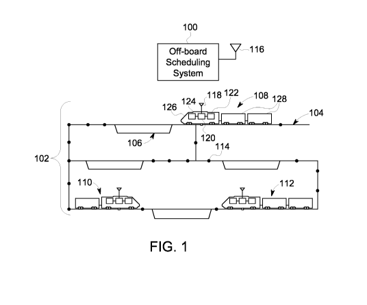
[0008] Figure 1 is a schematic view of one embodiment of an off-board
scheduling
system and a transportation network;
[0009] Figure 2 is a schematic diagram of one embodiment of the off-board
scheduling system shown in Figure 1;
2
CA 02860082 2014-06-20
WO 2013/101369 PCT/US2012/066252
[0010] Figure 3 is a schematic illustration of a powered rail vehicle in
accordance
with one embodiment;
[0011] Figure 4 is a flowchart of one embodiment of a method for
monitoring use of
an energy management system (EMS) by a vehicle traveling within a
transportation network;
and
[0012] Figure 5 is a flowchart of one embodiment of another method for
monitoring
use of an EMS by a vehicle traveling within a transportation network.
DETAILED DESCRIPTION
[0013] One or more embodiments of the inventive subject matter described
herein
provide systems and methods that monitor use of an energy management system
(EMS) by a
vehicle traveling within a transportation network of a plurality of routes.
The methods and
systems determine whether an EMS is available for use by the vehicle, which
may include
determining whether use of an EMS is allowed within a region of the
transportation network
within which the vehicle is located. Whether the EMS is being used by the
vehicle is also
determined. The information obtained by determining whether the EMS is
available for use
and/or whether the EMS is being used may be stored. A message may be sent to a
central
dispatch office and/or other off-board location associated with the
transportation network
when the EMS is not being used by the vehicle, for example when the EMS is not
being used
by the vehicle and the vehicle is within the region. The message may also
indicate a reason
why the EMS is not being used by the vehicle within the region.
[0014] The central dispatch office and/or other off-board location may
track use of
the EMS by one or more vehicles within the transportation network. For
example, the central
dispatch office may track use of the EMS by one or more vehicles over one or
more trips of
each of the one or more vehicles. The tracking information may be used by the
central
dispatch office in a variety of ways and for a variety of different purposes
and end goals. For
example, the tracking information may be used to evaluate one or more
operators of vehicles
within the transportation network, to allot the duties of vehicle operators or
other workers, to
revise a trip plan of one or more vehicles, and/or the like.
[0015] Figure 1 is a schematic view of one embodiment of a scheduling
system 100
and a transportation network 102. The transportation network 102 includes a
plurality of
3
CA 02860082 2014-06-20
WO 2013/101369 PCT/US2012/066252
interconnected routes 104, 106. In the illustrated embodiment, the routes 104,
106 represent
tracks, such as railroad tracks, that rail vehicles travel across. The routes
104 include main
line routes 104 and siding section routes 106. The transportation network 102
may extend
over a relatively large area, such as hundreds of square miles or kilometers
of land area. The
number of routes 104, 106 shown in Figure 1 is meant to be illustrative and
not limiting on
embodiments of the described subject matter. Moreover, while one or more
embodiments
described herein relate to a transportation network formed from rail tracks,
not all
embodiments are so limited. One or more embodiments may relate to
transportation
networks having main line routes that cannot be simultaneously traversed in
opposite
directions by different non-rail vehicles and siding section routes that are
connected with the
main line routes.
[0016] Plural separate vehicles 108, 110, 112 travel along the routes
104, 106. In the
illustrated embodiment, the vehicles 108, 110, 112 are shown and described
herein as rail
vehicles or rail vehicle consists. However, one or more other embodiments may
relate to
vehicles other than rail vehicles or rail vehicle consists. For example, the
vehicles may
represent other off-highway vehicles, automobiles (e.g., cars, busses, and the
like), marine
vessels, airplanes, and the like. A vehicle 108, 110, 112 may include a group
of powered
vehicles 126 (referring to rail vehicles configured for self propulsion, e.g.,
locomotives)
and/or non-powered vehicles 128 (referring to rail vehicles not configured for
self propulsion,
e.g., cargo or passenger cars) that are mechanically coupled or linked
together to travel along
the routes 104, 106. As shown in Figure 1, the main line routes 104 are
interconnected with
each other to permit the vehicles 108, 110, 112 to travel over various
combinations of the
routes 104 to move from a starting location to a destination location. The
main line routes
104 may be single track railway lines. For example, each of the main line
routes 104 may be
shared by vehicles 108, 110, 112 moving in opposite directions. In order to
avoid collisions
between vehicles 108, 110, 112 traveling in opposite directions toward each
other on a
common main line route 104 (such as the vehicles 110, 112 in Figure 1), the
siding section
route 106 may be connected with the main line route 104.
[0017] The siding section route 106 is an auxiliary portion of a route
that branches off
of the main line route 104. The siding section route 106 may be connected to
the main line
route 104 and may run parallel to the main line route 104 between two or more
locations
where the siding section route 106 is coupled with the main line route 104. In
one
4
CA 02860082 2014-06-20
WO 2013/101369 PCT/US2012/066252
embodiment, the siding section route 106 may be formed from lighter materials
or
construction such that the siding section route 106 may have lower speed
and/or weight limits
than the main line route 104. The siding section route 106 may be used by the
vehicles 108,
110, 112 to move off of the main line route 104 when another vehicle 108, 110,
112 is
approaching. For example, the vehicle 110 may move from the main route 104 to
the siding
section route 106 when a second rail vehicle 112 approaches along the same
main route 104.
The vehicle 110 can travel, slow down, and/or stop on the siding section route
106 until the
second rail vehicle 112 has passed on the main route 104. Once the second rail
vehicle 112
has passed, the first rail vehicle 110 can return to the main route 104.
[0018] In one embodiment, the vehicle 108, 110, 112 that moves to the
siding section
route 106 is referred to as a "yielding vehicle" or a "stopping vehicle," even
though the
vehicle 108, 110, 112 may not cease all movement on the siding section route
106. The
vehicle 108, 110, 112 that passes on the main route 104 while the yielding
vehicle 108, 110,
112 is on the siding section route 106 can be referred to as a "passing
vehicle." A "meet
event" represents a location and/or time at which the passing vehicle 108,
110, 112 and the
yielding vehicle 108, 110, 112 meet and pass each other. For example, a meet
event can
include the geographic location of the siding section route 106 and the time
at which the
passing vehicle 108, 110, 112 passes the geographic location of the siding
section route 106.
[0019] The vehicles 108, 110, 112 travel along the routes 104, 106
according to a
movement plan of the transportation network 102. The movement plan is a
logical construct
of the movement of the vehicles 108, 110, 112 moving through the
transportation network
102. For example, the movement plane may include a schedule for each of the
vehicles 108,
110, 112, with the schedules directing the vehicles 108, 110, 112 to move
along the routes
104, 106 at associated times. In one embodiment, the movement plan includes a
list, table, or
other logical arrangement of geographic locations (e.g., global positioning
system
coordinates) within the transportation network 102 and associated times. The
vehicles 108,
110, 112 move along various paths within the transportation network 102 to
arrive at the
geographic locations associated with the schedule of each vehicle 108, 110,
112 at the
specified times. The locations in the movement plan can be referred to as
"scheduled
waypoints" and the times at which the vehicles 108, 110, 112 are scheduled to
arrive or pass
the scheduled waypoints can be referred to as "scheduled times."
CA 02860082 2014-06-20
WO 2013/101369 PCT/US2012/066252
[0020] The movement plan can be based on starting locations and
destination
locations of the vehicles 108, 110, 112. For example, a schedule may be
developed for each
vehicle 108, 110, 112 that directs the vehicle 108, 110, 112 where and when to
move within
the transportation network 102 to arrive at a specified destination from the
starting location of
the vehicle 108, 110, 112. The schedules may include several scheduled
waypoints located
between the starting location and the destination location of the vehicle 108,
110, 112, along
with scheduled times for the scheduled waypoints. For example, a schedule may
include
several waypoints 114 located along a route between the starting location and
the destination
location of a vehicle 108, 110, 112.
[0021] The movement plan may be determined by the scheduling system 100.
As
shown in Figure 1, the scheduling system 100 can be disposed off-board (e.g.,
outside) of the
vehicles 108, 110, 112. For example, the scheduling system 100 may be disposed
at a central
dispatch office for a railroad company. The scheduling system 100 communicates
the
schedules of the vehicles 108, 110, 112. The scheduling system 100 can include
a wireless
antenna 116 (and associated transceiving equipment), such as a radio frequency
(RF) or
cellular antenna, that wirelessly transmits the schedules to the vehicles 108,
110, 112. For
example, the scheduling system 100 may transmit a different list of waypoints
114 and
associated scheduled times to each of the vehicles 108, 110, 112.
[0022] The vehicles 108, 110, 112 include wireless antennas 118, such as
RF or
cellular antennas, that receive the schedules from the scheduling system 100.
The wireless
antenna 118 communicates the received schedule to an energy management system
(EMS)
120 disposed on-board the vehicle 108, 110, 112. The EMS 120 may be embodied
in a
computer, computer processor, microcontroller, microprocessor, or other logic-
based device,
that operates based on one or more sets of instructions (e.g., software)
stored on a tangible
and non-transitory computer readable storage medium (e.g., hard drive, flash
drive, ROM, or
RAM). The EMS 120 may include a location determining device, such as a global
positioning system (GPS) device, that identifies a current location of the
vehicle 108, 110,
112 and a timing device, such as a clock, that determines a current time of
the vehicle 108,
110, 112. The EMS 120 can compare the current location and time of the vehicle
108, 110,
112 to the received schedule to determine if the vehicle 108, 110, 112 is
ahead of schedule
(e.g., is arriving at a scheduled waypoint 114 before an associated scheduled
time), behind
schedule (e.g., is arriving at a scheduled waypoint 114 after an associated
scheduled time), or
6
CA 02860082 2014-06-20
WO 2013/101369 PCT/US2012/066252
on time (e.g., is arriving at a scheduled waypoint 114 at a scheduled time or
within a
predetermined time period of the associated scheduled time).
[0023] Based on the comparison between the current location and time of
the vehicle
108, 110, 112 and the received schedule, the EMS 120 may generate control
instructions that
direct operation of a propulsion subsystem 122 of the respective vehicle 108,
110, 112. The
propulsion subsystem 122 can include one or more traction motors, brakes, and
the like, that
provide tractive effort to propel the vehicle 108, 110, 112 along the routes
104, 106 and
provide braking efforts to slow or stop movement of the vehicle 108, 110, 112.
The control
instructions may include commands that direct an operator of the vehicle 108,
110, 112 to
change or set the tractive effort and/or braking effort supplied by the
propulsion subsystem
122 of the vehicle 108, 110, 112, or commands that automatically change or set
the tractive
effort and/or braking effort. For example, if the vehicle 108, 110, 112 is
behind schedule, the
control instructions may reduce braking effort and/or increase tractive
effort. If the vehicle
108, 110, 112 is ahead of schedule, the control instructions may increase
braking effort
and/or reduce tractive effort.
[0024] In the illustrated embodiment, the EMS 120 determines a trip plan
that dictates
one or more operations of the propulsion subsystem 122 during a trip of the
corresponding
vehicle 108, 110, 112. A trip of the vehicle 108, 110, 112 includes the travel
of the vehicle
108, 110, 112 from a starting location to a destination location. The EMS 120
can refer to a
trip profile that includes information related to the vehicle 108, 110, 112,
the route or surface
on which the vehicle 108, 110, 112 travels, the geography over which the route
or surface
extends, and other information in order to form the trip plan. The trip plan
can be used to
control the propulsion subsystems of different powered rail vehicles in the
vehicle 108, 110,
or 112 to change the tractive efforts of the propulsion subsystems as the
vehicle 108, 110, 112
travels over different segments of the trip according to the trip plan.
[0025] For example, if the trip profile requires the vehicle 108, 110, or
112 to traverse
a steep incline and the trip profile indicates that the vehicle 108, 110, or
112 is carrying
significantly heavy cargo, then the EMS 120 may form a trip plan that directs
one or more of
the powered rail vehicles of the vehicle 108, 110, or 112 to increase the
tractive efforts
supplied by the respective propulsion subsystems. Conversely, if the vehicle
108, 110, or 112
is carrying a smaller cargo load based on the trip profile, then the EMS 120
may form a trip
plan that directs the propulsion subsystems to increase the supplied tractive
efforts by a
7
CA 02860082 2014-06-20
WO 2013/101369 PCT/US2012/066252
smaller amount than the tractive efforts would otherwise be increased if the
data indicated a
heavier cargo load. The trip plan may be formed according to other factors,
such as changes
in the route that the vehicle 108, 110, or 112 travels along, regulatory
requirements (e.g.,
emission limits) of the regions through which the vehicle 108, 110, or 112
travels, and the
like, and based on the trip profile. In one embodiment, the EMS 120 includes a
software
application such as the Trip OptimizerTM system provided by General Electric
Company, to
control propulsion operations of the vehicle 108, 110, or 112 during the trip
in order to reduce
fuel consumption of the powered rail vehicles, reduce emissions generated,
and/or to reduce
wear and tear on the vehicle 108, 110, 112.
[0026] The trip data used to form the trip profile may include vehicle
(e.g., train) data,
route data, and/or an update to trip data, vehicle data, or route data.
Vehicle (e.g., train) data
includes information about the vehicle and/or cargo being carried by the
vehicle. For
example, vehicle data may represent cargo content (such as information
representative of
cargo being transported by the vehicle) and/or vehicle information (such as
model numbers,
manufacturers, horsepower, and the like, of locomotives and/or other railcars
in the vehicle).
Route data may include information about an upcoming trip by the vehicle. By
way of
example, route data may include a trip profile of an upcoming trip of the
vehicle (e.g.,
information that can be used to control one or more operations of the vehicle,
such as tractive
and/or braking efforts provided during the powered units of a vehicle during
an upcoming
trip), station information (such as the location of a beginning station where
the upcoming trip
is to begin and/or the location of an ending station where the upcoming trip
is to end),
restriction information (such as work zone identifications, or information on
locations where
the route is being repaired or is near another route being repaired and
corresponding
speed/throttle limitations on the vehicle), and/or operating mode information
(such as
speed/throttle limitations on the vehicle in various locations, slow orders,
and the like).
Route data can include information about the route or rails upon which the
vehicle travels.
For example, the route data can include information about locations of damaged
sections of a
route, locations of route sections that are under repair or construction, the
curvature and/or
grade of a route, GPS coordinates of the route, and the like. The route data
is related to
operations of the vehicle as the route data includes information about the
route that the
vehicle is or will be traveling on. However, other types of data can be
recorded as the data
and/or the data may be used for other operations. The term "data" may refer to
trip data,
8
CA 02860082 2014-06-20
WO 2013/101369 PCT/US2012/066252
vehicle (e.g., train) data, and route data, only one of trip data, vehicle
data, or route data, or
another type of data.
[0027] In one embodiment, the vehicle 108, 110, 112 includes a display
device 124
that visually presents the control instructions to the operator on-board the
vehicle 108, 110,
112. For example, a computer monitor or display screen may present textual
settings for a
throttle or brake setting of the propulsion subsystem 122. The textual
settings prompt the
operator to change the tractive effort and/or braking effort of the propulsion
subsystem 122.
Alternatively, the control instructions may be communicated to the propulsion
subsystem 122
to automatically control the tractive effort and/or braking effort of the
propulsion subsystem
122. For example, the propulsion subsystem 122 may receive an updated throttle
or brake
setting from the EMS 120 and modify the tractive effort or braking effort in
response thereto.
[0028] Figure 2 is a schematic diagram of one embodiment of the off-board
scheduling system 100. The scheduling system 100 includes a processor 200
(e.g., a
computer processor, microprocessor, controller, microcontroller, or other
logic-based
computer device) that is communicatively coupled with a tangible and non-
transitory
computer readable storage medium 202, such as a computer hard drive, flash
drive, RAM,
ROM, EEPROM, and the like. The storage medium 202 includes one or more sets of
instructions that direct the processor 200 to perform various operations or
steps. For
example, the storage medium 202 can include software applications. In the
illustrated
embodiment, the sets of instructions are shown as a monitoring module 204, a
planning
module 206, a modification module 208, and a communication module 210.
Alternatively,
one or more of the monitoring module 204, the planning module 206, the
modification
module 208, and/or the communication module 210 may be embodied in a processor
similar
to the processor 200. For example, one or more of the modules 204, 206, 208,
210 may each
be a dedicated processor or application specific integrated circuit (ASIC).
[0029] An output device 212 is communicatively coupled with the processor
200.
The output device 212 presents information to an operator of the scheduling
system 100, such
as schedules of vehicles 108, 110, 112 (shown in Figure 1), adherence of the
vehicles 108,
110, 112 to the schedules, throughput parameters (described below) of the
transportation
network 102 (shown in Figure 1), and the like. By way of example, the output
device 212
may include a computer monitor, touchscreen, a printer, a speaker, and the
like. An input
device 214 is communicatively coupled with the processor 200. The input device
214
9
CA 02860082 2014-06-20
WO 2013/101369 PCT/US2012/066252
receives information from the operator and communicates the information to the
processor
200. The operator may control operation of the scheduling system 100 using the
input device
214. By way of example, the input device 214 may include a keyboard,
electronic mouse
device, stylus, touchscreen, microphone, and the like.
[0030] The monitoring module 204 monitors the vehicles 108, 110, 112
(shown in
Figure 1) as the vehicles 108, 110, 112 travel through the transportation
network 102 (shown
in Figure 1). The monitoring module 204 can track locations of the vehicles
108, 110, 112.
For example, each of the vehicles 108, 110, 112 may periodically transmit the
actual
locations and/or times at which the actual locations are determined to the
antenna 116 of the
scheduling system 100. The actual locations and times of the vehicles 108,
110, 112 can be
conveyed to the monitoring module 204 so that the monitoring module 204 can
determine
where the various vehicles 108, 110, 112 are located within the transportation
network 102.
[0031] In one embodiment, the planning module 206 determines the trip
plans for the
vehicles 108, 110, 112. For example, the planning module 206 can receive a
trip profile and
generate a trip plan of operational settings (e.g., throttle settings, brake
settings, speeds,
power output, and/or the like) for the vehicle as expressed as a function of
time and/or
distance along a trip. The vehicle can use the trip plan to set, control,
and/or recommend
actual operational settings of the vehicle. Different trip plans for different
vehicles and/or
different trips can be created. A combination of the trip plans and/or a
schedule of the
vehicle may be referred to herein as a movement plan of the transportation
network.
[0032] As the vehicles 108, 110, 112 (shown in Figure 1) travel in the
transportation
network 102 (shown in Figure 1), one or more vehicles 108, 110, 112 may
deviate from the
movement plan by moving ahead or behind in the associated schedules. For
example,
adverse weather conditions, degraded health of the vehicles, breakdowns,
and/or the like may
cause one or more vehicles to fall behind schedule. The modification module
208 can change
the trip plan for one or more of the vehicles. For example, if a vehicle is
too far behind
schedule, the modification module 208 can adjust the trip plan of the vehicle
or create a new
trip plan for the vehicle.
[0033] Figure 3 is a schematic illustration of a powered rail vehicle 700
in accordance
with one embodiment. The powered rail vehicle 700 may represent one or more of
the
powered rail vehicles 126 (shown in Figure 1) of the vehicles 108, 110, 112
(shown in Figure
CA 02860082 2014-06-20
WO 2013/101369 PCT/US2012/066252
1). The powered rail vehicle 700 includes an antenna 702 that may be similar
to the antenna
118 (shown in Figure 1), an energy management system (EMS) 704 that may be
similar to
the EMS 120 (shown in Figure 1), a propulsion subsystem 706 that may be
similar to the
propulsion subsystem 122 (shown in Figure 1), and a display device 708 that
may be similar
to the display device 124 (shown in Figure 1).
[0034] In the illustrated embodiment, the powered rail vehicle 700
includes a
communication device 710 that is communicatively coupled with the antenna 702
for
communicating data with off-board components. For example, the communication
device
710 can include a transceiver device that wirelessly transmits and receives
data messages,
such as updated meet events from the scheduling system 100 (shown in Figure
1). The
communication device 710 conveys the data to one or more of the display device
708 for
presentation of the data to the operator of the powered rail vehicle 700, to
the EMS 704 for
use in determining tractive efforts and/or braking efforts to be provided by
the powered rail
vehicle 700, to a computer readable storage medium ("memory 714") of the
powered rail
vehicle 700, and/or to a control unit 712 of the powered rail vehicle 700.
[0035] The memory 714 may include a tangible and non-transitory computer
readable
storage medium, such as a computer hard drive, flash drive, RAM, ROM, EEPROM,
and the
like. The memory 714 can include one or more sets of instructions that direct
the control unit
712 to perform various operations or steps. For example, the memory 714 can
include
software applications.
[0036] The control unit 712 may represent a hardware and/or software
system that
operates to perform one or more functions to control operations of the powered
rail vehicle
700. For example, the control unit 712 may include one or more computer
processors,
controllers, or other logic-based devices that perform operations based on
instructions stored
on a tangible and non-transitory computer readable storage medium, such as the
memory 714,
for controlling tractive efforts and/or braking efforts of the powered rail
vehicle 700.
Alternatively, the control unit 712 may include a hard-wired device that
performs operations
based on hard-wired logic of the device. The control unit 712 shown in Figure
3 may
represent the hardware that operates based on software or hardwired
instructions, the
software that directs hardware to perform the operations, or a combination
thereof.
11
CA 02860082 2014-06-20
WO 2013/101369 PCT/US2012/066252
[0037] The control unit 712 can receive data messages from the scheduling
system
100 (shown in Figure 1) via the communication device 710 and use information
included in
the data messages to control or change tractive efforts and/or braking efforts
of the powered
rail vehicle 700 based on the information. For example, the control unit 712
may receive trip
plans and/or updated trip plans from the scheduling system 100.
[0038] In one embodiment, the scheduling system 100 sends a scheduled
destination
and/or a scheduled arrival time to the EMS 704, and the EMS 704 generates the
trip plan for
the vehicle based on the information received from the scheduling system 100.
The EMS 704
conveys the trip plan that is formed for a vehicle that includes the powered
rail vehicle 700 to
the control unit 712. As described above, the trip plan may be formed based on
a trip profile
for the vehicle and may dictate tractive efforts and/or braking efforts for
different portions of
the trip. The EMS 704 may update the trip plan when an updated schedule
information is
received from the scheduling system 100 (shown in Figure 1). For example, if
an updated
destination and/or updated arrival time is received from the scheduling system
100, then the
EMS 704 may revise the trip plan to require lower speed and/or tractive
efforts from the
powered rail vehicles in the vehicle to arrive at a later time for the updated
event than the
original time and/or to arrive at a closer location for the updated meet event
than the original
location.
[0039] The trip plan may include control instructions for controlling
(e.g., setting,
maintaining, changing, and/or the like) the tractive effort and/or braking
effort of the
propulsion subsystem 706. The control unit 712 can receive the trip plan from
the EMS 704
and automatically control the tractive effort and/or braking effort of the
propulsion subsystem
706 accordingly using the control instructions of the trip plan. For example,
if the updated
trip plan dictates that a lower speed is to be used to arrive at the updated
meet event, then the
control unit 712 can direct the propulsion subsystem 706 to reduce the
tractive effort
provided by the propulsion subsystem 706. Alternatively, the control unit 712
uses the
control instructions provided within the trip plan to indicate (e.g., using a
display, audible
indications, and/or the like) control commands that direct an operator of the
vehicle 700 to
control the tractive effort and/or braking effort supplied by the propulsion
subsystem 706.
[0040] Figure 4 is flowchart of one embodiment of a method 550 for
monitoring use
of an EMS by a vehicle traveling within a transportation network. The method
550 may be
preformed by a system including a control unit, an EMS, and/or an off-board
location (e.g.,
12
CA 02860082 2014-06-20
WO 2013/101369 PCT/US2012/066252
the central dispatch office of the transportation network). For example, the
method 550 may
be preformed by a system that includes the control unit 712 (Figure 3), the
EMS 120 (Figure
1) and/or the EMS 704 (Figure 3), and/or the central dispatch office
associated with the
transportation network 102 (Figure 1). The central dispatch office may include
a facility
where the scheduling system 100 is located, or may be another facility that is
remote from
(e.g., off-board) the vehicle. Although the method 550 is described herein
with respect to the
central dispatch office, it should be understood that any other off-board
location may be used.
The method 550 may be used to monitor use of an EMS by a vehicle within the
transportation
network. For example, the method 550 may be used to monitor use of the EMS 120
of at
least one of the vehicles 108, 110, 112 (Figure 1) and/or the EMS 704 of the
vehicle 700
(Figure 3). For exemplary purposes only, the method 550 will be described
herein with
reference to the vehicle 700 traveling within the transportation network 102.
Although the
EMS 704 is shown as being located on-board the vehicle 700, the EMS 704 may be
additionally or alternatively located at the central dispatch office and/or
another location off-
board the vehicle 700.
[0041] At 552, the method 550 includes determining whether the EMS 704 is
available for use by the vehicle 700. By "available for use", it is meant that
the EMS 704 is
capable of being used by the vehicle 700. For example, the EMS 704 may be
capable of
being used by the vehicle 700 when the EMS 704 is on-line (e.g., in a powered,
or on, state).
Optionally, the determining step 552 includes determining at 552a whether the
EMS 704 is
on-line. Moreover, and for example, the EMS 704 may be capable of being used
by the
vehicle 700 when the EMS 704 is off-line (e.g., in an unpowered, or off,
state) but is capable
of being changed to be on-line. The determining step 552 optionally includes
determining at
552b whether the EMS 704 is capable of being changed from being off-line to
being on-line.
The method 550 may include indicating to the vehicle operator on a display
(e.g., the display
device 708) that the EMS 704 is currently off-line but is currently capable of
being changed
from being off-line to being on-line. In addition or alternative to such an
indication, the
method 550 may include prompting the vehicle operator to change the EMS 704
from being
off-line to being on-line, for example by displaying text and/or another
graphic, using an
audible prompt, and/or the like.
[0042] Optionally, the determining step 552 includes determining, at
552c, whether
use of the EMS 704 of the vehicle 700 is allowed within a region of the
transportation
13
CA 02860082 2014-06-20
WO 2013/101369 PCT/US2012/066252
network 102 within which the vehicle 700 is located. The region may be any
region within
the transportation network 102 and includes a segment of a trip (e.g., a
segment of a
movement plan) of the vehicle 700 within the transportation network 102.
Determining at
552c whether use of the EMS 704 is allowed within a particular region may
include first
determining at 552ca a location of the vehicle 700 within the transportation
network 102.
The determining step 552c may further include identifying at 552cb the region
of the
transportation network 102 within which the vehicle 700 is currently located.
The
determination at 552c as to whether use of the EMS 704 is allowed within a
particular region
may be performed upon entrance of the vehicle 700 into the region or a
predetermined
amount of time after the vehicle 700 has entered the region. In one
embodiment, the system
is prompted to determine at 552c whether use of the EMS 704 is allowed within
the region
upon movement of the vehicle 700 out of a region within which use of the EMS
704 is
prohibited (i.e., not allowed).
[0043] The determination at 552c of whether use of the EMS 704 is allowed
within
the region may be performed using any method, information, comparison, and/or
the like.
For example, determining at 552c may include comparing the location (e.g., the
approximate
exact location of the vehicle 700 within the transportation network 102, the
region within
which the vehicle 700 is located, and/or the location of the vehicle 700
within the region) of
the vehicle 700 within the transportation network 102 to a route chart of the
EMS 704 to
determine whether the region is a region within which use of the EMS is
currently allowed.
Regions within which use of the EMS 704 is allowed may be identified within
the route chart
as "energy management regions".
[0044] Use of the EMS 704 within a particular region may be prohibited
for a variety
of reasons, such as, but not limited to, ambient weather conditions within the
region, the
orientation, structure, path, and/or the like of the route (e.g., the routes
104, 106), a
configuration issue with the EMS 704, and/or the like. For example, use of the
EMS 704
during some ambient weather conditions may cause unsafe operation of the
vehicle 700. In
other words, and for example, some ambient conditions may require that the
operator
manually (e.g., without following any control commands) control operation of
the vehicle
700 to prevent the loss or reduction of control of the vehicle. Moreover, and
for example, the
EMS 704 may have a configuration issue that prevents proper operation of the
EMS 704
and/or prevents adequate control of the vehicle 700. Configuration issues
include, but are not
14
CA 02860082 2014-06-20
WO 2013/101369 PCT/US2012/066252
limited to, a malfunction or other fault of the EMS 704, one or more over
speeds and/or under
speeds, an out of date software version of the EMS 704, and/or the like.
Another example of
a configuration issue of the EMS 704 is an EMS that is not configured to
control the brakes
of the vehicle 700, wherein use of the EMS 704 may not be allowed in regions
that have
downwardly sloped grades. The orientation, structure, path, and/or the like of
the route (e.g.,
a grade, turning radius, and/or the like) within a region may cause unsafe
operation of the
vehicle 700 when the EMS 704 is used. Such regions may be referred to as
"yellow zones"
or "manual control zones", wherein the operator manually controls operation of
the vehicle
700.
[0045] The determination at 552c may be included within the method 550 in
addition
or alternatively to the steps 552a and/or 552b. In one embodiment, the control
unit 712 is
configured to perform some or all of the determining step 552 (including some
or all of the
steps 552a, 552b, 552c, 552ca, and/or 552cb). But, one or more other
components may be
provided in addition or alternative to the control unit 712 for performing
some or all of the
determining step 552 (including some or all of the steps 552a, 552b, 552c,
552ca, and/or
552cb). In one embodiment, one or more of the component(s) used to perform
some or all of
the determining step 552 (including some or all of the steps 552a, 552b, 552c,
552ca, and/or
552cb) is located off-board the vehicle 700.
[0046] If it is determined at 552 that the EMS 704 is available for use
by the vehicle
700, the method 550 includes, at 554, determining whether the EMS 704 is being
used by the
vehicle 700. For example, if it is determined at 552c that use of the EMS 704
is allowed
within the region, the determination at 554 may include determining, at 554a,
whether the
EMS 704 is being used by the vehicle 700 when the vehicle 700 is within the
region. As
used herein, the EMS 704 is being "used by the vehicle" when: the trip plan of
the EMS 704
is used to automatically control the propulsion subsystem 706 of the vehicle
700; or when an
operator of the vehicle 700 is following one or more control commands within a
predetermined threshold.
[0047] The determination at 554a may be made using any method,
information,
comparison, and/or the like. For example, in one embodiment, determining 554
whether the
EMS 704 is being used by the vehicle 700 includes determining whether a trip
plan of the
EMS 704 is being followed by the vehicle 700. Moreover, and for example,
determining 554
whether the EMS 704 is being used by the vehicle 700 may include determining
whether an
CA 02860082 2014-06-20
WO 2013/101369 PCT/US2012/066252
operator of the vehicle 700 is following one or more control commands within a
predetermined threshold.
[0048] In one embodiment, the control unit 712 is configured to perform
some or all
of the determining step 554 (including some or all of the step 554a). But, one
or more other
components may be provided in addition or alternative to the control unit 712
for performing
some or all of the determining step 554 (including some or all of the step
554a). In one
embodiment, one or more of the component(s) used to perform some or all of the
determining
step 554 (including some or all of the step 554a) is located off-board the
vehicle 700.
[0049] The method 550 optionally includes storing, at 556, the
information obtained
from the determination steps 552 and/or 554. For example, storing at 556 may
include
storing the results of the determination step 552 (e.g., storing whether the
EMS 704 was
available for use by the vehicle 700 at one or more specific times and/or
within one or more
time periods). Moreover, and for example, the storing step 556 may include
storing the
results of the determination step 554, which may include, for example, storing
whether the
EMS 704 was being used by the vehicle 700 at one or more specific times and/or
within one
or more time periods when the EMS 704 was available for use by the vehicle
700. Storing
the results of the determination step 554 may additionally or alternatively
include storing the
results of the determination step 554a (e.g., storing whether the EMS 704 was
being used by
the vehicle 700 when the vehicle 700 was within one or more regions wherein
use of the
EMS 704 was allowed).
[0050] Some or all of the information stored at 556 may be stored on-
board the
vehicle 700 (e.g., in the memory 714), and/or some or all of the information
stored at 556
may be stored off-board the vehicle 700 (e.g., at the central dispatch office
and/or other off-
board location). The information stored at 556 may be used by the vehicle 700,
the central
dispatch office and/or other off-board location, and/or one or more other
components in a
variety of ways and for a variety of different purposes and end goals, such
as, but not limited
to, evaluating one or more operators of vehicles 700 within the transportation
network 102,
allotting the duties of vehicle operators or other workers, revising a trip
plan of one or more
vehicles 700, and/or the like. The information stored at 556 may be used to
increase an
efficiency (e.g., reduce fuel consumption) of the transportation network 102,
for example of
one or more trips of one or more vehicles 700. The information stored at 556
may be used to
reduce the emissions generated by vehicles 700 and/or to reduce the amount of
fatigue
16
CA 02860082 2014-06-20
WO 2013/101369 PCT/US2012/066252
experienced by components of vehicles 700 (e.g., to provide components of a
vehicle 700
with a longer life span).
[0051] The method 550 optionally includes sending, at 558, a message to
the central
dispatch office and/or other off-board location that the EMS 704 is not being
used by the
vehicle 700 when the EMS 704 is available for use by the vehicle 700. For
example, if it is
determined at 554a that the EMS 704 is not being used by the vehicle 700
within a region
within which use of the EMS 704 is allowed, sending a message at 558 may
include sending,
at 558a, a message to the central dispatch office and/or other off-board
location that the EMS
704 is not being used by the vehicle 700 within the region.
[0052] A message may be sent at 558 at any point(s) in time when the EMS
704 is
available for use by the vehicle 700 but is not being used by the vehicle 700.
For example, a
message may be sent at 558a upon entry of the vehicle 700 into the region
(within which use
of the EMS 704 is allowed) and completion of the determining steps 552 and
554. But, the
message sent at 558 (including any message sent at 558a) may alternatively be
sent with a
delay. For example, sending the message sent at 558 may include waiting a
predetermined
amount of time after it has been determined at 554 that the EMS 704 is not
being used but is
available to send at 558 the message. Moreover, and for example, sending the
message at
558a may include waiting a predetermined amount of time after the vehicle 700
has entered
the region to send at 558a the message. The delay may give an operator the
chance to initiate
use of the EMS 704 once the operator realizes that the EMS 704 is available
for use. For
example, the delay may give an operator the chance to initiate use the EMS 704
after the
vehicle 700 has entered the region and once the operator realizes that use of
the EMS within
the region is allowed. The message sent at 558a may indicate to the central
dispatch office
and/or other off-board location that the EMS 704 is allowed for use within the
region that the
vehicle 700 is within.
[0053] Whether in response to the determination step 554a and/or the
sending step
558a, the method 550 may include indicating to a vehicle operator on a display
(e.g., the
display device 708) that the EMS 704 is not currently being used but is
allowed for use
within the region that vehicle 700 is traveling within. The method 550 may
additionally or
alternatively include prompting the vehicle operator to initiate use of the
EMS 704 when the
EMS 704 is allowed for use but is not currently being used. For example, the
display may
prompt the vehicle operator by displaying text or another graphic. In addition
or
17
CA 02860082 2014-06-20
WO 2013/101369 PCT/US2012/066252
alternatively, the prompt may be an audible prompt output by the display
and/or another
device.
[0054] Optionally, sending the message at 558a may include indicating at
558aa one
or more reasons why the EMS 704 is not being used by the vehicle 700 within
the region.
The indication at 558aa may be within the message that the EMS 704 is not
being used by the
vehicle 700 within the region, or may be contained within another message sent
to the central
dispatch office and/or other off-board location. The reason(s) may be any
reason, such as,
but not limited to, the region is a yellow or manual control region, ambient
weather
conditions within the region, the orientation, structure, path, and/or the
like of the route (e.g.,
the routes 104, 106), a configuration issue with the EMS 704, an operator
selection, and/or
the like.
[0055] In one embodiment, the method 550 includes enabling at 558ab the
operator of
the vehicle 700 to select one or more reasons why the EMS 704 is not being
used within the
region. For example, the display may display a list of one or more reasons
that the operator
can select using the display (e.g., a touch screen) and/or an input device
(e.g., a mouse, a
keyboard, a pointer, and/or the like). In addition or alternatively, the
operator may use the
display and/or an input device to compose one or more reasons. The reason(s)
selected or
composed by the operator may be any reason, such as, but not limited to, the
region is a
yellow or manual control region, ambient weather conditions within the region,
the
orientation, structure, path, and/or the like of the route (e.g., the routes
104, 106), a
configuration issue with the EMS 704, and/or the like. For example, in some
situations the
central dispatch office and/or other off-board location may not know that a
region is a yellow
or manual control zone, in which case the operator may select such a reason
for not using the
EMS 704. Moreover, and for example, even in regions within which use of the
EMS 704 is
allowed by the central dispatch office and/or other off-board location, the
operator may feel
that the ambient weather conditions and/or the orientation, structure, path,
and/or the like of
the route within the region will result in unsafe operation of the vehicle 700
using the EMS
704. In such situations, the operator may desire to manually control operation
of the vehicle
instead of using the EMS 704.
[0056] In one embodiment, the control unit 712 is configured to perform
some or all
of the sending step 558 (including some or all of the steps 558a, 558aa,
and/or 558ab). But,
one or more other components may be provided in addition or alternative to the
control unit
18
CA 02860082 2014-06-20
WO 2013/101369 PCT/US2012/066252
712 for performing the some or all of the sending step 558 (including some or
all of the steps
558a, 558aa, and/or 558ab. In one embodiment, the component(s) used to perform
some or
all of the sending step 558 (including some or all of the steps 558a, 558aa,
and/or 558ab) is
located off-board the vehicle 700.
[0057] As briefly described above, the central dispatch office and/or
other off-board
location may track use of an EMS by one or more vehicles within a
transportation network.
Figure 5 is flowchart of one embodiment of another method 650 for monitoring
use of an
EMS by a vehicle traveling within a transportation network. The method 650 may
be
preformed by a system including a control unit, an EMS, and/or an off-board
location (e.g.,
the central dispatch office of the transportation network). For example, the
method 650 may
be preformed by a system that includes the control unit 712 (Figure 3), the
EMS 120 (Figure
1) and/or the EMS 704 (Figure 3), and/or the central dispatch office
associated with the
transportation network 102 (Figure 1). Although the method 650 is described
herein with
respect to the central dispatch office, it should be understood that any other
off-board location
may be used. The method 650 may be used to monitor use of an EMS by any
vehicle within
any transportation network. For example, the method 650 may be used to monitor
use of the
EMS 120 of at least one of the vehicles 108, 110, 112 (Figure 1) and/or the
EMS 704 of the
vehicle 700 (Figure 3). For exemplary purposes only, the method 650 will be
described
herein with reference to the vehicle 700 traveling within the transportation
network 102.
[0058] At 652, the method 650 includes receiving a message at a central
dispatch
office and/or other off-board location associated with the transportation
network 102. The
message received at 652 indicates that the EMS 704 of the vehicle 700, which
is or was
traveling along a trip within the transportation network 102, is currently or
was previously
available for use by the vehicle 700 but is/was not being used by the vehicle
700 during such
availability. For example, the message received at 652 may indicate that the
EMS 704 of the
vehicle is not being used by the vehicle 700 when the vehicle 700 is within a
region of the
transportation network 102 within which use of the EMS 704 is allowed.
Moreover, and for
example, the message received at 652 may indicate that the EMS 704 of the
vehicle was not
being used by the vehicle 700 when the vehicle 700 was within a region within
which use of
the EMS 704 is allowed. The message may be received at 652 from the vehicle
700, for
example as described above with respect to the method 550 (Figure 4). The
message
received at 652 may indicate that the EMS 704 is allowed to be used within a
region within
19
CA 02860082 2014-06-20
WO 2013/101369 PCT/US2012/066252
which the vehicle 700 was or is currently traveling. At 654, the method 650
further includes
tracking, for example at the central dispatch office and/or other off-board
location, use of the
EMS 704 by the vehicle 700 as the vehicle 700 travels within the
transportation network 102
along the route of the trip. In one alternative embodiment, the receiving
and/or tracking steps
652 and 654, respectively, are preformed on-board one or more vehicles 700 in
addition or
alternative to being performed at the central dispatch office and/or other off-
board location.
[0059] The tracking performed at step 654 generates tracking information
related to
use of the EMS 704 by one or more vehicles 700 during one or more trips of the
vehicle(s)
700 within the transportation network 102. The tracking information generated
may be for a
single trip of a single vehicle 700. Alternatively, the tracking information
generated may be
for a plurality of trips of a single vehicle 700, or may be for a plurality of
vehicles (each
having at least one trip). Accordingly, the receiving step 652 may include
receiving one or
more messages for a single trip of a single vehicle 700, may include receiving
one or more
messages for each of a plurality of trips of a single vehicle 700, or may
include receiving one
or more messages for at least one trip of a plurality of vehicles 700.
[0060] The tracking information may be used by the central dispatch
office and/or
one or more other components in a variety of ways and for a variety of
different purposes and
end goals, such as, but not limited to, evaluating one or more operators of
vehicles 700 within
the transportation network 102, allotting the duties of vehicle operators or
other workers,
revising a trip plan of one or more vehicles 700, and/or the like. The
tracking information
may be used to increase an efficiency (e.g., reduce fuel consumption) of the
transportation
network 102, for example of one or more trips of one or more vehicles 700. The
tracking
information may be used to reduce the emissions generated by the vehicle 700
and/or to
reduce the amount of fatigue experienced by components of the vehicle 700
(e.g., to provide
components of the vehicle 700 with a longer life span).
[0061] One example increasing an efficiency of a trip of a vehicle 700
includes
analyzing the tracking information to determine the regions within a trip
where the EMS 704
was allowed for use but the EMS 704 was nevertheless not used. The trip plan
of the EMS
704 for a particular trip can be revised according to the tracking
information. Specifically,
the tracking information can be utilized to better utilize the EMS 704 and
thereby improve
the trip plan to provide the propulsion sub-system 706 of the vehicle 700 with
an increased
efficiency (e.g., a reduce fuel consumption) over the length of the trip plan.
The increased
CA 02860082 2014-06-20
WO 2013/101369 PCT/US2012/066252
efficiency may result in lower operating costs of the vehicle 700, less
emissions generated by
the vehicle 700, and/or less fatigue of components of the vehicle 700 (e.g.,
to provide
components of the vehicle 700 with a longer life span). When applied over a
relatively large
number of vehicles within a relatively large transportation network,
efficiency gains may
significantly reduce the cost of operating the vehicles within the
transportation network.
Moreover, and for example, the tracking information can be used to alter the
orientation,
structure, path, and/or the like of one or more routes, for example in regions
where the EMS
704 is not used often or at all (whether or not use of the EMS 704 is allowed
in such regions).
For example, the tracking information can be utilized to change the
orientation, structure,
path, and/or the like of one or more routes such that a vehicle operator is
more likely to use
the EMS 704 within the region, which may increase an efficiency (e.g., reduce
fuel
consumption) of the vehicle 700.
[0062] Another example of increasing an efficiency of the transportation
network 102
includes using the tracking information to allot the duties of vehicle
operators or other
workers within the transportation network 102. For example, the tracking
information may
indicate that a particular operator performs better (e.g., is more efficient,
such as, but not
limited to, reduce fuel consumption, reduce emissions, and/or the like) on
particular types of
and/or specific routes within the transportation network 102 as compared with
other types
and/or specific routes within the network 102. The tracking information can
thus be used to
allot to the operator the specific and/or types of routes on which the
operator performs best.
The allotment of routes to a plurality of various operators can thus be
improved to provide the
transportation network 102 with an increased efficiency.
[0063] In one embodiment, a method (e.g., a method for monitoring use of
an energy
management system (EMS)) includes determining whether use of an energy
management
system (EMS) associated with a vehicle traveling in a transportation network
is allowed
within a region of the transportation network. The EMS obtains a trip plan for
the vehicle
that designates operational settings of the vehicle as a function of at least
one of distance or
time along a trip of the vehicle. The method also includes determining whether
the EMS is
being used by the vehicle when the vehicle is within the region, and sending a
message to an
off-board location when the EMS is not being used by the vehicle within the
region.
21
CA 02860082 2014-06-20
WO 2013/101369 PCT/US2012/066252
[0064] In another aspect, sending a message to the off-board location
includes
indicating to the off-board location a reason why the EMS is not being used by
the vehicle
within the region.
[0065] In another aspect, determining whether use of the EMS is allowed
within the
region includes determining a location of the vehicle within the
transportation network and
within the region.
[0066] In another aspect, determining whether use of the EMS is allowed
within the
region includes comparing a location of the vehicle within the transportation
network to a
route chart of the EMS to determine whether the region is an energy management
region.
[0067] In another aspect, determining whether the EMS is being used by
the vehicle
includes determining whether an operator is following at least one command
instruction
within a predetermined threshold during.
[0068] In another aspect, determining whether the EMS is being used by
the vehicle
includes determining whether the trip plan of the EMS is being followed by the
vehicle when
the vehicle is within the region.
[0069] In another aspect, sending the message to the , the location of
the vehicle
being includes waiting a predetermined amount of time after the vehicle has
entered the
region to send the message.
[0070] In another aspect, the method includes displaying to an operator
of the vehicle
that the EMS is allowed for use but is not being used when the vehicle is
within the region.
[0071] In another aspect, the method includes prompting an operator of
the vehicle to
initiate use of the EMS when the EMS is allowed for use and the vehicle is
within the region.
[0072] In another aspect, sending the message to the off-board location
includes
indicating to the off-board location that the EMS is allowed for use within
the region.
[0073] In another aspect, sending the message to the off-board location
includes
indicating to the off-board location that the EMS is not being used by the
vehicle within the
region because of ambient conditions within the region.
22
CA 02860082 2014-06-20
WO 2013/101369 PCT/US2012/066252
[0074] In another aspect, sending the message to the off-board location
includes
indicating to the off-board location that the EMS is not being used by the
vehicle within the
region because of a configuration issue with the EMS.
[0075] In another aspect, the method includes enabling an operator of the
vehicle to
select a reason why the EMS is not being used within the region, wherein
sending the
message to the off-board location includes indicating to the off-board
location that the EMS
is not being used by the vehicle within the region because of the reason
selected by the
operator.
[0076] In another aspect, the trip plan designates the operational
settings for the
vehicle in order to reduce at least one of fuel consumed or emissions
generated during the trip
relative to traveling according to another plan.
[0077] In another embodiment, a method (e.g., a method for monitoring use
of an
energy management system (EMS)) includes receiving a message at an off-board
location.
The message indicates that an energy management system (EMS) associated with a
vehicle
traveling along a trip within a transportation network is not being used by
the vehicle when
the vehicle is within a region of the transportation network. The EMS uses a
trip plan of
operational settings for the vehicle. The method also includes tracking, at
the off-board
location, use of the EMS by the vehicle as the vehicle travels along the trip
within the
transportation network.
[0078] In another aspect, the message received at the off-board location
further
indicates that the EMS is allowed to be used within the region.
[0079] In another aspect, receiving the message at the off-board location
includes
receiving the message from the vehicle.
[0080] In another aspect, receiving the message includes receiving at
least one
message for each of a plurality of trips of the vehicle.
[0081] In another aspect, receiving the message includes receiving at
least one
message for at least one trip of each of a plurality of vehicles.
[0082] In another aspect, tracking the use of the EMS includes tracking
use of the
EMS for a plurality of trips of the vehicle.
23
CA 02860082 2014-06-20
WO 2013/101369 PCT/US2012/066252
[0083] In another aspect, tracking the use of the EMS includes tracking
use of the
EMS for at least one trip of each of a plurality of vehicles.
[0084] In another aspect, the method includes evaluating an operator of
the vehicle
based on tracking of the use of the EMS.
[0085] In another aspect, the method includes allotting duties of vehicle
operators
based on tracking of the use of the EMS.
[0086] In another aspect, the method includes revising the trip plan of
the vehicle
based on tracking of the use of the EMS.
[0087] In another embodiment, a system (e.g., a system including a
control unit, an
energy management system (EMS), and/or an off-board location) includes an
energy
management system (EMS) associated with a vehicle that is configured to travel
in a
transportation network. The EMS is configured to use a trip plan of
operational settings for
the vehicle. The system also includes a control unit for the vehicle. The
control unit is
configured to control operation of the vehicle and is operatively connected to
the EMS. The
control unit is configured to determine whether the EMS is available for use
by the vehicle,
determine whether the EMS is being used by the vehicle, and store information
obtained from
the determination of whether the EMS is being used by the vehicle.
[0088] In another aspect, the control unit is configured to determine
whether the EMS
is available for use by the vehicle by determining whether the EMS is on-line.
[0089] In another aspect, the control unit is configured to determine
whether the EMS
is being used by the vehicle by determining whether a trip plan of the EMS is
being followed
by the vehicle.
[0090] In another aspect, the control unit is configured to determine
whether the EMS
is being used by the vehicle by determining whether an operator of the vehicle
is following at
least one control command within a predetermined threshold.
[0091] In another aspect, the control unit is configured to store
information by storing
whether the EMS was available for use by the vehicle at at least one of at
least one specific
time or within at least one time period.
24
CA 02860082 2014-06-20
WO 2013/101369 PCT/US2012/066252
[0092] In another aspect, the control unit is configured to store
information by storing
whether the EMS was being used by the vehicle at at least one of at least one
specific time or
within at least one time period when the EMS was available for use by the
vehicle.
[0093] In another aspect, the control unit is configured to store
information on-board
the vehicle.
[0094] In another embodiment, a method (e.g., a method for monitoring use
of an
energy management system (EMS)) includes determining whether an energy
management
system (EMS) associated with a vehicle traveling in a transportation network
is available for
use by the vehicle. The EMS obtains a trip plan for the vehicle that
designates operational
settings of the vehicle as a function of at least one of distance or time
along a trip of the
vehicle. The method also includes determining whether the EMS is being used by
the
vehicle, and storing information obtained from the determination of whether
the EMS is
being used by the vehicle.
[0095] In another aspect, determining whether the EMS is available for
use by the
vehicle includes determining whether the EMS is on-line.
[0096] In another aspect, determining whether the EMS is available for
use by the
vehicle includes determining whether use of the EMS is allowed within a region
of the
transportation network.
[0097] In another aspect, determining whether the EMS is being used by
the vehicle
includes determining whether a trip plan of the EMS is being followed by the
vehicle.
[0098] In another aspect, determining whether the EMS is being used by
the vehicle
includes determining whether an operator of the vehicle is following at least
one control
command within a predetermined threshold.
[0099] In another aspect, determining whether the EMS is being used by
the vehicle
includes determining whether the EMS is being used by the vehicle within a
region of the
transportation network within which use of the EMS is allowed.
[00100] In another aspect, storing information includes storing whether
the EMS was
available for use by the vehicle at at least one of at least one specific time
or within at least
one time period.
CA 02860082 2014-06-20
WO 2013/101369 PCT/US2012/066252
[00101] In another aspect, storing information includes storing whether
the EMS was
being used by the vehicle at at least one of at least one specific time or
within at least one
time period when the EMS was available for use by the vehicle.
[00102] In another aspect, storing information includes storing whether
the EMS was
being used by the vehicle when the vehicle was within at least one region of
the
transportation network wherein use of the EMS was allowed.
[00103] In another aspect, storing information includes storing the
information on-
board the vehicle.
[00104] In another aspect, the method further includes sending a message
to an off-
board location when the EMS is available for use but is not being used by the
vehicle.
[00105] It is to be understood that the above description is intended to
be illustrative,
and not restrictive. For example, the above-described embodiments (and/or
aspects thereof)
may be used in combination with each other. In addition, many modifications
may be made
to adapt a particular situation or material to the teachings of the inventive
subject matter
without departing from its scope. While the dimensions and types of materials
described
herein are intended to define the parameters of the inventive subject matter,
they are by no
means limiting and are exemplary embodiments. Many other embodiments will be
apparent
to one of ordinary skill in the art upon reviewing the above description. The
scope of the
inventive subject matter should, therefore, be determined with reference to
the appended
claims, along with the full scope of equivalents to which such claims are
entitled. In the
appended claims, the terms "including" and "in which" are used as the plain-
English
equivalents of the respective terms "comprising" and "wherein." Moreover, in
the following
claims, the terms "first," "second," and "third," etc. are used merely as
labels, and are not
intended to impose numerical requirements on their objects. Further, the
limitations of the
following claims are not written in means-plus-function format and are not
intended to be
interpreted based on 35 U.S.C. 112, sixth paragraph, unless and until such
claim limitations
expressly use the phrase "means for" followed by a statement of function void
of further
structure.
[00106] This written description uses examples to disclose several
embodiments of the
inventive subject matter, including the best mode, and also to enable one of
ordinary skill in
the art to practice the embodiments of inventive subject matter, including
making and using
26
CA 02860082 2014-06-20
WO 2013/101369 PCT/US2012/066252
any devices or systems and performing any incorporated methods. The patentable
scope of
the inventive subject matter is defined by the claims, and may include other
examples that
occur to one of ordinary skill in the art. Such other examples are intended to
be within the
scope of the claims if they have structural elements that do not differ from
the literal language
of the claims, or if they include equivalent structural elements with
insubstantial differences
from the literal languages of the claims.
[00107] The foregoing description of certain embodiments of the present
inventive
subject matter will be better understood when read in conjunction with the
appended
drawings. To the extent that the figures illustrate diagrams of the functional
blocks of various
embodiments, the functional blocks are not necessarily indicative of the
division between
hardware circuitry. Thus, for example, one or more of the functional blocks
(for example,
processors or memories) may be implemented in a single piece of hardware (for
example, a
general purpose signal processor, microcontroller, random access memory, hard
disk, and the
like). Similarly, the programs may be stand alone programs, may be
incorporated as
subroutines in an operating system, may be functions in an installed software
package, and
the like. The various embodiments are not limited to the arrangements and
instrumentality
shown in the drawings.
[00108] As used herein, an element or step recited in the singular and
proceeded with
the word "a" or "an" should be understood as not excluding plural of said
elements or steps,
unless such exclusion is explicitly stated. Furthermore, references to "one
embodiment" of
the present inventive subject matter are not intended to be interpreted as
excluding the
existence of additional embodiments that also incorporate the recited
features. Moreover,
unless explicitly stated to the contrary, embodiments "comprising,"
"including," or "having"
an element or a plurality of elements having a particular property may include
additional such
elements not having that property.
27