Note: Descriptions are shown in the official language in which they were submitted.
CA 02860401 2014-06-25
WO 2012/097414
PCT/AU2012/000044
=
- 1 -
WATER HAMMER ARRESTER
Background of the Invention
The present invention relates to a water hammer arrester for installation into
a water pipeline,
and particularly to a water hammer arrester including a piston assembly that
is adapted to
absorb pressure variations in the water pipeline to thereby at least partially
reduce water
hammer in the water pipeline in use.
Descdition of the Prior Art
The reference in this specification to any prior publication (or information
derived from it), or
to any matter which is known, is not, and should not be taken as an
acknowledgment or
admission or any form of suggestion that the prior publication (or information
derived from
it) or known matter forms part of the common general knowledge in the field of
endeavour to
which this specification relates.
Water hammer, also known as hydraulic shock, is a phenomenon that occurs in
pressurised
systems conveying fluid when the fluid flow is forced to stop suddenly. The
sudden
momentum change results in a pressure surge creating hydraulic shock waves.
The shock
waves produce an unpleasant noise and over time cause fatigue and damage to
piping, joints
and devices attached to the pressurised system.
Typically water hammer occurs when a positive valve is closed rapidly. Common
household
examples are fast closing solenoid valves on washing machines or dishwashers
and flick
mixer taps which allow rapid closing.
Water hammer arresters are devices installed to reduce damage to piping,
fittings and
attached equipment from water hammer caused by rapid closure of valves or
devices.
A variety of water hammer arresters are known, although conventional piston
type water
hammer arresters generally consist of a housing or chamber in which a piston
acts against a
medium within the chamber in order to reduce the hydraulic shock. In common
examples the
medium is a compressed gas.
CA 02860401 2014-06-25
WO 2012/097414
PCT/AU2012/000044
- 2 -
Typical conventional water hammer arresters have a single orifice for allowing
water to enter
and exit the piston chamber and are installed perpendicularly to the piping so
as not to
interrupt flow. This can look unsightly and in some cases where the
installation is at the end
of a rising pipe, it can cause an area of substantially reduced water flow or
stagnant water
which can result in bacterial or fungal growth. Examples of conventional water
hammer
arresters of this type are disclosed in US-5,385,172, US-6,095,195 and US-
6,154,961.
JP-05263985 discloses a water hammer preventer installable into a water
pipeline in an in-
line arrangement. The water hammer preventer is connected between two
pipelines and water
flowing out of the pipeline at the upstream side is made to pass through the
inside of an inner
to cylinder of the water hammer preventer and to flow into a faucet from
the pipeline at the
downstream side. If the faucet is suddenly closed and thereby flow velocity is
stopped, a
shock wave is returned to the inside of the water hammer preventer, and the
resulting
pressure is made to act in a pressure receiving chamber from two inflow ports
of the inner
cylinder. A piston is made to go up into a piston chamber against a spring by
the pressure, so
as to absorb the pressure, thus the occurrence of a water hammer noise is
weakened.
The piston in the above mentioned in-line design must seal on both the inner
and outer
cylinders forming the piston chamber of the water hammer preventer. The outer
cylinder
defines the exterior of the water hammer preventer and is thus susceptible to
damage during
transport which would affect performance and may render the unit faulty. This
sealing
arrangement also results in a more complicated assembly design.
Conventional water hammer arresters and = the above described in-line water
hammer
preventer are generally constructed from copper tubing and/or brass and
involve complicated
and expensive manufacturing methods. The outer housings must also be welded or
sweated
onto a metal/brass connector. The outer housings of conventional piston
chambers are
generally constructed from thin walled copper which can be dented easily
during transport
and handling causing faulty operation. The metal construction can also result
in an audible
pinging sound during operation.
CA 02860401 2014-06-25
WO 2012/097414 PCT/AU2012/000044
- 3 -
Summary of the Present Invention
In a first broad form the present invention seeks to provide a water hammer
arrester for
installation into a water pipeline, the water hammer arrester including:
a) an inlet for receiving water from the water pipeline;
b) an outlet for returning the water to the water pipeline;
c) a body connecting the inlet and the outlet; and,
d) a piston assembly positioned in the body to allow water to flow from the
inlet to the
outlet between the piston assembly and the body, wherein the piston assembly
is
adapted to absorb pressure variations in the water pipeline to thereby at
least partially
reduce water hammer in the water pipeline in use.
Typically the body and the piston assembly are configured to allow water to
flow
substantially around the piston assembly.
Typically at least a portion of the body is in the shape of an elongate hollow
cylinder, and
typically the inlet and the outlet are positioned at opposite ends of the
body.
Typically the body is formed from a section of a pipe.
Typically the piston assembly includes an elongate housing dimensioned to fit
within an
inner wall of the body.
Typically at least a portion of the housing has a substantially cylindrical
outer surface, and
typically the outer surface of the housing has a diameter that is less than a
diameter of the
inner wall of the body.
Typically the body and the piston assembly define respective axes, and
typically the piston
assembly is positioned coaxially inside the body to thereby define an annular
water
passageway between at least part of the inner wall of the body and at least
part of the outer
surface of the housing of the piston assembly.
=
Typically a cross sectional area of the water passageway is equal to or
greater than a cross
sectional area of the water pipeline.
CA 02860401 2014-06-25
WO 2012/097414
PCT/AU2012/000044
- 4 -
Typically the housing of the piston assembly includes a plurality of lugs for
positioning the
piston assembly in the body.
Typically at least some of the plurality of lugs are positioned at one end of
the housing and at
least some of the plurality of lugs are positioned at another end of the
housing.
Typically the plurality of lugs protrude outwardly from the outer surface of
the housing to
thereby maintain a separation between the outer surface and the inner wall of
the body.
Typically the plurality of lugs are arranged circumferentially about the
housing, and typically
each of the plurality of lugs protrude outwardly from the outer surface by
substantially the
same distance to thereby substantially radially centralise the piston assembly
inside the body.
Typically the inner wall of the body includes at least one circumferential
step for
longitudinally restraining the piston assembly in the body.
Typically the inner wall of the body includes a plurality of inwardly
protruding dimples for
positioning the piston assembly in the body.
Typically the dimples are for at least one of radially centralising the piston
assembly inside
the body and longitudinally restraining the piston assembly in the body.
Typically the piston assembly includes a piston positioned in the housing, and
typically the
housing includes an open end and a closed end.
Typically the piston is slidably moveable along at least part of a length of
the housing, and
typically a first end of the piston is exposed to the water at the open end of
the housing such
that movement of the piston is based at least in part on a pressure of the
water.
Typically a second end of the piston defines a chamber at the closed end of
the housing, such
that a volume of the chamber varies with movement of the piston.
Typically the piston is biased towards the open end of the housing by a medium
in the
chamber.
Typically the medium includes at least one of the following:
CA 02860401 2014-06-25
WO 2012/097414
PCT/AU2012/000044
- 5 -
a) a pressurised gas;
b) pressurised air;
c) a spring; and,
d) a resilient member.
Typically the piston includes at least one of the following:
a) at least one seal for substantially preventing water from leaking into the
chamber;
b) at least one circumferential groove for retaining at least one seal;
c) a circumferential wiper edge at the first end of the piston for
substantially preventing
contaminants from entering the chamber along an inner surface of the housing;
and,
d) a recess at the second end of the piston for interfacing with a spring in
the chamber.
Typically the piston assembly includes a spring positioned inside the chamber
between the
piston and the closed end of the housing.
Typically the housing of the piston assembly includes a stop for preventing
over compression
of the spring when the piston is moved towards the closed end.
Typically the stop includes at least one of:
a) a protrusion extending axially from the closed end of the housing into the
chamber;
and,
b) one or more protrusions extending inwardly from the inner wall of the
housing into
the chamber.
Typically the piston assembly includes a retaining ring positioned at the open
end of the
housing, the retaining ring being for retaining the piston in the housing.
Typically the retaining ring and piston are molded as a single part, and
typically the retaining
ring is connected to the piston by frangible tabs configured to allow the
retaining ring and
piston to separate from one another upon initial use of the water hammer
arrester.
Typically the piston assembly includes an 0-ring positioned between the
retaining ring and
the piston.
CA 02860401 2014-06-25
WO 2012/097414
PCT/AU2012/000044
- 6 -
Typically the housing includes an integral inwardly projecting retaining
feature positioned at
the open end of the housing for retaining the piston in the housing.
In a second broad form the present invention seeks to provide a water hammer
arrester for
installation into a water pipeline, the water hammer arrester including a
piston assembly for
positioning in the water pipeline to allow water to flow through the water
pipeline between
the piston assembly and the water pipeline, wherein the piston assembly is
adapted to absorb
pressure variations in the water pipeline to thereby at least partially reduce
water hammer in
the water pipeline in use.
Brief Description of the Drawings
An example of the present invention will now be described with reference to
the
accompanying drawings, in which: -
Figure 1 is a schematic cross-sectional side view of an example of a water
hammer arrester;
Figure 2 is a schematic diagram of an example of a water hammer arrester
installed into a
water pipeline;
Figure 3A is a schematic cutaway perspective view of a second example of a
water hammer
arrester;
Figure 3B is a schematic cutaway perspective view of the water hammer arrester
of Figure
3A;
Figure 3C is a schematic perspective view of a piston assembly of the water
hammer arrester
of Figure 3A;
Figure 3D is a schematic perspective view of the piston assembly of Figure 3C;
Figure 3E is a schematic cross-sectional side view of the water hammer
arrester of Figure 3A;
Figure 3F is a schematic cutaway perspective view of the piston assembly of
Figure 3D;
Figure 3G is a schematic cutaway perspective view of the piston assembly of
Figure 3D;
Figure 3H is a schematic front view of a housing of the piston assembly of
Figure 3D;
Figure 31 is a schematic rear view of the housing of Figure 3H;
Figure 3J is a cross-sectional side view of the housing of Figure 3H;
Figure 3K is a schematic perspective view of a piston of the piston assembly
of Figure 3D;
Figure 3L is a schematic perspective view of the piston of Figure 3K;
CA 02860401 2014-06-25
WO 2012/097414
PCT/AU2012/000044
- 7 -
Figure 3M is a schematic front view of the piston of Figure 3K;
Figure 3N is a cross-sectional side view of the piston of Figure 3K;
Figure 30 is a cross-sectional side detail view of the piston of Figure 3K;
Figure 4A is a schematic cutaway perspective view of a third example of a
water hammer
arrester;
Figure 4B is a schematic cutaway perspective view of the water hammer arrester
of Figure
4A;
Figure 4C is a schematic cross-sectional side view of the water hammer
arrester of Figure
4A;
Figure 4D is a schematic cutaway perspective view of a piston assembly of the
water hammer
arrester of Figure 4A;
Figure 4E is a schematic cutaway perspective view of the piston assembly of
Figure 4D;
Figure 4F is a schematic front view of a housing of the piston assembly of
Figure 4D;
Figure 4G is a schematic rear view of the housing of Figure 4F;
Figure 4H is a cross-sectional side view of the housing of Figure 4F;
Figure 41 is a schematic perspective view of a piston of the piston assembly
of Figure 4D;
Figure 4J is a schematic perspective view of the piston of Figure 41;
Figure 4K is a schematic front view of the piston of Figure 41;
Figure 4L is a cross-sectional side view of the piston of Figure 41;
Figure 4M is a cross-sectional side detail view of the piston of Figure 41;
Figure 5A is a schematic cutaway perspective view of a piston assembly of a
fourth example
of a water hammer arrester;
Figure 5B is a schematic cutaway perspective view of the piston assembly of
Figure 5A;
Figure 5C is a schematic perspective view of a piston of the piston assembly
of Figure 5A;
Figure 5D is a schematic perspective view of the piston of Figure 5A;
Figure 5E is a schematic front view of the piston of Figure 5A;
Figure 5F is a cross-sectional side view of the piston of Figure 5A;
Figure 5G is a cross-sectional side detail view of the piston of Figure 5A;
Figure 6A is a schematic cutaway perspective view of a piston assembly of a
fifth example of
a water hammer arrester;
Figure 6B is a schematic front view of the piston assembly of Figure 6A;
CA 02860401 2014-06-25
WO 2012/097414
PCT/AU2012/000044
- 8 -
Figure 6C is a cross-sectional side view of the piston assembly of Figure 6A;
Figure 7 is a schematic cross-sectional side view of a sixth example of a
water hammer
arrester;
Figure 8A is a schematic cutaway perspective view of a seventh example of a
water hammer
arrester;
Figure 8B is a schematic front view of the water hammer arrester of Figure 8A;
and,
Figure 8C is a cross-sectional side view of the water hammer arrester of
Figure 8A.
Detailed Description of the Preferred Embodiments
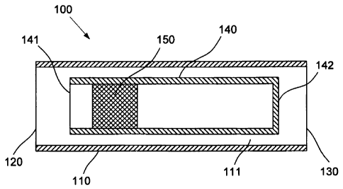
A first example of a water hammer arrester will now be described with
reference to Figure 1.
The water hammer arrester 100 is configured for installation in a water
pipeline and includes
an inlet 120 for receiving water from the water pipeline and an outlet 130 for
returning the
water to the water pipeline.
The water hammer arrester 100 also includes a body 110 which connects the
inlet 120 and the
outlet 130. Accordingly, the water hammer arrester 100 can be installed into
the water
pipeline by connecting the inlet 120 to an end of a first pipe in the water
pipeline and
connecting the outlet 130 to an end of a second pipe in the water pipeline,
such that water is
allowed to flow through the body 110 of the water hammer arrester 100 between
the inlet 120
and the outlet 130.
It will be appreciated that the direction of water flow through the body 110
may vary
depending on the particular installation of the water hammer arrester 100 in
the water
pipeline, and therefore the use of the terms inlet 120 and outlet 130 are used
for convenience
only and are not intended to restrict the direction of water flow to and from
the water
pipeline.
A piston assembly 140 is positioned in the body 110 in such a way that water
is allowed to
flow from the inlet 120 to the outlet 130 between the piston assembly 140 and
the body 110.
Accordingly, the flow of water through the body 110 in use is not
significantly obstructed by
the presence of the piston assembly 140 in the body 110.
CA 02860401 2014-06-25
WO 2012/097414
PCT/AU2012/000044
- 9 -
The piston assembly 140 is adapted to absorb pressure variations in the water
pipeline to
thereby at least partially reduce water hammer in the water pipeline in use.
In general, this is
achieved by using piston 150 that moves within the piston assembly 140 to
absorb at least
some of the pressure variations in the water flow. This helps to mitigate
hydraulic shock and
avoid problems associated with vibration, which in turn leads to noisy and
banging pipes.
In this example, the piston assembly 140 includes an open end 141 and a closed
end 142. The
piston 150 is exposed to water flowing through the water pipeline via the open
end 141, and a
resilient medium, such as a compressible gas or,-,a spring, is provided inside
the piston
assembly 140, between the piston 150 and the closed end 142. In use, the
resilient medium at
least partially opposes movement of the piston 150 towards the closed end 142,
so that
movement of the piston 150 within the piston assembly 140 is thereby at least
partially based
on a combined effect of the pressure of the water at the open end 141 and a
reaction provided
by the resilient medium within the piston assembly 140. As a result, the
resilient medium
applies a restoring force to the piston 150 so that the piston is urged
towards the open end 141
under normal water pressure and flow conditions, such as when a valve in the
water pipeline
is open and water is allowed to flow without substantial pressure variations.
Illustrative
examples of particular piston assembly 140 configurations, including examples
of the types
of resilient media that may be provided in the piston assembly 140, will be
discussed in more
detail below.
In one example, at least a portion of the body 110 is in the shape of an
elongate hollow
cylinder, and the inlet 120 and the outlet 130 are positioned at opposite ends
of the body 110.
Accordingly, the body 110 may be a section of pipe, and the inlet 120 and the
outlet 130 can
be ends of the section of pipe which may be connected to respective ends of
the first and
second pipes of the water pipeline using suitable pipe fittings. It will be
appreciated that a
standard pipe geometry may be used in this example.
In another example, the body 110 is a customised component that is configured
to retain the
piston assembly 140 between the inlet 120 and outlet 130, and thus may be
provided together
with the piston assembly 140 for installation into the water pipeline as a
complete assembly.
In this case, the body 110 may be mass produced using molded plastic, or any
other suitable
CA 02860401 2014-06-25
WO 2012/097414
PCT/AU2012/000044
- 10 -
material, in order to provide integral molded features for retention of the
piston assembly 140
and/or integral installation features such as threads in the inlet 120 and
outlet 130.
It will be appreciated that the body 110 can also be formed from metal,
whereby numerous
manufacturing methods will be available including machining, casting or
forming from metal
tubing or sheet metal. Other suitable materials include ceramics, which may be
cast into
desired geometries.
In view of the above, it will be appreciated that the water hammer arrester
100 can either be
provided as a single unit including the body 110 and the piston assembly 140,
or otherwise
the piston assembly 140 can be provided as an insert so that a functional
water hammer
arrester 100 can be constructed by inserting the piston assembly 140 into any
suitable body
110, such as a section of pipe. Accordingly, the piston assembly 140 may be
shaped to aid
insertion of the piston assembly 140 into the body 110.
In any event, a water hammer arrester 100 configuration in which the inlet 120
and the outlet
130 are positioned at opposite ends of the body 110 allows the water hammer
arrester 100 to
be installed in the water pipeline in an in-line arrangement, in which the
bulk flow of the
water through the water hammer arrester 100 is able to pass through the water
hammer
arrester 100 without undergoing a resultant change in direction between the
inlet 120 and the
outlet 130.
It will be appreciated that such an in-line installation arrangement allows
the water hammer
arrester 100 to be provided in the water pipeline with reduced space
requirements, compared
to conventional water hammer arresters, which typically include a piston
chamber that
protrudes perpendicularly from the water pipeline. It will be understood that
conventional
water hammer arresters of the protruding piston chamber type require a
substantial amount of
otherwise unoccupied space around the water pipeline in order to accommodate
the
protruding piston chamber, which will not be required when installing the
water hammer
arrester 100 in the in-line arrangement described above.
A further benefit of the in-line arrangement compared to conventional
protruding piston
chamber water hammer arresters is that the direction of movement of the piston
150 can be
CA 02860401 2014-06-25
WO 2012/097414
PCT/AU2012/000044
- 11 -
aligned with the direction of water flow through the water hammer arrester
100, to thereby
allow the piston 150 to be more directly exposed to the kinetic energy of the
flowing body of
water, along with any pressure waves propagating along the water pipeline. It
will be
appreciated that this acts to further improve the water hammer reduction
performance of the
water arrester 100 over conventional products.
In order to further illustrate the use of the water hammer arrester 100, a non-
limiting example
of an installation of a water hammer arrester 100 into a water pipeline will
now be described
with reference to Figure 2.
In this example, the water hammer arrester 100 is installed in the water
pipeline between two
to separate pipe sections 210, 220. Water is supplied to a flick mixer tap
200, through the pipe
sections 210, 220, and the water hammer arrester 100 which is connected
between the pipe
sections 210, 220 by the inlet 120 and outlet 130. The flow of water through
the tap 200 is
controlled by the operation of a tap handle 201 in the usual manner.
In the event that the tap handle 201 is used to rapidly close the tap 100 and
thereby suddenly
stop the flow of water through the tap 200, a pressure wave may be induced by
the rapid
momentum change in the water, which propagates through the water pipeline from
the closed
tap 200. As the pressure wave propagates through the water hammer arrester
100, the piston
assembly 140 positioned in the water flow path absorbs at least some of the
pressure
variations caused by the pressure wave and/or kinetic energy of the moving
water front. It
will be appreciated that absorption of pressure variations will help to reduce
the effects of
water hammer throughout the water pipeline, particularly in the vicinity of
the water hammer
arrester 100, thereby reducing the likelihood of associated damage, pipe
vibration and hence
noise.
It should be noted that Figure 2 merely illustrates one possible example of
use of the water
hammer arrester 100, and it will be appreciated that the water hammer arrester
100 may be
used in a wide range of situations in which the effects of water hammer may be
undesirable.
For example, the water hammer arrester 100 may be installed anywhere in a
water pipeline
which may be subject to pressure variations. Common examples in which an
installation of a
CA 02860401 2014-06-25
WO 2012/097414
PCT/AU2012/000044
- 12 -
water hammer 100 may be beneficial include water pipelines in the vicinity of
rapidly closing
valves, such as those found in washing machines or dishwashers.
It is often desirable to install the water hammer arrester 100 in a position
that is as close as
possible to the source of pressure waves, and it will be appreciated that the
reduced space
requirements of the water hammer arrester 100, particularly in view of the
ability to install
the water hammer arrester 100 in an in-line arrangement as illustrated in
Figure 2, help to
facilitate such an installation strategy. In contrast, conventional water
hammer arresters
usually require an elbow junction or the like and/or increased space to
accommodate a
protruding piston chamber in order to allow installation, and this acts to
limit the locations in
to which conventional water hammer arresters can be conveniently installed.
Given this, it will
be understood that the water hammer arrester 100 allows an improvement in
flexibility of
installation as compared to conventional water hammer arresters.
Despite the above discussed benefits of the in-line arrangement, it should be
appreciated that
other embodiments of the water hammer arrester 100 may also be provided,
whilst
maintaining a similar principle of operation. For example, the outlet 130 may
be configured
to return the water to the water pipeline at a different direction to the
direction the water is
received at the inlet 120, such that a change in the water flow direction is
effected as the
water flows through the body 110. It will be appreciated that one example of
such a
configuration would involve a body 110 with an integral elbow arrangement at
one end. In
that example, the piston assembly 140 would still be positioned in the body
110 in such a way
as to allow water to flow between the piston assembly 140 and the body 110,
such that the
water hammer arrester 100 would still offer improved water hammer reduction
performance
and reduced space requirements when compared to a conventional water hammer
arrester of
the protruding piston chamber type, irrespective of the change in water flow
direction.
A second example of a water hammer arrester will now be described with
reference to
Figures 3A to 30.
The cutaway views of Figures 3A and 3B allow the internal configuration of the
piston
assembly 140 within the body 110 to be better appreciated.
CA 02860401 2014-06-25
WO 2012/097414
PCT/AU2012/000044
- 13 -
In this example, it is noted that the body 110 has the inlet 120 and outlet
130 positioned at
opposite ends of the body 110 to allow for an in-line installation, as
described above. Both of
the inlet 120 and the outlet 130 are configured for connection to first and
second pipe sections
of the water pipeline at each end of the piston assembly 100. In this case,
the inlet 120 is
-- adapted to have a connection fitting inserted into inlet 120 for connection
to the first pipe
section, whilst the outlet 130 is adapted for insertion into suitable
connection fitting for
connection to the second pipe section.
The piston assembly 140 includes an elongate housing 345 with an open end 141
and a closed
end 142. The piston 150 is positioned in the housing 345 and is slidably
moveable along at
-- least a portion of the housing 345.
In use, water is allowed to flow through the inlet 120, around the housing 345
between the
piston assembly 140 and the body 110 and to subsequently exit the body 110 via
the outlet
130. A first end 351 of the piston 150 is exposed to the water at the open end
141 of the
housing 345 such that the piston 150 is urged towards the closed end 142 at
least in part by
-- the pressure of the water that is passing through the water hammer arrester
100.
In this example, the resilient medium provided inside the piston assembly 140
between the
piston 150 and the closed end 142 is a pressurised gas. The pressurised gas
may be
pressurised air or any other gas which may be retained at pressure in the
piston assembly 140.
The pressure of the pressurised gas provides a restoring force that urges the
piston 150
-- towards the open end 141 and the pressure is typically selected to be equal
to or greater than
the normal water pressure when water is allowed to flow freely though the
water pipeline. In
the event of an increase in water pressure, as may be caused by a rapidly
closing valve for
example, the piston 150 moves against the restoring force provided by the gas
pressure.
Preferably, the gas provided as the medium inside the piston assembly 140 will
be selected to
-- minimise the risk of leakage of the gas past the piston 150, to thereby
reduce loss of pressure
in the gas throughout the life of the water hammer arrester 100.
CA 02860401 2014-06-25
WO 2012/097414
PCT/AU2012/000044
- 14 -
In this example, the piston assembly 140 is configured to allow it to be
inserted into the body
110 and retained within the body 110 for use. An example external
configuration of the
piston assembly may be better appreciated by reference to Figures 3C and 3D.
At least a portion of the piston assembly 140 has a substantially
circumferential outer surface.
This outer surface of the housing 345 has a diameter that is less then a
diameter of an inner
wall of the body 110. The difference between the respective outer and inner
diameters of the
housing 345 and the body 110 provides a water passageway between the body 110
and the
piston assembly 140, allowing the passage of water therebetween.
In this example, the piston assembly 140 is adapted to be positioned coaxially
inside the body
110 to thereby define an annual water passageway around the outer surface of
the housing
345. In one particular example, the body 110 and piston assembly 140 are
dimensioned to
define an annular water passageway with a cross sectional area that is equal
to or greater than
a cross sectional area of the water pipeline in the pipe sections from/to
which the water flows.
It will be appreciated that this allows water to flow from the water pipeline
and through the
water hammer arrester 100 without the water hammer arrester 100 substantially
restricting to
the cross sectional area through which water is allowed to flow. Accordingly,
the water
hammer arrester 100 configured in the fashion described above will not
substantially obstruct
the flow of water through the water pipeline.
It will be appreciated that in order to provide a water passageway around the
piston assembly
140 which does not substantially obstruct the flow of water, the diameter of
inner surface of
the body 110 should be greater than the inner diameter of the pipes sections
of the water
pipeline. Whilst this will result in a marginal increase in space requirements
at the point of
installation of the water hammer arrester 100, as can be seen for example in
Figure 2, it will
be noted that the resulting installation is nevertheless more compact than a
conventional
water hammer arrester of the protruding piston chamber type may allow.
The housing 345 of the piston assembly 140 includes a plurality of lugs 343,
344 for
positioning the piston assembly 140 in the body 110. In this example, at least
some of the
lugs 343 are positioned at the open end 141 of the piston assembly 140, and at
least some of
the lugs 344 are positioned at the opposite, closed end 142 of the piston
assembly 140.
CA 02860401 2014-06-25
WO 2012/097414
PCT/AU2012/000044
- 15 -
As can be seen in Figures 3C and 3D, the lugs 343 at the open end 141 have a
different
configuration to the lugs 344 at the closed end 142. In particular, the closed
end lugs 344 are
connected across the closed end 142, whilst the open end lugs 343 protrude
from the open
end 141 in an open arrangement, in order to not obstruct the opening at the
open end 141 of
the piston assembly 140.
In any event, each of the plurality of lugs protrudes outwardly from the outer
surface of the
housing 345 to thereby maintain a separation between the outer surface of the
housing 345
and the inner wall of the body 110 when the piston assembly 140 is positioned
inside the
body 110.
In the present example, the lugs 343, 344 are integral with the housing 345
and thus may be
formed as part of the manufacture of the housing 345, such as using a plastic
moulding
process. However, it will be appreciated that the lugs 343, 344 may
alternatively be provided
in separate components which may be fitted to the housing 345 during assembly
of the water
hammer arrester 100. For instance, the lugs 343, 344 may be provided in the
form of end cap
components, adapted to be installed at the respective ends 141, 142 of the
piston assembly
140. These end caps may be permanently fastened to the housing 345 using
adhesive or any
other suitable fastening means, or held in place using an interference fit or
close engagement
with other features of the water hammer arrester 100 upon assembly.
In one example, the plurality of lugs are arranged circumferentially around
the housing 345
and each of the lugs 343, 344 protrudes outwardly from the outer surface of
the housing 345
by substantially the same distance, in order to substantially centralise the
piston assembly 140
within the body 110. The number and sizing of the lugs 343, 344 in this
circumferential
arrangement are selected to provide adequate radial support of the piston
assembly 140 whilst
minimising the obstruction presented to the flow of water by the lugs 343,
344. It will be
appreciated that in this case the assembly is therefore positioned
substantially coaxially inside
the body 110 to thereby define an annular water passageway between at least
part of the inner
wall of the body 110 and at least part of the outer surface of the housing
345.
As mentioned above, the cross sectional area of the annular water passageway
is based on the
respective diameters of the outer surface of the housing 345 and the inner
wall of the body
CA 02860401 2014-06-25
WO 2012/097414
PCT/AU2012/000044
-16-
110, and therefore it will be appreciated that the offset of the lugs 343, 344
from the outer
surface of the housing 345 will be based on the differences in those diameters
in order to
allow the correct positioning of the piston assembly 140 within the body 110.
A cross section schematic of the example of the water hammer arrester 100 of
Figures 3A and
3B is illustrated in Figure 3E.
In this example, the inlet 120 and the outlet 130 include respective threaded
portions 321, 331
which provide a convenient means for securing the water hammer arrester 100
into the water
pipeline at each end of the body 110. In this case, the inlet 120 is
configured as a female
threaded fitting, whilst the outlet 130 is configured as a male threaded
fitting. However, it
to will be appreciated that any suitable means for connecting the water
hammer assembly 100
into the water pipeline may be provided, and providing threaded portions 321,
331 on the
inlet 120 and the outlet 130 is not essential.
An example of the positioning of the piston assembly 140 inside the body 110
will now be
described in detail, with reference again to Figure 3E. In this example, the
body 110 includes
one or more steps 311, 312 circumferentially about the inner wall of the body
110, the steps
311, 312 being for axially restraining the piston assembly 140 in the body
110. The steps 311,
312 are configured such that ends of the lugs 343, 344, which extend
longitudinally from the
housing 345, abut the steps 311, 312 to thereby reduce or prevent axial
movement of the
piston assembly 140 inside the body 110. However, it will be appreciated that
any other
means for axially restraining the piston assembly 140 may be provided.
For example, the lugs 343, 344 may be configured to protrude from the outer
surface of the
housing 345 by a distance that is greater than the gap defined between the
outer surface of the
housing 345 and the inner wall of the body 110. It will be appreciated that
insertion of the
piston assembly 140 into the body 110 would therefore require an interference
fit. In this
case, friction due to the interference between the lugs 343 and 344 and the
body 110 provides
a degree of restraint of the piston assembly 140 relative to the body 110. In
an alternative
example, the lugs 343, 344 may be bonded to the inner wall of the body 110 to
similarly
restrain the piston assembly 140. It will be appreciated that interference fit
or bonding will
also provide restraint in the radial direction, such that rotation of the
piston assembly 140
CA 02860401 2014-06-25
WO 2012/097414
PCT/AU2012/000044
- 17 -
inside the body 110 is reduced or prevented. Any combination of one or more
means of
restraining the piston assembly 140 may be provided.
In another example, the lugs 343, 344 are formed from a material that is
selected to facilitate
the insertion of the piston assembly 140 into the body 110. For example, the
lugs 343, 344
may be formed from a resilient material, such as rubber, so that the lugs 343,
344 are allowed
to deform during insertion of the piston assembly 140 into the body 110. Lugs
343, 344
formed in this manner can allow the piston assembly 140 to be easily inserted
into a body 110
fitted with circumferential steps 311, 312 at each end of the body 110 as
described above.
Once the piston assembly 140 is inserted into the body 110, the deformed
resilient material of
the lugs 343, 344 may also provide a restraining force in a similar manner to
the interference
fit means of restraint described above. Accordingly, it will be appreciated
that rubber lugs
343, 344 may allow convenient insertion of the piston assembly 140 into a
section of pipe
without requiring any restraining features to be provided in the pipe for it
to serve as the body
110 of the water hammer arrester 100.
It will be appreciated that the above example methods of restraint may allow
the piston
assembly 140 with lugs 343, 344 as described above to be positioned within a
body 110 that
is provided by a section of pipe without any internal restraint features, such
as circumferential
steps or the like. Accordingly, a length of standard pipe may be converted
into a water
hammer arrester 100 by inserting and retaining a piston assembly 140 within
the pipe,
without requiring a customised component to serve as the body 110.
The path of the water flow between the piston assembly 140 and the body 110
can be seen as
indicated by the broken line and arrows along the length of the water hammer
arrester 100 as
shown in Figure 3E. It will also be appreciated that kinetic energy from the
flowing body of
water and any pressure waves passing through the water hammer arrester 100
will act upon
the piston 150 to move the piston 150 in a direction from the open end 141 of
the piston
assembly 140 towards the closed end 142.
As mentioned above, the piston assembly 140 of this example includes a
compressed gas
inside a chamber 390 defined by the housing 345 and the piston 150. The
compressed air
=
CA 02860401 2014-06-25
WO 2012/097414
PCT/AU2012/000044
- 18 -
provides a reaction opposing the motion of the piston 150 when it is moved by
an increase in
water pressure in the water pipeline. The compressed gas also acts to bias the
piston 150
towards the open end 141 in the absence of pressure variations in the water,
such that under
normal conditions the piston is at rest in a position at the open end 141.
In this example, a retaining ring 360 is also fitted to the open end 141 to
retain the piston 150
inside the piston assembly 140. The retaining ring 360 prevents the compressed
gas in the
chamber 390 from forcing the piston 150 out of the open end 141. Seals 370,
such as 0-rings
or the like, are also provided about the circumference of the piston 150 to
substantially
prevent leakage of either water into the chamber 390, or compressed gas from
the chamber
390.
Features of the piston assembly 140 will now be described in further detail
with reference to
Figures 3F to 30. A first end of the piston 351, which is exposed to the water
at the open end
141 of the housing 345, abuts the retaining ring 360 when the piston 150 is
biased towards
the open end 141 by the pressurised gas in the chamber 390. The retaining ring
360 is
positioned about an internal perimeter of the opening defined at the open end
141, and has an
internal diameter that is smaller than an external diameter of the piston 150,
such that the
piston 150 is prevented from exiting the opening. The retaining ring 360 is
fixed to the
opening upon assembly of the piston assembly 140. This may be achieved by
bonding the
retaining ring to the housing 345, by using an adhesive, welding or any other
means of
attachment.
A second end 352 of the piston 150 is exposed to the pressurised gas inside
the chamber 390.
The chamber 390 is defined within the housing 345 with the closed end 142 and
the second
end 352 of the piston 150 defining the longitudinal extremities of the chamber
390, such that
a volume of the chamber 390 changes as the piston 150 is moved along the
length of the
piston assembly 140. It will therefore be appreciated that as the piston 150
is moved from the
open end 141 towards the closed end 142, for example in response to an
increase in water
pressure in the water pipeline, the volume of the chamber 390 reduces, which
subsequently
results in a corresponding increase in pressure of the pressurised gas inside
the chamber 390.
This results in the pressurised gas providing an opposing reaction against the
movement of
CA 02860401 2014-06-25
WO 2012/097414
PCT/AU2012/000044
- 19 -
the piston 150 caused by the increased water pressure. As water pressure
decreases, the piston
150 returns to the open end 141, and it will be understood that this behaviour
will help to
maintain a substantially constant pressure in the water pipeline.
In this example, where the medium is pressurised gas, the second end 352 of
the piston 150
and the closed end 142 of the housing 345 each have relatively flat surfaces.
This helps to
allow a maximum range of movement of the piston 150 within the chamber towards
the
closed end 142, in the event that a variation in water pressure causes the
pressurised gas to be
highly compressed.
Figures 3H to 3J show further details of the housing 345 of the piston
assembly 140. The
front and rear views as shown in Figures 3H and 31 respectively illustrate the
protrusion of
the lugs 343, 344 outwardly from an outer surface 346 of the housing 345. In
this example, a
first array of four lugs 343 is provided at the open end 141 and a second
array of four lugs
344 is provided at the closed end 142.
The protrusion of the lugs 343, 344 from the ends of the housing 345 in the
longitudinal
direction helps to ensure that the flow of water from the pipelines to the
fluid pathway around
the housing 345 undergoes a gradual transition to thereby help to reduce
restrictions in the
flow of water. The outer extremities of the lugs 343, 344 define an effective
diameter that
may be equal to or greater that then internal diameter of the inner wall of
the body, depending
on whether an interference fit of the piston assembly 140 inside the body 110
is required.
An internal chamfer 349 is provided at the open end 141 to create a lead-in
for the piston and
seals and allow convenient positioning of the retaining ring 360.
An example of a piston 150 configured for use with the example water hammer
arrester 100
discussed above will now be described with reference to Figures 3K to 30.
In this example, the piston 150 includes at least one groove 353 defined from
an outer surface
354. Each groove 353 is adapted to retain a seal 370 around the circumference
of the piston
150, as can be seen in Figures 3F and 3G. In this example, two grooves 353 and
two
corresponding seals 370 are provided, such that one seal 370 positioned
towards the open end
121 of the piston assembly 140 will serve to substantially prevent water from
leaking into the
CA 02860401 2014-06-25
WO 2012/097414
PCT/AU2012/000044
- 20 -
chamber 390, whilst another seal 370 positioned towards the closed end 131 of
the piston
assembly 140 is for substantially preventing pressurised gas from leaking out
of the chamber
390 during movement of the piston 150.
In this example, the piston 150 is constructed with a hollow internal cavity
355 which is open
at the first end 351 of the piston 150. This hollow internal cavity 355 may be
provided for
manufacturing reasons since it allows a reduction in the material used to make
the piston and
has the added benefit of reducing the weight of the piston 150. However, it
will be
appreciated that the hollow internal cavity 355 and a piston 150 with a solid
construction can
be used.
Although the piston 150 may be manufactured from any suitable material
including metal or
ceramic materials, one particular embodiment includes a piston 150
manufactured from a
plastic material, using a molding process. Construction of the piston 150 from
molded plastic
allows greatly reduced manufacturing costs compared to the other materials and
manufacturing techniques.
Furthermore, the manufacture of the piston 150 from plastic allows the piston
150 and the
retaining ring 360 to both be molded as a single part during manufacture. This
is the case in
the example piston 150 of Figures 3K to 30, where the retaining ring 360 is
connected to the
piston 150 by a plurality of frangible tabs 364. The details of this
connection can be seen
more clearly in the detailed view of Figure 30. The tabs 364 are configured to
allow the
retaining ring 360 and the piston 150 to separate from one another upon
initial use of the
water hammer arrester 100, by having the tabs 364 break away from the piston
150 when the
piston 150 is moved away from the retaining ring 360 by a pressure wave in the
water flow,
or the like.
The manufacture of the piston 150 and retaining ring 360 as a single molded
part helps to
simplify handling and assembly of the water hammer arrester 100. The retaining
ring 360 is
bonded to the housing 345 in order to secure the retaining ring 360 in place
and thus prevent
the piston 150 from being expelled from the piston assembly 140 due to the
pressurised gas in
the chamber 390.
CA 02860401 2014-06-25
WO 2012/097414
PCT/AU2012/000044
- 21 -
In one example, the piston 150 also includes a wiper edge 356 around an
outside edge of the
first end 351 of the piston 150. The wiper edge 356 helps to prevent
contaminants from
entering the chamber 390 along the inner surface of the housing 345 during
movement of the
piston 150. Whilst the combined effect of the wiper edge 356 along with two
seals 370
positioned in grooves 353 of the piston 150 as described above provides
particularly effective
resistance to leakage and a barrier to contaminants, it will be appreciated
that any
combination of seals, wiper edges, or any other means of preventing leakage or
ingress of
contaminants can be provided.
A third example of a water hammer arrester will now be described with
reference to Figures
0 4A to 4M. It should be noted that this example embodiment includes a
number of similarities
to the second example described with reference to Figures 3A to 30, and
similar features will
be referenced using similar reference numbers throughout the following
description.
A primary difference in the configuration of this example of the water hammer
arrester 100
lies in the type of medium provided in the piston assembly 140. In particular,
in this example
the piston assembly 140 includes a spring 480 positioned inside the chamber
390 between the
piston 150 and the closed end 142 of the housing 345.
The spring 480 provides a similar functionality to the pressurised gas in the
previous example
water hammer arrester embodiment described with reference to Figures 3A to 30,
by
providing a restoring force against movement of the piston 150 under the
influence of
increased water pressure in the water pipeline. Accordingly, as the piston 150
moves away
from the open end 141 of the piston assembly 140, the spring 480 is
compressed. As a result
of this compression the spring 480 applies an increased reaction force on the
second end 352
of the piston 150 as it moves further away from the open end 141 of the piston
assembly 140.
Figure 4C illustrates a cross-sectional schematic of the example of the water
hammer arrester
100 of Figures 4A and 4B in order to more clearly show the configuration of
the spring 480
within the piston assembly 140.
It will be appreciated that the external configuration of the piston assembly
140 is generally
the same as that of the previously described water hammer arrester example,
whereby lugs
CA 02860401 2014-06-25
WO 2012/097414
PCT/AU2012/000044
- 22 -
343, 344 are provided at the ends of the housing 345 and the water is allowed
to flow around
the piston assembly 140 between an outer surface of the housing 345 and an
inner wall of the
body 110 for an annular passage way 111. However, the internal configuration
of the piston
assembly 140 includes particular adaptations to accommodate the spring 480 as
the reaction
medium inside the chamber 390. In particular, the housing 345 of the piston
assembly 140
includes a stop 481 extending inside the chamber from the closed end 142.
The stop 481 helps to prevent over-compression of the spring 480 when the
piston 150 is
moved towards the closed end 142 of the housing 345. It will be appreciated
that a length of
the stop 481 should therefore be selected to be greater than a length of the
spring 480 under
its maximum desirable compression, such that the piston 150 comes into contact
with the
internal face 482 of the stop 481 before the spring 480 is compressed beyond
desirable limits.
Further internal details of the piston assembly 140 in this example can be
seen with reference
to Figures 4D and 4E. In this case, the piston stop 481 is provided in the
form of an extruded
cross-shaped member in order to provide the stopping functionality with
efficient use of
material. The stop 481 also provides an additional function of resisting
spring buckling as the
spring 480 compresses with movement of the piston 150. It will be appreciated
that the
particular shape of the stop 481 helps to reduce deformation of the spring 480
in a non-axial
direction, particularly when the spring is in a highly compressed state as the
piston 150
approaches the closed end 142 of the housing 345.
Figures 4F to 4H provide further detail of the configuration of the housing
345 including the
piston stop 481, although it will be appreciated that, apart from the stop 481
the housing 345
is substantially the same as the piston housing 345 shown earlier with
reference to Figures 3H
to 3J. In any event, the cross-section of the stop 481 can be more clearly
seen in Figure 4F.
The piston 150 may also include particular adaptations for use with the spring
480, and these
can be seen with reference to 41 to 4M. A primary difference in this case is
that the piston 150
includes a recess 457 around an outer portion of the second end 352, wherein
the recess 457
is adapted to interface with an end of the spring 480. This recess 457 helps
to provide further
resistance to spring buckling, by substantially preventing slippage of the
spring 480 across
the second end 352 of the piston 150. Otherwise, it will be appreciated that
the piston 150 of
CA 02860401 2014-06-25
WO 2012/097414
PCT/AU2012/000044
- 23 -
this example includes generally similar features as per the example piston 150
described
above with reference to Figures 3K to 30.
A fourth example of a water hammer arrester 100 includes an alternative form
of piston
assembly 140 as illustrated in Figures 5A and 5B, which will now be described.
This form of
the piston assembly 140 is substantially similar to that illustrated in
Figures 3F and 30, in
which the piston assembly 140 includes a chamber 390 filled with a pressurised
gas acting as
the resilient medium. Similar features will be referenced using similar
reference numbers
throughout the following description.
The primary difference in the piston assembly 140 of Figures 5A and 5B,
compared to that of
Figures 3F and 30, resides in the particular inclusion of an additional 0-ring
571 positioned
between the retaining ring 360 and the piston 150. The 0-ring 371 acts as a
buffer or cushion
to reduce impact loads between the retaining ring 360 and the piston 150 in
use, caused by
the restoring force provided on the piston 150 by the pressurised gas within
the chamber 390.
This in turn can help to prevent damage to the retaining ring 360 and piston
150 and may
allow plastic materials with low impact strength to be used to form those
components.
Such an arrangement may also be used in versions of the piston assembly 140
including
different resilient media, such as the embodiment including a spring 480
positioned inside the
chamber 390 as shown in Figures 4D and 4E. The 0-ring 371 can thus reduce
impacts caused
by the restoring force provided on the piston 150 by the spring 480, in cases
where the spring
is in a normally compressed state when the piston assembly 140 is assembled.
However, it will be appreciated that spring loaded versions of the piston
assembly 140 may
be assembled such that the spring 480 is not normally compressively loaded, in
which case
impacts caused by the restoring force may already be reduced, such that an 0-
ring 371 may
not be warranted. Similarly, in pressurised gas versions of the piston
assembly 140, the
degree of pressurising can be adjusted to reduce the impacts between the
piston 150 and the
retaining ring 360 in use, such that an 0-ring 371 may not be necessary.
Nevertheless, the 0-ring 371 allows the use of resilient media which provide
relatively higher
restoring forces which can improve the water hammer arrester performance
and/or the use of
CA 02860401 2014-06-25
WO 2012/097414
PCT/AU2012/000044
- 24 -
components formed with materials having lower impact resistance which may
allow cheaper
manufacture.
Further details of the piston 150 and the retaining ring 360 used in the
example piston
assembly 140 of Figures 5A and 5B can be seen in Figures 5C to 5G. In this
case, the
retaining ring 360 includes an open groove 565 about its circumference to
allow the 0-ring
371 to be fitted in a suitable position between the piston 150 and the
retaining ring 360. Other
details are substantially similar to those already described with reference to
Figures 3K to 30.
A fifth example of a water hammer arrester 100 can be provided with a further
alternative
form of spring loaded piston assembly 140 as illustrated in Figures 6A to 6C.
The piston
assembly 140 of this example has similar operation to that described with
reference to
Figures 4D and 4E, but with a different configuration of spring 480, piston
150 and housing
345 which allows the piston assembly to have a reduced overall length whilst
having a
comparable range of piston motion.
In this example, the piston 150 includes a relatively large central recess
657, formed in the
S second end 352 of the piston, within which an end of the spring 480 can
be located. The other
end of the spring 480 is located in a shallow central recess 685 at the closed
end 142 of the
piston assembly 140.
The piston assembly 140 in Figure 6A also includes a plurality of longitudinal
ribs 683
projecting inwardly from the inner surface of the housing 345, rather than a
central stop 481
(as per the piston assembly 140 of Figures 4D and 4E).
When the piston 150 moves towards the closed end 142 of the piston assembly
140 in use, an
outer annular surface of the second end 352 of the piston 150 (surrounding the
central recess
657) comes into contact with end surfaces 684 of the longitudinal ribs 683
before the spring
480 is compressed beyond desirable limits. It will be appreciated that this
will provide a
similar stopping functionality as provided by the central stop 481 shown in
Figures 4D and
4E, to thereby prevent over compression of the spring.
However, the particular arrangement in this example allows the spring 480 to
be located such
that it extends inside the volume of the piston 150, thus allowing the overall
length of the
CA 02860401 2014-06-25
WO 2012/097414
PCT/AU2012/000044
- 25 -
piston assembly 140 to be reduced. It will also be appreciated that this
arrangement also
allows for easier manufacture of moulded components.
As can be seen in Figures 6B and 6C, which show further details of the piston
assembly 140
of Figure 6A, the central recess 657 in the second end 352 of the piston means
that the piston
150 can have a flat surface at the first end 351 and yet still have an
effectively hollowed
construction to provide similar manufacturing advantages as for the piston 150
discussed with
reference to Figures 3K to 30.
In this example, the retaining ring 360 is also fitted with an 0-ring 571 as
described above for
Figures 5A to 5G.
Other than the features described above, the piston assembly 140 is generally
of a similar
design as described for earlier examples, and similar reference numerals have
been used to
indicate similar features.
A sixth broad example of a water hammer arrester 100 will now be described
with reference
to Figure 7. As can be seen, this example is similar to the broad form of the
water hammer
arrester 100 described with reference to Figure 1, and similar reference
numerals have thus
been used to indicate similar features. This example further includes optional
features which
may be suitably provided in versions of the water hammer arrester 100 having a
thin walled
metallic construction.
The piston assembly 140 includes an inwardly projecting retaining feature 766
positioned at
the open end 141, for retaining the piston 150 within the piston assembly 140.
The retaining
feature 766 is suitably provided by inwardly deforming the piston assembly 140
housing near
the open end 141. It will be appreciated that a thin walled metallic housing
can be cold
worked through roll grooving, crimping, dimpling or any suitable process to
provide this
retaining feature 766 in a cost effective manner.
Figure 7 also illustrates the option of providing a reduction in cross
sectional area from the
body 110 to the water pipeline connection points at the inlet 120 and the
outlet 130. This
reduction can be selected to ensure that the cross sectional areas of the
inlet 120 and the
outlet 130 are substantially similar to the cross sectional area of the
passageway between the
CA 02860401 2014-06-25
WO 2012/097414
PCT/AU2012/000044
- 26 -
piston assembly 140 and the body 110 through which the water flows in use.
When the body
110 is formed from a metal tube or the like, the body 110 can be formed to
include this
reduction in cross sectional area using a single component. Alternatively,
separate adapter
components can be provided to achieve an effective reduction in cross
sectional area.
It will be appreciated that, whilst the features shown in Figure 7 are
particularly well suited to
thin walled metallic construction, these may also be provided in water hammer
arresters
formed from plastic or any other suitable materials.
A seventh example of a water arrester 100, particularly having a thin walled
metallic
construction, will now be described with reference to Figures 8A to 8C. The
water arrester
to 100 of this example may be suitably manufactured from copper tubing or
otherwise formed
from any other suitable metal tubing or metal structure formed from metal
sheet, and it will
be appreciated that this example illustrates further desirable implementation
features further
to the broad example of Figure 7.
In this example, the body 110 is formed from a length of copper tubing in
which the inlet 120
and the outlet 130 at the ends have reduced cross section diameters compared
to the cross
section throughout the central portion of the body 110. The inlet 120 and
outlet 130 may be
formed using known tube end forming techniques to provide reduced ends 821,
831,
following placement of the piston assembly 140 within the body 110. It will be
appreciated
that the reduced ends 821, 831 can be formed using any other suitable
fabrication techniques.
The body 110 further includes a plurality of inwardly protruding dimples 811,
812, which are
provided for positioning the piston assembly 140 inside the body 110. As can
be more readily
appreciated with reference to Figures 8B and 8C, there are two depths of
dimples 811, 812.
Shallow dimples 811 having a first, relatively shallow depth are provided for
locating the
piston assembly 140 radially and are thus provided in longitudinal positions
registering with
the housing 345 of the piston assembly 140 and protrude inwardly sufficiently
to engage the
housing 345. Other, deeper dimples 812 having a relatively greater depth are
provided to
restrain the piston assembly 140 axially, and accordingly these dimples 812
are provided to
register with the ends 141, 142 of the piston assembly and protrude beyond the
housing 345.
CA 02860401 2014-06-25
WO 2012/097414
PCT/AU2012/000044
- 27 -
A plurality of dimples 811, 812 of each depth are distributed radially as can
be seen in Figure
8B. In this example, three dimples 811, 812 are arranged radially at four
longitudinal
positions along the body 110, to provide suitable location and retention of
the piston
assembly 140, although it will be appreciated that different dimple
arrangements may be
used. In alternative examples, other inwardly protruding features such as
radius grooves or
the like may be provided instead of dimples to provide similar locating and
retaining
functionality.
In this example, the piston assembly 140 is of the pressurised gas type, in
which the housing
345 defining the chamber 390 is also formed using copper tubing.
The open end 141 of the piston assembly 140 is rounded inwardly in this case
to form a
retaining lip 867. The retaining lip 867 provides a means of retaining the
piston 150 within
the piston assembly 140 without requiring a separate retaining feature such as
the retaining
ring 360 used in previously described examples.
The closed end 142 of the piston assembly 140 can be formed using any known
techniques
for closing an end of a copper tube, including cold end closing techniques and
brazing/soldering/welding of a cap onto the end of the tube.
In this case, the piston 150 has a symmetrical construction which is
simplified compared to
earlier examples, since the inward rounding of the open end 141 to form the
retaining lip 867
removes the need for providing separate piston retaining features (which have
been formed=
integrally with the piston 150 in previous examples). Nevertheless, the piston
150 may be
formed in a similar fashion to those previously described, for example as a
moulded plastic
component.
It will be appreciated that the end forming processes to provide the reduced
ends of the body
110 and the housing 345 may be performed at appropriate stages of the assembly
of the
components of the water hammer arrester. For example, the open end 141 of the
piston
assembly can be formed by rounding the housing 345 after the piston 150 is
installed into the
chamber 390 along with gas at a desired pressure, and at least one of the
reduced ends 821,
CA 02860401 2014-06-25
WO 2012/097414
PCT/AU2012/000044
- 28 -
822 can be formed after installation of the completed piston assembly 140 into
the body 110
to complete the assembly.
The particular configuration of the water hammer arrester illustrated in
Figures 8A to 8C
even further reduces the number of components, whilst remaining relatively
easy to
manufacture and assemble.
In a further optional variation of the above example, the dimples 811, 812 may
be omitted,
and the piston assembly 140 may be positioned within the body 110 using lugs
343, 344
similar to those described above in previous examples. The lugs 343, 344 may
be
conveniently provided as end caps installed at the respective ends 141, 142 of
the piston
assembly 140, as discussed above with reference to Figures 3C and 3D. In this
case, the lugs
343 may be suitably configured to engage the reduced ends 821, 831 to
longitudinally
restrain the piston assembly 140.
In view of the above examples, it will be appreciated that the water hammer
arrester 100
described herein provides a means of reducing water hammer in a water pipeline
with
reduced space requirements and improved performance when compared to
conventional
water hammer arresters, due to the capability to install the water hammer
arrester 100 in an
in-line arrangement.
Furthermore, by utilising relatively inexpensive plastic manufacturing
methods, and reducing
the complexity and number of parts, a functional water hammer arrester 100 can
be provided
at a reduced cost compared to conventional water hammer arrester devices. The
piston
assembly 140 is also capable of being provided with suitable dimensions to fit
inside a
standard pipe section, to allow the water hammer arrester functionality to be
provided without
requiring a customised body 110 component. It will be appreciated that this
allows improved
flexibility in the scenarios in which the water hammer arrester can be
installed.
In contrast with conventional in-line water hammer arrester arrangements, the
piston 150 of
the water hammer arrester 100 is positioned directly in the water flow path,
and therefore
kinetic energy from the flowing body of water and pressure waves are allowed
to directly
CA 02860401 2015-10-28
06 hilleA10200-102,1911(1266AUI1Specificatiun and AmendinentOpmficanon
liled.DOC-23/10/2013
- 29 -
impinge upon the piston 150. It will be appreciated that this arrangement
results in improved
attenuation of water hammer in the water pipeline.
It should be understood that the use of the term "medium" throughout the above
description is
not intended to particularly restrict the contents of the chamber 390 of the
piston assembly
140 or the manner in which the restoring force is provided to the piston 150.
Accordingly, it
will be appreciated that the term "medium" includes a compressed gas, such as
compressed
air, or any other resilient member, such as a spring, as exemplified in the
above described
embodiments.
It should also be understood that the generally cylindrical shapes of the body
110 and housing
345 of the piston assembly 140 of the above described embodiments are merely
examples of
the possible shapes which may be convenient for a water hammer arrester 100 in
accordance
with the present invention, and are not intended to be limiting. For example,
the housing 345
may have a square cross section. In one example, the corners of a suitably
dimensioned
square housing 345 may act as lugs 343, 344, to thereby allow the piston
assembly 140 to be
positioned and/or restrained inside a body 110, such as a cylindrical pipe.
Accordingly, it will
be appreciated that any combination of shapes can be used to provide the
functionalities
described above.