Note: Descriptions are shown in the official language in which they were submitted.
CA 02860573 2014-07-16
BRAKE SYSTEM WITH LINKING EFFECT
FIELD OF THE INVENTION
[0001] The present invention relates to a brake system for a bicycle, and
more
particularly to a brake system with linking effect which brakes a bicycle's
rear
wheel before a front wheel.
BACKGROUND OF THE INVENTION
[0002] With the popularity of the sport of cycling, there are more and more
people riding bicycles for recreation. In a conventional bicycle brake system,
the
braking operation is driven by a rider who presses brake levers installed on
handles, and the front and rear wheels will be braked accordingly. The
conventional bicycle brake system performs the braking operation for each
individual brake of front wheel and rear wheel. In other words, when only one
of the levers is being pressed, it drives only the brake connected to that
lever. The
brake levers in related to a front wheel or a rear wheel are arbitrarily
installed on
left side handle and right side handle depending on every different
manufacturer,
so therefore when a rider with less physical reaction in choosing which wheel
should be braked may cause an emergency incident, because of his/her wrong
choosing of brake lever.
[0003] Accordingly, a rider pressing a wrong brake lever during a high
speed
riding may causes a flip over of a bicycle. Because if, in a high speed
riding, a
front wheel is suddenly braked prior to a rear wheel, the inertia force from
the rear
wheel will overwhelm the braking force in the front wheel to thus cause a flip
over.
[0004] In addition, since a gravity center of bicycle is allocated on a
frame
body, the balancing itself is complicated. An emergency situation will let it
even
more complicated, since a rider becomes difficult to make a prompt analysis in
such a rush moment to determine whether a front wheel, a rear wheel or both
wheels should be braked. Moreover, to remember which brake lever corresponds
to which wheel is another problem that a ride may not be able to react.
Moreover,
CA 02860573 2014-07-16
if a rider only brakes the rear wheel, it may cause the non-braked front wheel
driving the bicycle to run a unexpected distance, which may also cause an
accident.
SUMMARY OF THE INVENTION
[0005] The present invention is provided for solving the above drawbacks of
the conventional brake system of a bicycle. The drawbacks, which usually
happens in a high speed riding, includes:
1) The hazard results from only braking the front wheel. A gravity
center of bicycle becomes lower when the front wheel is braked, and a
thrusting
force from the moving rear wheel will lift a rear side of bicycle to cause the
bicycle to flip over.
2) The risk results from only braking the rear wheel. Although the
rear wheel has been braked and stopped, but the front wheel remains moving
forward in a high speed to thus keep the bicycle running for an unexpected
distance to cause a safety threat.
[0006] In spite that there are well-known technologies that employ a brake
system for braking the front wheel and the rear wheel synchronously, including
the employment of a pulley mechanism, an oil cylinder, a ratchet mechanism or
even a piston mechanism, there still have some disadvantages such as being too
large in size to become not suitable for installing on a bicycle frame, being
easy to
scratch the frame surface due to its back and forth sliding operation, or
being
complicated for installation because of a large amount of part elements.
[0007] Accordingly, the present invention is to provide a brake system with
linking effect that overcomes the aforementioned drawbacks of the conventional
bicycle brake system.
[0008] The present invention provides a safety brake system that brakes a
rear
wheel before a front wheel, so as to further enhance the riding safety of a
bicycle
rider.
[0009] The brake system with linking effect of the present invention
comprises a rear-wheel brake device and a front-wheel brake device.
[0010] According to an aspect of the present invention, the rear-wheel
brake
2
CA 02860573 2014-07-16
device includes a first rotating member, a first shifting member which is
allocated
in the first rotating member, and a first drawing member encircling the first
rotating member that is with a first radius, wherein the rear-wheel brake
device is
drawn by the first drawing member to launch a rotation to brake a rear wheel
from
a first initial position.
[0011] According to an aspect of the present invention, the front-wheel
brake
device including a second rotating member, a second shifting member which is
allocated in the second rotating member, and a second drawing member
encircling
the second rotating member that is with a second radius, wherein the front-
wheel
brake device is drawn by the first drawing member to launch a rotation to
brake a
front wheel from a second initial position.
[0012] According to an aspect of the present invention, the first shifting
member and the second shifting member are assembled by slide-fitting each
other
in a sliding buffer space between the first shifting member and the second
shifting
member, so as to allow the first shifting member to draw the front-wheel brake
device to perform braking operation.
[0013] According to an aspect of the present invention, the second radius
is
larger than first radius, so as to allow the second drawing member and the
first
drawing member brake the front wheel and the rear wheel in a substantially
synchronous manner.
[0014] According to an aspect of the present invention, the first rotating
member returns the first shifting member back to the first initial position,
and/or
the second rotating member returns the second shifting member back to the
second initial position.
[0015] According to an aspect of the present invention, the first rotating
member and the second rotating member are coaxial.
[0016] According to an aspect of the present invention, the first shifting
member is an engaging projecting element and the second shifting member is an
engaging groove element.
[0017] According to an aspect of the present invention, the first shifting
member is an engaging groove element and the second shifting member is an
engaging projecting element.
[0018] According to an aspect of the present invention, the rear-wheel
brake
3
CA 02860573 2014-07-16
device is for braking the rear wheel and the front-wheel brake device is for
braking the front wheel.
[0019] According to an aspect of the present invention, the first drawing
member and the second drawing member are brake cables.
[0020] According to an aspect of the present invention, a first rotating
element
of the first rotating member and a second rotating element of the second
rotating
member are coaxially and are respectively installed on inner portions of the
rotating member and the second rotating member.
[0021] According to an aspect of the present invention, the first shifting
member and the second shifting member are installed on outer portions of the
first
rotating member and the second rotating member.
[0022] According to an aspect of the present invention, the first drawing
member and the second drawing member draws outer sections of the rear-wheel
brake device and the front-wheel brake device.
[0023] With the characteristic features of the present invention as above,
a
braking operation is able to prevent the front wheel from being braked prior
to the
rear wheel. Since both front and rear brakes are controlled by the rear-wheel
brake device and the front-wheel brake device, a braking operation that brakes
the
rear wheel prior to the front wheel can be operated effectively. In the
present
invention, the rear wheel will be braked immediately, and the front wheel will
be
braked 0.1 to 0.2 seconds later so as to prevent from the danger of wrong
pulling
of the lever.
[0024] Moreover, the mechanism of braking the front and rear wheels
non-synchronously prevents a rider from being thrown away by the inertia
force.
The brake system of the present invention is applicable to any type of
bicycles,
and either the front or rear-wheel brake device can be used to control the
wheels
to thus effectively prevents a rider from mistakenly braking the front wheel
during
a high speed riding or in a unexpected dangerous situation.
BRIEF DESCRIPTION OF THE DRAWINGS
[0025] The technical means adopted by the present invention to achieve the
above and other objects can be best understood by referring to the following
4
CA 02860573 2014-07-16
detailed description of the preferred embodiments and the accompanied
drawings.
[0026] Fig. 1 is a front view illustrating the brake system with linking
effect
of the present invention.
[0027] Fig. 2 is another front view illustrating the brake system with
linking
effect of the present invention.
[0028] Fig. 3 is a top view illustrating the brake system with linking
effect of
the present invention.
[0029] Fig. 4 is a schematic diagram illustrating an example of applying
the
present invention on a bicycle.
DETAILED DESCRIPTION OF THE PREFERRED EMBODIMENTS
[0030] Hereinafter, a preferable embodiment of the present invention is
explained with reference to Figs 1 to 4, and the scope of the present
invention is
not limited to the following embodiment.
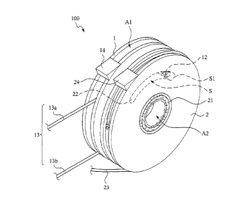
[0031] In an embodiment, the brake system with linking effect 100 of the
present invention is installed on a bicycle B. The brake system with linking
effect 100 includes a rear-wheel brake device 1 and a front-wheel brake device
2,
wherein the rear-wheel brake device includes a first rotating member 11, a
first
shifting member 12 which is allocated in the first rotating member 11, and a
first
drawing member 13 encircling the first rotating member 11 that is with a first
connecting radius r 1 as shown in Fig. 3. On the other hand, the front-wheel
brake device 2 includes a second rotating member 21, a second shifting member
22 which is allocated in the second rotating member 21, and a second drawing
member 23 encircling the second rotating member 21 that is with a second
connecting radius r2 as shown in Fig. 3., in which r2>r 1.
[0032] In this embodiment, the first drawing member 13 and the second
drawing member 23 of the present invention are brake cables as shown in Figs 1
and 2, wherein the first drawing member 13 includes an upper drawing member
13a and a lower drawing member 13b, which are separate to each other. One end
of the upper drawing member 13a of the first drawing member 13 is connected to
both of a right brake lever B1 and a left brake lever B3, and another end of
the
upper drawing member 13a is connected to the first rotating member 11 as show
CA 02860573 2014-07-16
in Fig 1. One end of the lower drawing member 13b is connected to the first
rotating member 11, and another end is connected to a rear-wheel brake B2. One
end of the second drawing member 23 is connected to the second rotating member
21, and another end is connected to a front-wheel brake B4. By means of above
configuration, the rear-wheel brake device 1 is for braking a rear wheel, and
the
front-wheel brake device 2 is for braking a front wheel. In this embodiment,
the
rear-wheel brake device 1 further includes a bumping member 14, and the
front-wheel brake device 2 further includes a bumping member 24, wherein the
function of bumping member 14 and 24 is to prevent the rear-wheel brake device
1 and front-wheel brake device 2 from over rotating when the front-wheel brake
and the rear-wheel brake are released. The first drawing member 13 and the
second drawing member 23 draw an outer sections W of the rear-wheel brake
device 1 and the front-wheel brake device 2.
[0033] As shown in the Fig. 3 and Fig. 4, the rear-wheel brake device 1 and
the
front-wheel brake device 2 both has an outer portion Al and an inner portion
A2.
A first rotating element 18 of the first rotating member 11 and a second
rotating
element 28 of the second rotating member 21 are coaxially installed on the
inner
portions A2 of the rear-wheel brake device 1 and the front-wheel brake device
2.
On the other hand, the first shifting member 12 and the second shifting member
22 are respectively installed on the outer portions A1 of the rear-wheel brake
device 1 and the front-wheel brake device 2. In this embodiment, the first
shifting member 12 is an engaging projecting element and the second shifting
member 22 is an engaging groove element, wherein the first shifting member 12
can be sliding and engaging with the second shifting member 22 as covered
within
the front-wheel brake device 2 as illustrated in Fig. 1 and 2 as the broken
line
portion. It can be understood that in another embodiment the first shifting
member can be an engaging groove element and a second shifting member can be
an engaging projecting element. Meanwhile, the first drawing member 13 and
the second drawing member 23 are provided to pull the outer portions A 1 of
the
rear-wheel brake device 1 and front-wheel brake device 2 to thus achieve a
connection to a right brake lever Bl, a rear-wheel brake B2, a left brake
lever B3,
and a front-wheel brake B4.
[0034] By means of the present invention, when a rider presses either the
right
6
CA 02860573 2014-07-16
brake lever B1 or the left brake lever B3, or presses both levers together, a
pulling
force that is transferred to the rear-wheel brake device 1 and the front-wheel
brake
device 2 through the first drawing member 13 and the second drawing member 23
will drive the first shifting member 12 and the second shifting member 22 that
are
slide-fitting with each other. The first shifting member 12 that is installed
on the
first rotating member 11 is initially slide with respect to the second
shifting
member 22 from a first initial position P1 of the rear-wheel brake device 1.
If
the pulling force continues, the first shifting member 12 will be slide to a
position
where it is a second initial position P2 of the front-wheel brake device 2,
during
which the first shifting member 12 is limited for the movement so that the
against
force will drive the second shifting member 22 to rotate the second rotating
member 21. Accordingly, the driven rotating second rotating member 21 will
drive the front-wheel brake B4 to brake.
[0035] In other words, when the right brake lever B1 and the left brake lever
B3
are not pressed, there are no pulling force applied to the rear-wheel brake
device 1
and the front-wheel brake device 2, so that the first shifting member 12 is at
a first
initial position P1 with respect to the second shifting member 22. When the
right
brake lever B1 or the left brake lever B3 is pressed, the upper drawing member
13a draws the rear-wheel brake device 1 from the first initial position P1 to
the
second initial position P2 if the pressing continues. Thereafter the upper
drawing
member 13a continues to draw the front-wheel brake device 2 to thus drag the
second drawing member 23. In the present invention, the first shifting member
12 and the second shifting member 22 are slide-fitting with each other and are
sharing a sliding space S (located inside a groove of the second shifting
member
22). The present invention will perform the braking operation in a manner that
the rear wheel is braked prior to the front wheel regardless of either the
right brake
lever B1 or the left brake lever B3 of the bicycle B is pressed.
[0036] In other words, by means of the sliding space S, the front-wheel brake
B4 is driven by the front-wheel brake device 2 for a braking to thus complete
the
entire braking operation of the bicycle B. Meanwhile, as illustrated in Fig.
3,
since the second radius r2 of the encircled second drawing member 23 with
respect to the rotation axis is larger than the first radius r 1 of the
encircled first
drawing member 13 with respect to the rotation axis, the pulling speed of the
7
CA 02860573 2015-09-28
second drawing member 23 will be faster than the first drawing member 13 so
that
the front-wheel brake device 2 drives the front-wheel brake B4 for performing
braking to the front wheel in a faster speed than that of the rear-wheel brake
device 1. Accordingly, the front wheel braking and the rear wheel braking can
be
more synchronous. By means of adjusting an appropriate proportion ratio of the
first radius rl to the second radius r2, the front wheel and the rear wheel
can be
braked more synchronously in the entire braking operation of bicycle B.
[0037] In addition, when a rider stops pressing the right brake lever B1
and/or
left brake lever B3, the first rotating member 11 will return the first
shifting
member back to the first initial position P1 with respect to the second
shifting
member 22.
[0038] By means of the above, the present invention prevents the situation
that
the front wheel is braked prior to the rear wheel. The present invention
enables
the rear-wheel brake device 1 and the front-wheel brake device 2 to control
the
front wheel braking and rear wheel braking. Moreover, the present invention
enables to brake the front wheel and the rear wheel with different speeds to
thus
brake the both wheels synchronously to thus avoid a situation that a rear
wheel is
fully braked but the front wheel is not fully braked. Moreover, by the
different
braking speeds of the front wheel and the rear wheel, different applying
forces can
be applied to the front wheel and the rear wheel so that the braking procedure
is
more steady and avoid the accidents.
[0039] Moreover, the brake system with linking effect 100 of the present
invention is able to be contained in a container 3 for being installed on a
frame of
the bicycle B, in which the installation position is not limited to the
position as
illustrated in Fig. 5.
8