Note: Descriptions are shown in the official language in which they were submitted.
CA 02860582 2016-02-05
1
OCCLUSION DEVICES AND METHODS OF THEIR MANUFACTURE AND USE
CROSS-REFERENCE TO RELATED APPLICATIONS
[0001] This application claims the benefit of priority of U.S. Provisional
Application
No. 61/586,633, filed January 13, 2012.
TECHNICAL FIELD
[0002] This disclosure relates generally to medical devices, and more
specifically
to devices for occlusion of a bodily lumen, cavity, vessel, or organ.
BACKGROUND
[0003] Many clinical situations require the reduction or complete stoppage
of fluid
flow (e.g., blood flow) in some region of a patient's body. Treatments for
aneurysms,
arteriovenous malformations, traumatic fistulae, and tumor embolization
provide a
few notable examples. These and other conditions often require that the fluid
flow
through at least a portion of a bodily lumen, cavity, vessel, or organ be
blocked.
[0004] Occluders, plugs, and embolic coils are examples of devices that can
be
implanted in a patient to block fluid flow in a lumen, cavity, or organ. In
some cases,
the implanted device alone sufficiently provides the desired blockage. In some
cases, the implanted device induces thrombosis, and the combination of the
device
and the thrombus provide the desired blockage. For example, vascular occlusion
devices may be deployed within a blood vessel at the site of an aneurysm, or
within
the aneurysm, of the brain or limbs. During deployment, the configuration of
the
device may change to an operational size and shape to reduce the flow of blood
through the weakened section of the blood vessel. Thrombus may form on the
occlusion device to further seal off blood flow in the area of the aneurysm,
thereby
preventing its ballooning or rupture. A typical intracranial procedure would
consist of
placing one or more coils into the aneurysm to fill the void, thus causing
thrombus to
form, and reducing the pressure within the aneurysm. Often this is done
through a
CA 02860582 2014-07-03
WO 2013/106694
PCT/US2013/021209
2
stent or "stentriever" to help prevent protrusion of the coil into the lumen
of the
vessel.
[0005] An embolic coil is a type of vascular occlusion device. Embolic
coils can be
constructed from a biocompatible metal wire, such as a shape memory metal
alloy.
Use of a shape memory material may allow the device to be arranged in a low-
profile
configuration for transcatheter deployment, and for the device to expand to an
operational size and shape when deployed at the target location within the
patient's
vasculature.
SUMMARY
[0006] This disclosure provides implantable medical devices for the
occlusion of a
bodily lumen, cavity, vessel, or organ. This disclosure also provides methods
for
manufacturing such occlusion devices, and methods for treating a subject using
the
occlusion devices.
[0007] Particular embodiments of the subject matter described in this
specification
can be implemented so as to realize one or more of the following advantages.
In
some embodiments, the implantable occlusion devices are functionally enhanced
by
the inclusion of membranous materials to increase the profile size and the
thrombogenicity of the occlusion devices. In some embodiments, the membranous
material on the occlusion devices is configured as multiple elongated fringe
members to enhance the profile size and the thrombogenicity of the occlusion
devices. In some embodiments, the occlusion devices are functionally enhanced
by
the inclusion of a membranous cup-shaped portion configured in an everted
arrangement that substantially blocks fluid flow from passing through the
occlusion
device.
[0008] Disclosed are devices for full or partial occlusion of a lumen,
cavity, vessel,
or organ in a bodily tissue. The devices provided herein can be used to treat,
for
example, aneurysms, arteriovenous malformations, traumatic fistulae,
endoleaks,
wounds, various cancers, and many other conditions. The disclosed devices
include, for example, occluders, coils, and plugs. In some embodiments, the
occlusion devices provided herein include at least one wire and a membranous
material. In some embodiments, the membranous material is disposed around the
CA 02860582 2014-07-03
WO 2013/106694
PCT/US2013/021209
3
wire (e.g., by wrapping) and may be incised along at least a portion of its
length to
form a fringe extending outwardly from and exterior to the wire. The incisions
effectively generate an external fringe having filaments or strips extending
along the
wire. In some embodiments, for example those including an elastomeric
membranous material, the occlusion devices provided herein are not incised to
form
fringes. In some embodiments, the occlusion devices provided herein include a
cup
formed of the membranous material. In some embodiments, the cup is adapted to
substantially block fluid flow through the device to aid in occluding or
limiting fluid
flow through the lumen.
[0009] In one general aspect, an implantable occlusion device comprises at
least
one wire having shape memory properties and a flexible polymer sheet; the
sheet is
disposed around the wire, and the sheet includes an external fringe along at
least a
portion of a length of the sheet.
[0010] In various implementations the external fringe may comprise an
incised
portion of the sheet; at least a portion of the fringe may be non-integral to
the sheet;
the fringe may extend substantially an entire length of the wire; the sheet
may be
attached to the wire at one or more locations on the wire; the sheet may
comprise
ePTFE; the implantable occlusion device may further comprise an
endothelization
promoting agent, anti-inflammatory agent, or a healing agent; and the
implantable
occlusion device may further comprise one or more radiopaque markers.
[0011] In a second general aspect, an implantable occlusion device comprises
at
least one wire having shape memory properties and a flexible polymer tube; the
tube
is disposed around the wire, and the tube includes an external fringe along at
least a
portion of a length of the tube.
[0012] In various implementations at least a portion of the wire may be
located inside
a lumen of the tube; the tube may comprise a polymer strip that is wrapped
around
at least a portion of the wire; the external fringe may comprise an incised
portion of
the tube; at least a portion of the fringe may be non-integral to the tube;
the fringe
may extend substantially an entire length of the wire; the fringe may have a
length
that extends beyond a length of the wire; the tube may be attached to the wire
at one
or more locations on the wire; the tube may comprise ePTFE; the implantable
CA 02860582 2014-07-03
WO 2013/106694
PCT/US2013/021209
4
occlusion device may further comprise an endothelization promoting agent, anti-
inflammatory agent, or a healing agent; and the implantable occlusion device
may
further comprise one or more radiopaque markers.
[0013] In a third general aspect, a method of making an implantable occlusion
device
comprises providing at least one shape memory wire and forming the shape
memory
wire into a coil, the coil having an overall outside diameter and a coil
length;
providing a flexible polymeric tube, the flexible polymeric tube having an
inside
diameter that is smaller than the overall outside diameter of the coil;
elongating the
coil, wherein the elongated coil has an elongated coil length that is greater
than the
coil length, and wherein the elongated coil has an elongated coil diameter
that is less
than the overall outside diameter of the coil; fitting the flexible polymeric
tube over
the elongated coil; and allowing the elongated coil to recoil to a contracted
length,
wherein the contracted length is less than the elongated coil length, thereby
causing
the flexible polymeric tube to form an irregular shape useful for occlusion.
[0014] In various implementations the coil may be a substantially helical
coil; the
flexible polymeric material may comprise ePTFE; the method of making an
implantable occlusion device may further comprise attaching the flexible
polymeric
material to the elongated coil prior to allowing the elongated helical coil to
recoil to
the contracted length; the method of making an implantable occlusion device
may
further comprise attaching the flexible polymeric material to the elongated
coil on an
entire length of the wire; the method of making an implantable occlusion
device may
further comprise attaching the flexible polymeric material to the elongated
coil at
multiple discrete attachment points along a length of the elongated coil; the
method
of making an implantable occlusion device may further comprise attaching the
flexible polymeric material to the elongated coil using an adhesive; and the
method
of making an implantable occlusion device may further comprise, prior to
allowing
the elongated coil to recoil to the contracted length, incising the flexible
polymeric
material to create a fringe portion along at least a portion of a length of
the flexible
polymeric material.
[0015] In a fourth general aspect, a device for limiting fluid flow through
a lumen in
a bodily tissue comprises at least one wire with proximal and distal ends; and
a
flexible polymeric cup, wherein the flexible polymeric cup includes an open
end
CA 02860582 2014-07-03
WO 2013/106694
PCT/US2013/021209
affixed to the proximal end of the wire, wherein the flexible polymeric cup is
adapted
to be reconfigured during deployment into the lumen from a pre-deployed state
to an
everted state, and wherein the flexible polymeric cup in the everted state is
adapted
to limit fluid flow through the lumen.
[0016] In various implementations the flexible polymeric cup may be formed
from
a sheet of polymeric material; the flexible polymeric cup may be formed from a
tube
of polymeric material; the flexible polymeric cup may comprise ePTFE; the
device for
limiting fluid flow through a lumen in a bodily tissue may further comprise
one or
more radiopaque markers; and the device for limiting fluid flow through a
lumen in a
bodily tissue may further comprise a flexible polymeric material, the flexible
polymeric material may be disposed around the wire, and the flexible polymeric
material may include an external fringe along at least a portion of a length
of the
flexible polymeric material.
[0017] In a fifth general aspect, a method for occluding a lumen in a
bodily tissue
comprises providing an occlusion device, wherein the occlusion device
comprises: at
least one wire with proximal and distal ends and a flexible polymeric cup,
wherein
the flexible polymeric cup includes an open end affixed to the proximal end of
the
wire, wherein the flexible polymeric cup is adapted to be reconfigured during
deployment into the lumen from a pre-deployed state to an everted state, and
wherein the flexible polymeric cup in the everted state is adapted to occlude
the
lumen; providing a delivery sheath, wherein the delivery sheath comprises a
delivery
lumen; configuring, within the delivery lumen, the occlusion device in the pre-
deployed state; delivering the delivery lumen including the occlusion device
in the
pre-deployed state to a target site within the lumen; and deploying the
occlusion
device at the target site within the lumen, wherein the deploying comprises:
ejecting
the occlusion device from the delivery lumen and reconfiguring the flexible
polymeric
cup from the pre-deployed state to the everted state.
[0018] In various implementations the reconfiguring of the flexible
polymeric cup
from the pre-deployed state to the everted state may be caused at least
partially by
pressure exerted by fluid against the flexible polymeric cup; and the
reconfiguring of
CA 02860582 2014-07-03
WO 2013/106694
PCT/US2013/021209
6
the flexible polymeric cup from the pre-deployed state to the everted state
may be
caused at least partially by pressure exerted by a device against the flexible
polymeric cup.
[0019] In a sixth general aspect, a method of making an implantable
occlusion
device comprises providing at least one shape memory wire; forming the shape
memory wire into a cup frame, the cup frame having an overall outside diameter
and
open proximal and distal ends; and affixing a flexible polymeric cup to the
proximal
end of the cup frame, wherein the flexible polymeric cup includes an open end
and a
closed end, wherein the open end is affixed to the cup frame, wherein the
flexible
polymeric cup is adapted to be reconfigured during implantation in a bodily
lumen
from a pre-deployed state to an everted state, and wherein the flexible
polymeric cup
in the everted state is adapted to occlude the lumen.
[0020] In various implementations the method of making an implantable
occlusion
device may further comprise forming the shape memory wire into a coil, wherein
the
coil may have an overall outside diameter and a coil length; elongating the
coil,
wherein the elongated coil may have an elongated coil length that is greater
than the
coil length, and wherein the elongated coil may have an elongated coil
diameter that
is less than the overall outside diameter of the coil; fitting a flexible
polymeric tube
over the elongated coil, the flexible polymeric tube may have an inside
diameter that
is less than the overall outside diameter of the coil; and allowing the
elongated coil to
recoil to a contracted length, wherein the contracted length may be less than
the
elongated coil length, thereby causing the flexible polymeric tube to form an
irregular
shape useful for occlusion; the method of making an implantable occlusion
device
may further comprise, prior to allowing the elongated coil to recoil, incising
the
flexible polymeric tube to create a fringe portion along at least a portion of
a length of
the flexible polymeric tube; the method of making an implantable occlusion
device
may further comprise forming the shape memory wire into a coil, wherein the
coil
may have an overall outside diameter; elongating the coil, thereby increasing
a
length of the coil to an elongated length and reducing the overall outside
diameter of
the coil; wrapping a flexible polymeric material onto the elongated coil,
wherein the
elongated coil may be substantially covered by the flexible polymeric
material, and
wherein portions of the flexible polymeric material may not be in direct
contact with
the elongated coil; and allowing the elongated coil to recoil to a contracted
length,
CA 02860582 2014-07-03
WO 2013/106694
PCT/US2013/021209
7
wherein the contracted length may be less than the elongated length, thereby
causing the flexible polymeric material to form an irregular shape useful for
occlusion; and the method of making an implantable occlusion device may
further
comprise, prior to allowing the elongated coil to recoil, incising the
flexible polymeric
material to create a fringe portion along at least a portion of a length of
the flexible
polymeric material.
[0021] Other aspects, features, and advantages will be apparent from the
description, the drawings, and the claims.
BRIEF DESCRIPTION OF THE DRAWINGS
[0022] FIG. 1 depicts an elongate member of an example occlusion device in
a
relaxed configuration and a low-profile configuration.
[0023] FIG. 2 depicts an example occlusion device in a low-profile
configuration.
[0024] FIG. 3 depicts an example occlusion device in a low-profile
configuration
and a relaxed configuration.
[0025] FIG. 4 depicts an example occlusion device in a low-profile
configuration
and a relaxed configuration.
[0026] FIG. 5 depicts an example occlusion device in a low-profile
configuration
and a relaxed configuration.
[0027] FIGS. 6A-6F illustrate examples of wire coil configurations for use
in
occlusion devices.
[0028] FIG. 7 depicts an elongate member frame of an example cup-shaped
occlusion device in a relaxed configuration and a low-profile configuration.
[0029] FIG. 8 depicts an example cup-shaped occlusion device in a stretched
configuration and a relaxed configuration.
[0030] FIG. 9 depicts an example cup-shaped occlusion device in a stretched
configuration and a relaxed configuration.
CA 02860582 2014-07-03
WO 2013/106694
PCT/US2013/021209
8
[0031] FIGS. 10A-10D illustrate an example deployment process of an example
cup-shaped occlusion device in a bodily vessel.
[0032] FIG. 11 is a flowchart of an example process for making a coil
occlusion
device.
[0033] FIG. 12 is a flowchart of an example process for making a cup-frame
occlusion device.
[0034] FIG. 13 is a flowchart of an example method of implanting an
occlusion
device in the body of a patient.
[0035] Like reference symbols in the various drawings indicate like
elements.
DETAILED DESCRIPTION
[0036] Medical devices used to occlude a bodily lumen, organ, vessel, or
cavity,
as well as methods for making the devices and for treating a subject using the
devices are provided in this disclosure. In general, the occlusion devices
include
one or more elongate members (hereinafter a "wire" or "wires") combined with
flexible membranous materials. The occlusion devices utilize the wires and
flexible
membranous materials in various configurations. The wires of the occlusion
devices
can define the shape of the occlusion devices, and prevent or inhibit
migration of the
occlusion devices from a desired bodily location. The flexible membranous
materials
of the occlusion devices may be treated to enhance, for example, their
thrombogenicity and epithelialization properties.
[0037] With reference to FIG. 1, a wire 10 of an example occlusion device
is
depicted in a relaxed configuration 10a and a low-profile delivery
configuration 10b.
In general, wire 10 is a component of an example occlusion device embodiment
that
also includes a flexible membranous material (see, e.g., FIG. 3).
[0038] In some embodiments, the occlusion devices provided herein include
one
or more such wires. The wires of the occlusion devices may exhibit, for
example,
beneficial fatigue resistance and elastic properties. In some embodiments, the
occlusion devices are constructed of one or more wires that have elastic
and/or
shape memory properties that allow the devices to be configured in a low-
profile
CA 02860582 2016-02-05
9
configuration for transcatheter delivery or thoracoscopic delivery, and to
self-expand
to an operative size and configuration once positioned at a desired target
site within
a bodily lumen, cavity, vessel, or organ.
[0039] The wires can comprise a variety of materials. The wires may be
elastomeric, metallic, spring wires, shape memory alloy wires, super-elastic
alloy
wires, or combinations and sub-combinations thereof, to name a few general
examples. In fact, any type of wire that is suitably biocompatible, flexible,
and
resilient can generally be used for the occlusion devices provided herein. For
example, the wires can comprise nitinol (NiTi), L605 steel, stainless steel,
polymeric
materials, or any other appropriate biocompatible material, including
combinations
and sub-combinations of materials. In some embodiments, bioresorbable or
bioabsorbable materials may be used, including, for example, a bioresorbable
or
bioabsorbable polymer. In some such embodiments, the wire may eventually
dissolve, while leaving thrombus or cellular matter in its place. In some
embodiments, the wire is fully or partially coated to stimulate a biological
reaction.
[0040] It should be clear that suitable wire materials include a variety of
metallic
shape memory materials and super-elastic alloys. Shape memory refers to the
ability of a material to revert to an originally memorized shape after plastic
deformation by heating it above a critical temperature. Super-elasticity
refers to the
ability of a material to deform under strain to a very large degree, without
having this
deformation become permanent. For example, the shape memory materials
included in some embodiments are able to withstand a significant amount of
bending
and flexing and yet return to its original form without deformation. Some
metallic
shape memory materials used in the occlusion devices are described in U.S.
Pat.
Nos. 3,174,851; 3,351,463; and 3,753,700.
Suitable shape memory materials include various
stainless steels which have been physically, chemically, and otherwise treated
to
produce high springiness, metal alloys such as cobalt chrome alloys (e.g.,
ELGILOYTm), platinum/tungsten alloys, and the NiTi alloys.
[00411 The super-elastic properties of NiTi make it a suitable material for
the wires
of some embodiments of the occlusion devices provided herein. NiTi wire can be
heat-set into a desired shape such that the NiTi wire will tend to self-expand
into the
CA 02860582 2014-07-03
WO 2013/106694
PCT/US2013/021209
desired shape when it is deployed from a delivery sheath into a bodily lumen,
cavity,
vessel or organ.
[0042] The wire can be treated in various ways to increase the radiopacity
of the
wire for enhanced radiographic visualization. In some embodiments, the wire is
at
least partially a drawn-filled type of NiTi containing a different material at
the core,
such as a material with enhanced radiopacity. In some embodiments, the wire
has a
radiopaque cladding or plating at least on portions of the wire.
[0043] In some embodiments, the diameter or thickness of the wires are
about 0.1
mm to 1.50 mm, but in other embodiments wires having smaller or larger
diameters
are used. In some embodiments, the wires have a diameter of about 0.25 mm. It
should be clear that wires of any suitable size or diameter can be used.
[0044] In some embodiments, each of the one or more wires of the device
have
the same diameter. In some embodiments, each of the one or more wires of the
device have different diameters. In some embodiments, the one or more wires
have
a consistent diameter along the length of the wire. In some embodiments, one
or
more portions of the one or more wires are diametrically tapered or otherwise
inconsistent in diameter. In some embodiments, the wires may be formed using a
center-less grinding technique, such that the diameter of the wire varies
along the
length of the wire. The wires may have a round cross-sectional shape or may
have
a cross-sectional shape that is not round, such as a rectangle or other
polygon.
Examples of other cross-sectional shapes that the wires may have include a
square,
oval, rectangle, triangle, D-shape, trapezoid, or irregular cross-sectional
shape
formed by a braided or stranded construct. In some embodiments, the one or
more
wires of an occlusion device may include flat wires. In some embodiments, a
combination of various types of wires are used in an occlusion device. While
in
some embodiments the one or more wires of the device each have the same cross-
sectional shape, in some embodiments, at least one wire has a different cross-
sectional shape than one or more of the other wires.
[0045] In some embodiments, one or more wires of the occlusion devices
provided
herein may include one or more fixation elements (e.g., anchors, barbs,
protrusions,
and/or penetrating members). In some embodiments, such fixation elements
CA 02860582 2014-07-03
WO 2013/106694
PCT/US2013/021209
11
advantageously reduce or inhibit in situ migration of the occlusion devices
after
deployment to a target site within a bodily lumen, cavity, vessel or organ.
[0046] Referring to FIG. 1, wire 10 is shown in a relaxed configuration 10a
and a
low-profile delivery configuration 10b. The relaxed configuration10a is the
natural
configuration that wire 10 seeks when it is not exposed to external forces.
The low-
profile delivery configuration 10b is the configuration that wire 1 0 assumes
when it is
exposed to certain external forces, such as the equal and opposite stretching
forces
and 5'. While the low-profile delivery configuration 10b is generally linear,
in some
embodiments the configuration includes some undulations.
[0047] In some embodiments, a heat-set process is used to make wire 10 have
the relaxed configuration 10a. For example, in some embodiments wire 10 is a
NiTi
wire that has been heat-set into a helically coiled configuration
corresponding to
relaxed configuration 10a. In some implementations, the wire 10 is wound onto
a
suitable mandrel and then heated to heat-set the wire 1 0 in a coiled
configuration as
substantially defined by the mandrel geometry. While wire 1 0 is depicted in
its
relaxed configuration 10a as generally helical, as described further below in
reference to FIGS. 6A-6F, a wide variety of coil configurations are
envisioned. In
some embodiments, wire 1 0 is plastically deformed into the coiled relaxed
configuration 10a. In some embodiments, wire 1 0 is molded into the coiled
relaxed
configuration 10a. In sum, any suitable method for configuring a wire in a
coiled
configuration can be utilized.
[0048] The delivery configuration 10b can be attained by applying equal and
opposite stretching forces 5 and 5' to relaxed configuration 10a. Wire 10 is
configured in a substantially linear shape while in the low-profile delivery
configuration 10b. The delivery configuration 10b is suitable for delivering
the wire
to a desired target site in a bodily lumen, cavity, vessel or organ using a
delivery
catheter or sheath. In general, the delivery configurations of the occlusion
devices
provided herein are low-profile configurations, so as to enable the use of
small
diameter delivery catheters or sheaths. To illustrate, as FIG. 1 shows, the
approximately linear low-profile delivery configuration 10b has a much smaller
radial
profile than the coiled relaxed configuration 10a.
CA 02860582 2016-02-05
12
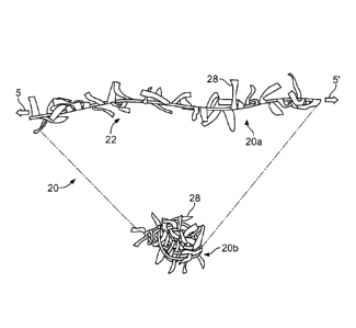
[0049] With reference to FIG. 2, an example occlusion device 20 includes a
wire
(not visible) covered by a membranous material 22. The example occlusion
device 20 is depicted in a low-profile delivery configuration. That is,
example
occlusion device 20 is in a low-profile configuration (by virtue of stretching
forces 5
and 5') as used when delivering example occlusion device 20 via a delivery
catheter
or sheath. Upon emergence from the delivery catheter or sheath, the example
occlusion device 20 would seek a relaxed configuration analogous to the coiled
relaxed configuration 10a of FIG. 1 (or another configuration depending on the
type
of occlusion device).
[0050] The flexible membranous materials used for the occlusion devices
provided
herein may have pores that are sized to substantially (or, in some embodiments
completely) prevent the passage of bodily fluids and emboli through the
membranous materials. In some embodiments, the membranous materials have a
microporous structure that provides a tissue ingrowth scaffold for durable
occlusion
and supplemental anchoring strength of the occlusion devices in a bodily
lumen,
cavity, vessel or organ. In some embodiments, the membranous materials are
configured such that the inhibition of fluid passage through the membranous
sheet
material is immediate and does not rely on a thrombotic process. In some
embodiments, the membranous materials initiate a cascade of thrombosis, such
that
the final occlusive effect is attained by a combination of inhibition of fluid
passage by
the membranous material and the blood's own natural thrombetic process.
[0051] In general, the flexible membranous materials can comprise any
suitable
biocompatible material. Suitable materials include, but are not limited to,
porous or
non-porous synthetic polymers such as polyethylene, polypropylene,
polyurethane,
polyglycolic acid, polyesters, polyamides, polyesters such as polyethylene
terephthalate, polyaramids, polyfluorocarbons such as fluorinated ethylene
propylene (FEP), perfluorinated alkoxy (PFA), polytetrafluoroethylene (PTFE),
and
expanded polytetrafluoroethylene (ePTFE), and their mixtures, blends and
copolymers. ePTFE materials are described in U.S. Pat. Nos. 3,953,566 and
4,187,390. A suitable
ePTFE polymeric sheet material is taught by US 5,814,405.
In some embodiments, the membranous materials are
bioresorbable or bioabsorbable materials, such as bioresorbable or
bioabsorbable
CA 02860582 2014-07-03
WO 2013/106694
PCT/US2013/021209
13
polymers. In some embodiments, the membranous materials are formed of a
copolymer. In some embodiments, a first portion of the membranous material of
an
occlusion device is formed of a first material and a second portion of the
membranous sheet material of the device is formed of a second material. For
example, the portion of the membranous material that covers a wire of the
device
may be formed of a first material, and the remaining portions of the
membranous
sheet material of the device may be formed of a second material. In some
embodiments, three or more types of membranous materials are used on a single
occlusion device.
[0052] Any suitable type of construction of the membranous material can be
used
for the occlusion devices provided herein. In some embodiments, the membranous
material has a knitted construction. In some embodiments, the membranous
material has a woven construction. In some embodiments, the membranous
material has a mesh construction. In some embodiments, the membranous material
has a film construction. In some embodiments, a combination of construction
types
are included in a single occlusion device. In some embodiments, multiple
layers of
dissimilar types of membranous materials and/or types of constructions are
included
in a single occlusion device. In some embodiments, the membranous materials
include hairs or filaments of membranous material attached to the surface of
the
membranous material. In some such embodiments, the hairs or filaments can
increase the thrombogenicity of the membranous material.
[0053] In some embodiments, the membranous materials are made in sheet or
strip form. In some embodiments, the membranous materials are subsequently
wound, knitted or woven into a tube form. In some embodiments, the membranous
materials are made in filament or thread form, and are subsequently wound,
knitted
or woven into a sheet, strip or tube form. In some embodiments, the membranous
materials are extruded as a sheet, strip, or tube form.
[0054] Some embodiments of the membranous materials are made by a spinning
process. Some embodiments of spun membranous materials are made in sheet
form. Some embodiments of spun membranous materials are made in tube form, for
example by spinning materials onto a mandrel. Various spinning processes can
be
used, including: wet spinning, dry spinning, melt spinning, extrusion
spinning, direct
CA 02860582 2014-07-03
WO 2013/106694
PCT/US2013/021209
14
spinning, gel spinning, and electro-spinning, to name a few examples. In some
embodiments, spinning processes provide membranous materials that include
micro
or nano filaments.
[0055] In some embodiments, the membranous materials used in the occlusion
devices provided herein are modified by one or more chemical or physical
processes
that enhance certain properties of the membranous materials. For example, in
some
embodiments, a hydrophilic coating is applied to the membranous sheet
materials to
improve the wettability and echo translucency of the membranous materials. In
some embodiments the membranous materials are modified with chemical moieties
that promote one or more of endothelial cell attachment, endothelial cell
migration,
endothelial cell proliferation, and resistance to or promotion of thrombosis.
In some
embodiments the membranous materials are modified with one or more covalently
attached drug substances (e.g., heparin, antibiotics, and the like) or
impregnated
with the one or more drug substances. The drug substances can be released in
situ
to promote wound healing, reduce tissue inflammation, reduce or inhibit
infections,
and to promote various other therapeutic treatments and outcomes. In some
embodiments the drug substance is a corticosteroid, a human growth factor, an
anti-
mitotic agent, an antithrombotic agent, a stem cell material, or dexamethasone
sodium phosphate, to name some examples. Coatings and treatments may be
applied before or after the membranous material is affixed or disposed on the
wire of
the occlusion devices. Additionally, one or both sides of the membranous
material
may be coated. In some embodiments, certain coatings and/or treatments are
applied to the membranous material located on some portions of an occlusion
device, and other coatings and/or treatments are applied to the membranous
material located on other portions of the occlusion devices. In some
embodiments, a
combination of multiple coatings and/or treatments are applied to the
membranous
materials. In some embodiments, certain portions of the device are left
uncoated
and/or untreated.
[0056] In some embodiments, the membranous materials used for the occlusion
devices herein are an elastomeric film material. That is, in some embodiments
the
membranous sheet materials can stretch and rebound to accommodate the
movement of the wires during reconfiguration of the occlusion devices, such as
between the low-profile and the relaxed configurations. Such elasticity of the
CA 02860582 2014-07-03
WO 2013/106694
PCT/US2013/021209
membranous materials can, in some embodiments, advantageously facilitate the
reconfiguration of the occlusion devices without ancillary stress relief
measures
(such as incisions to the membranous material).
[0057] Still referring to FIG. 2, the membranous material 22 is applied to
the wire
10 of the example occlusion device 20. In some embodiments, the membranous
material 22 is applied to the wire 10 so that the membranous material 22
creates a
wire sleeve portion and a fringe 26 portion. For example, in some embodiments
membranous material 22 is an elongate strip of material that is folded around
the
wire 10 to form the wire sleeve 24, and the length-wise free ends of the strip
are
affixed to each other to form the fringe 26. In some embodiments, the free
ends of
the membranous material 22 are affixed to each other using a fluorinated
ethylene
propylene (FEP) coating or film. In some embodiments, the free ends of the
membranous material 22 are affixed to each other by stitching,
welding/bonding,
using various biocompatible adhesives, or by other suitable methods or a
combination of methods. By folding the strip of membranous material 22 over
the
wire 10, the wire 10 can be fully or partially covered by the membranous
material 22.
In some embodiments, a portion of the wire 10 can be exposed, i.e., a portion
of the
wire 10 may not be covered by membranous material 22. For example, in some
embodiments, the ends of the wire 10 are exposed.
[0058] In some embodiments, the membranous material 22 is applied to the
wire
10 by winding it around the wire 10. In some embodiments the diameter of the
wound membranous material 22 is greater than the diameter of the wire 10 so
that a
fringe 26 can be formed. The fringe 26 can be formed by flattening the excess
membranous material (material that remains after covering the wire) and
affixing the
flattened layers to each other.
[0059] In some embodiments, the wire 10 and the fringe 26 are about the
same
length (with the length being measured along the axis of the wire 10). In some
embodiments, the fringe 26 extends past the ends of the wire 10 so that the
fringe 26
is longer than the wire 10. In some embodiments, the fringe 26 extends past
the
wire 10 on just one end of the wire 10. In some embodiments, the fringe 26
extends
past the wire 10 on both ends of the wire 10.
CA 02860582 2014-07-03
WO 2013/106694
PCT/US2013/021209
16
[0060] In some embodiments, the wire 10 is not located along an edge of the
membranous material 22. In some embodiments, the wire 10 is positioned about
in
the middle of one or more strips of membranous material 22. In some such
embodiments, two or more fringe 26 portions are created¨with the wire 10 in
between the fringe portions. While in some embodiments, the two or more fringe
26
portions have individual fringes 28 of approximately the same length, in some
embodiments the two or more fringe 26 portions have individual fringes 28 of
different lengths.
[0061] In some embodiments, the wire 10 is positioned off-center on (or
between)
one or more strips of membranous material 22 (but not at an edge). In some
such
embodiments, two or more fringe 26 portions with unequal transverse lengths
are
formed. In some embodiments, the wire 10 is positioned on or between layers of
membranous strips and the wire 10 has a pattern that is not substantially
linear. In
some such embodiments, two or more fringe 26 portions with variable and
unequal
lengths are formed.
[0062] In some embodiments, the wire 10 has an adhesive coating to assist
in the
application of the membranous material 22 to the wire 10, and to affix the
wire 10 to
the membranous material 22. For example, in some embodiments the adhesive on
the wire 10 is FEP, applied by a powder coating process. In some embodiments,
other biocompatible adhesives are used on the wire 10 in addition to or in
place of
FEP. The adhesive on the wire 10 can cover the entire wire 10, or be in
certain
discrete locations on the wire 10.
[0063] In some embodiments, the membranous material 22 has adhesive
properties. In some embodiments, a FEP coating or FEP film layer is applied to
all
or portions of the membranous material 22. In some embodiments, the adhesives
are heat-activated. In some embodiments, various other biocompatible adhesives
are incorporated within or on the surface of the membranous material 22. The
adhesives can assist in attaching the membranous material 22 to the wire 10,
as well
as in adhering layers of the membranous material 22 to each other.
[0064] In addition to or instead of adhesives, any other suitable method
for affixing
the wire 10 to the membranous material 22 can be used. For example, in some
CA 02860582 2014-07-03
WO 2013/106694
PCT/US2013/021209
17
embodiments, the wire 10 is affixed to the membranous material 22 using
stitching.
In some embodiments, the wire 10 has a textured surface, or textured surface
portions, to create a grip between the wire 10 and the membranous material 22.
In
some embodiments, the wire 10 has barbs or protrusions that penetrate the
membranous material 22 to affix the two together. In some embodiments, the
wire
has portions with a larger cross-sectional profile to create an interference
fit
between the wire 10 and the sleeve 24 at certain locations. In some
embodiments,
the fit between the entire length of the wire 10 and the sleeve 24 is an
interference
fit. In some embodiments, the fit between the entire length of the wire 10 and
the
wire sleeve 24 is a line-to-line fit.
[0065] A variety of other relationships between the wire 10 and the
membranous
material 22 are also envisioned. For example, in some embodiments the
dimensional fit between the wire 10 and the wire sleeve 24 of the membranous
material 22 is a slip fit along the entire length of the wire 10. In some
embodiments,
the wire 10 is not affixed to the membranous material 22. In some embodiments,
ends of the wire 10 are doubled-over and crimped to pinch and capture the
membranous material 22. Alternatively, the membranous material 22 can extend
beyond the end of wire 10.
[0066] In some embodiments, the wire 10 is affixed to the membranous
material
22 by weaving the wire 10 through the membranous material 22. In some such
embodiments, one or more layers of membranous sheet material 22 can be
included.
[0067] In some embodiments of the occlusion devices provided herein, one or
more radiopaque markers are included. The radiopaque markers can assist with
the
radiographic visualization of the occlusion devices¨which can be beneficial
during
the implantation procedure. In some embodiments, the radiopaque markers are
affixed at one or more locations on the membranous material. In some
embodiments, the radiopaque markers are integral portions of the membranous
material. In some embodiments, the radiopaque markers are affixed at one or
more
locations on the one or more wires. In some embodiments, the radiopaque
markers
are integral portions of the one or more wires. In some embodiments, the
radiopaque markers are located at one or more locations on both the membranous
CA 02860582 2014-07-03
WO 2013/106694
PCT/US2013/021209
18
sheet and the one or more wires. In some embodiments, the membranous material
is wetted with contrast solution prior to deployment to provide enhanced
radiopacity
during the deployment procedure.
[0068] In some embodiments, the fringe 26 portion(s) are initially a
material that is
non-integral to the membranous material elsewhere on an occlusion device
(e.g.,
sleeve 24). In some such embodiments, the fringe 26 can be, for example,
affixed to
the other membranous material as a step in the process of manufacturing an
occlusion device. The fringe 26 can be affixed to the membranous material
using
any suitable method such as by using adhesives, stitching, welding, bonding,
and
the like. In some such embodiments, the fringe 26 can be a dissimilar material
(in
comparison to the membranous material elsewhere on the occlusion device). In
some embodiments, the material of the fringe 26 can be selected to provide
desirable properties and features particularly suited for individual fringes
28, whereas
the membranous material elsewhere on the device can be selected to provide
properties and features particularly suited for those locations. In some
embodiments, the individual fringes 28 are made to be stiffer than the
membranous
material used elsewhere on the device (to name one example). In some
embodiments, non-integral membranous material is the same type of material as
used elsewhere on the occlusion device 20.
[0069] Still referring to FIG. 2, individual fringes 28 can be formed by
incising or
cutting the fringe 26 portion(s) of the membranous material 22 (as represented
by
the transverse cut-lines projecting from the wire sleeve 24). The cuts to the
fringe 26
create multiple individual fringes 28 of membranous material. In some
embodiments, the fringe 26 cuts are made approximately in a radial or
orthogonal
direction in relation to the wire 10. In some embodiments, the fringe 26 cuts
are
made at non-orthogonal angles in relation to the wire 10. In some embodiments,
a
combination of orthogonal and non-orthogonal cuts (in relation to the wire 10)
are
used. Therefore, in some embodiments the individual fringes 28 are generally
rectangular-shaped. In some embodiments, the individual fringes 28 are
triangular
or shaped like trapezoids. In some embodiments, the individual fringes 28 are
irregularly shaped. In some embodiments, the individual fringes 28 of an
occlusion
device are a variety of such shapes and irregular shapes.
CA 02860582 2014-07-03
WO 2013/106694
PCT/US2013/021209
19
[0070] With reference to FIG. 3, the example occlusion device 20 is
illustrated in a
low-profile delivery configuration 20a and a relaxed configuration 20b
(depending on
presence or absence of stretch forces 5 and 5'). The multiple individual
fringes 28
are now distinctly visible. The individual fringes 28 can also be considered
as
membranous strips, strands, ribbons, fingers, filaments, projections,
bristles, free
ends, frayed portions, hairs, and the like. In some embodiments, the
individual
fringes 28 perform various beneficial functions for occlusion devices. For
example,
when the occlusion device 20 is implanted in a bodily lumen, cavity, vessel,
or organ,
the individual fringes 28 may provide fluid flow obstructions, cavity filler
material,
tissue ingrowth scaffolding, thrombogenicity elements, and the like. In
addition, in
some embodiments the individual fringes 28 provide a stress relief function
that is
beneficial when the wire is transitioned between its low-profile delivery and
its
relaxed configurations. That is, the individual fringes 28 can tend to reduce
some
external forces that the membranous sheet 22 may otherwise exert on the wire
10 as
the wire changes shapes. When occlusion device 20 is implanted in a bodily
lumen,
cavity, vessel, or organ, occlusion device 20 approximately takes on the
configuration of relaxed configuration 20b.
[0071] The individual fringes of the occlusion devices provided herein can
have
any suitable length. In some embodiments, the fringes are about 2.50 mm to
12.70
mm long, but in other embodiments fringes with shorter or longer lengths are
used.
For example, embodiments using spun membranous materials can include fringes,
hairs, or filaments in the nano range. It should be understood that fringes of
any
suitable length are envisioned within the scope of this document. In some
embodiments, the fringes have a substantially consistent length on the entire
occlusion device. In some embodiments, the fringes have variable lengths at
different locations on the occlusion device. For example, in some embodiments
the
fringes are longer near the middle of the occlusion device than at the ends of
the
occlusion device. In some embodiments the fringes are shorter near the middle
of
the occlusion device than at the ends of the occlusion device. In some
embodiments, the lengths of the fringes vary approximately according to a
pattern
(e.g., a sinusoidal wave or other pattern). In some embodiments, the lengths
of the
fringes are randomly variable.
CA 02860582 2014-07-03
WO 2013/106694
PCT/US2013/021209
[0072] Individual fringes of the occlusion devices provided herein can be
formed to
have a variety of widths or diameters. In some embodiments, the widths or
diameters of the fringes are about 0.50 mm to 2.50 mm, but in other
embodiments
fringes having wider or narrower widths or diameters are used. It should be
understood that fringes of any suitable width or diameter are envisioned
within the
scope of this document. In some embodiments, the fringes have a substantially
consistent width or diameter on the entire occlusion device. In some
embodiments,
the fringes have variable widths or diameters at different locations on the
occlusion
device. For example, in some embodiments the fringes are wider near the middle
of
the length of the occlusion device than at the ends of the occlusion device.
In some
embodiments, the fringes are narrower near the middle of the length of the
occlusion
device than at the ends of the occlusion device. In some embodiments, the
widths
or diameters of the fringes vary approximately according to a pattern along
the
length of the wire. In some embodiments, the widths or diameters of the
fringes are
randomly variable.
[0073] With reference to FIG. 4, an example occlusion device 40 is
illustrated in its
delivery configuration 40a and its relaxed configuration 40b. The example
occlusion
device 40 includes a membranous tube 42 and one or more wires 10. The natural
relaxed (or shape-memory) configuration of wire 10 is a coiled configuration
(see,
e.g., FIGS. 6A-6F). Therefore, for occlusion device 40 to be in the delivery
configuration 40a requires the application of external force(s), such as
stretching
forces 5 and 5'. The elimination or substantial reduction of stretching forces
5 and 5'
allows the occlusion device 40 to coil into its relaxed configuration 40b.
Configuration 40b is approximately the configuration that the occlusion device
40 will
assume when it is implanted in a bodily lumen, cavity, vessel, or organ.
[0074] The materials and methods of construction of occlusion device 40 are
generally analogous to the materials and methods of construction of occlusion
device 20 described above. For example, membranous tube 42 can be constructed
using any of the materials, material treatments, and manufacturing methods
described above in regard to membranous materials and tubes. In addition, wire
10
can be constructed using any of the materials, material treatments, and
manufacturing methods described above. Further, the membranous tube 42 and
CA 02860582 2014-07-03
WO 2013/106694
PCT/US2013/021209
21
wire 10 can be affixed to each other using any of the methods described above
for
affixing a membranous sheet to a wire.
[0075] However, differences exist between occlusion device 40 illustrated
in FIG.
4 and occlusion device 20 described above. For example, in some embodiments
the
diametric size difference between the membranous tube 42 and wire 10 is
greater
than the diametric size difference between sleeve 24 and the wire 10 of
occlusion
device 20. In some embodiments, the size difference between the membranous
tube 42 and wire 10 allows the wire 10 to take the form of a helix within the
membranous tube 42 when the occlusion device 40 is in the delivery
configuration
40a. In some embodiments, the wire 10 takes non-linear forms other than a
helix
within the membranous tube 42, when the occlusion device 40 is in the delivery
configuration 40a. In some embodiments, the wire 10 is substantially linear
within
the membranous tube 42.
[0076] Further, in some embodiments example occlusion device 40 does not
include fringes like occlusion device 20. Rather, the membranous tube 42
becomes
bunched or gathered together when the occlusion device 40 is configured in its
relaxed configuration 40b. The membranous tube 42 in its bunched together
arrangement can provide the occlusive properties as well as other properties
that are
desirable for an occlusion device.
[0077] With reference to FIG. 5, another example occlusion device 50 is
illustrated
in its delivery configuration 50a and its relaxed configuration 50b. The
example
occlusion device 50 includes a membranous tube 52 and one or more wires 10.
The
relaxed (or shape-memory) configuration of wire 10 is a coiled configuration
(see,
e.g., FIGS. 6A-6F). Therefore, for occlusion device 50 to be in the delivery
configuration 50a requires the application of external force(s), such as
stretching
forces 5 and 5'. The elimination or reduction of stretching forces 5 and 5'
allows the
occlusion device 50 to coil into its relaxed configuration 50b. Configuration
50b is
approximately the configuration that the occlusion device 50 will assume when
it is
implanted in a bodily lumen, cavity, vessel, or organ.
[0078] Example occlusion device 50 includes the features of example
occlusion
device 40 described above. In addition, occlusion device 50 includes
individual
CA 02860582 2014-07-03
WO 2013/106694
PCT/US2013/021209
22
fringes 58. In general, the individual fringes 58 can be constructed and can
include
the features described above in reference to fringes 28.
[0079] In some embodiments, the individual fringes 58 can be formed by
making
multiple transverse cuts to the membranous tube 52 (fringe cut-lines are
represented
by the substantially radial lines shown in delivery configuration 50a). In
some
embodiments, individual cuts are not made fully around the circumference of
the
membranous tube 52. That is, an individual cut does not fully sever a portion
of the
membranous tube 52 so as to create multiple tubes. For example, in some
embodiments the portions of the membranous tubes 52 adjacent to the wire 10
are
not cut.
[0080] When occlusion device 50 is allowed to assume its relaxed
configuration
50a, the individual fringes 58 can project from the coiled wire 10 so as to
create a
larger profile as compared to similar occlusion devices without fringes 58.
The
larger profile can be advantageous for certain implementations of an occlusion
device.
[0081] FIGS. 6A-6F illustrate example wire coil shape embodiments. The coil
shapes shown are approximately in their relaxed configurations. However, in
some
examples the coils are enlarged or elongated to assist with the visualization
of the
configuration of the coil shape. The example coil shapes provided have shapes
and
properties that can be mixed and matched in any combination to provide the
desired
shape and properties of the wires for various embodiments of the occlusion
devices
provided herein.
[0082] FIG. 6A illustrates a generally helical coil 60 that is similar to
the relaxed
configuration 10a of FIG. 1. The generally helical coil 60 is made from wire
61. The
generally helical coil 60 includes ends 62 and 62'. The ends 62 and 62' are
made by
doubling over the wire 61. This has the effect of making ends 62 and 62' more
bluntly-shaped than the ends 62 and 62' would be if the wire was not doubled
over.
Such blunt ends are desirable in some occlusion device embodiments. In some
embodiments, the ends of the wire can be made blunt by other techniques, such
as
by adding bulbous tips to the ends of the wire.
CA 02860582 2014-07-03
WO 2013/106694
PCT/US2013/021209
23
[0083] FIG. 6B illustrates a triangular coil 63. In some embodiments, the
coils
such as triangular coil 63 (and the others described herein) can be formed by
winding the wire 61 onto a mandrel that defines the general shape of the coil
being
made. For example, triangular coil 63 can be formed by wrapping the wire 61 in
a
triangular pattern on a suitable mandrel. In some embodiments, a super-elastic
shape memory alloy wire can be used, and the wire can be heat-set into the
pattern
it acquired as a result of being wound onto a mandrel.
[0084] FIG. 60 illustrates a double coil 65. Double coil 65 includes wires
61 and
64 that are wound on the same axis, in the same direction, and using the same
pitch.
In the embodiment shown, the wires 61 and 64 operate in conjunction with each
other like two strands of a stranded wire. While double coil 65 has side-by-
side
wires 61 and 64, in some embodiments the wires can be twisted together or
otherwise entangled with each other. In some embodiments, the wires 61 and 64
can be incongruent, have different pitches, or be on different axes. In some
embodiments, such multiple stranded constructions can provide a coil with
enhanced
capabilities to be elastically deformed, while also providing a stronger bias
to seek
the relaxed configuration as compared to a single wire. In some embodiments,
more
than two wires are used in a coil embodiment.
[0085] FIG. 6D illustrates another coil 66 that is made of more than one
wire. Coil
66 includes wires 61 and 64. In this embodiment, one wire is wound using a
right-
handed helix and the other wire is wound using a left-handed helix. Both are
wound
on the same axis. In some embodiments, the wires can be wound on different
axes.
In some embodiments, the wires 61 and/or 64 comprise multiple stranded wires
such
as side-by-side wires as shown.
[0086] FIG. 6E illustrates a randomized coil 67. In this embodiment, the
turns of
wire 61 are wound at various coil diameters, axes, pitches, and so on. This
randomized configuration can provide enhanced occlusion in some
implementations.
[0087] FIG. 6F illustrates a conical coil 68. In this embodiment, the wire
61 is
wound with an increasingly larger outer diameter for each coil turn, while on
the
same axis. This conical coil 68 configuration can provide enhanced occlusion
at the
center area of the occlusion device in some implementations.
CA 02860582 2014-07-03
WO 2013/106694
PCT/US2013/021209
24
[0088] With reference to FIG. 7, a wire frame 70 of an example cup-shaped
occluder embodiment is depicted in a relaxed configuration 70a and a delivery
configuration 70b (again depending on presence or absence of stretch forces 5
and
5'). In general, wire frame 70 is a component of an example occlusion device
embodiment that also includes a membranous material (see, e.g., FIGS. 8 and
9).
[0089] In the illustrated embodiment the wire frame 70 includes two (2)
portions.
The first portion is a cup frame 72. The second portion is a coil portion 74
(shown in
a relaxed configuration 74a and a low-profile configuration 74b). In some
embodiments, the wire frame 70 is made of a single wire 71. In some
embodiments,
the wire frame 70 is made of two or more wires. When two or more wires are
used,
they may or may not be coupled together. In some embodiments, the wire frame
includes three or more portions. The wire 71 has the properties and features
of the
wires described above.
[0090] In some embodiments, the wire frame 70 includes the cup frame 72
portion, but no coil portion 74 is included. In some such embodiments, the
occluder
device embodiment includes a membranous cup portion and does not include an
additional membranous occluder portion (i.e., portion 74 of FIG. 8 and portion
96 of
FIG. 9 is not included).
[0091] The cup frame 72 is generally shaped like a wire-framed open
cylinder. In
some embodiments, the cup frame 72 can be formed by bending a wire 71 in an
undulating or serpentine fashion (e.g., a generally sinusoidal pattern, U-
shaped, V-
shaped, ovaloid-shaped, and the like) around a cylindrical mandrel. An open
lumen
in the interior of the wire-framed cylinder is created, and the ends of the
wire-framed
cylinder are open.
[0092] The cup frame 72 is formed so that it can be radially compressed to
a low-
profile configuration for placement in a delivery catheter or sheath (as will
be
described further below in reference to FIGS. 10A-10D).
[0093] The coil portion 74 of wire frame 70 generally includes the
properties and
features of wires 10, 10, 10, and 61 described above. In some embodiments,
coil
portion 74 is made from a wire 71 that is also used to form the cup frame 72.
CA 02860582 2014-07-03
WO 2013/106694
PCT/US2013/021209
[0094] With reference to FIG. 8, an example cup-shaped occlusion device 80
includes a wire 71 and a membranous tube 82. The example cup-shaped occlusion
device 80 is shown in a low-profile configuration 80a and a relaxed
configuration 80b
(again depending on presence or absence of stretch forces 5 and 5').
[0095] Wire 71 of example cup-shaped occlusion device 80 can be configured,
for
example, as the wire frame 70 described in reference to FIG. 7. That is, in
some
embodiments wire 71 can have a cup frame portion 72 and a coil portion 74. A
membranous tube 82 can be affixed to wire 71, continuously or intermittently,
using
any of the variety of methods described above (e.g., adhesives, stitching,
friction,
weaving, interference, etc.).
[0096] The membranous tube 82 can be constructed using any of the
materials,
treatments, and manufacturing methods described above in regard to membranous
materials. For example, in some embodiments, the membranous tube 82 is an
extruded polymeric film tube. In some embodiments, the membranous tube 82 is a
helically-wound strip of membranous material. In some embodiments, the
membranous tube 82 has a woven or knitted construction.
[0097] Membranous tube 82 includes a distal end 83 and a proximal end 84.
The
proximal end 84 is a closed end of the membranous tube 82. In some
embodiments,
the distal end 83 is an open end of the membranous tube 82. In some
embodiments, the distal end 83 is a closed end of the membranous tube 82.
[0098] A membranous cup portion 85 is located at the proximal end 84. In
some
embodiments, the membranous cup portion 85 can be formed by simply gathering
and cinching the membranous tube 82 at the proximal end 84. A clip device,
purse
string sutures, or similar methods can be used to cinch closed the membranous
tube
82 to create the cup portion 85. In some embodiments, the membranous cup
portion
85 can be sewn or cohered to create a conical, semispherical, cylindrical, or
other
similar three-dimensional cup-like shape.
[0099] As will be described further in reference to FIG. 10D, when the
example
cup-shaped occlusion device 80 is implanted at a desired target site within a
bodily
lumen, cavity, vessel, or organ (for example, to treat endoleaks), the
membranous
cup portion 85 will be everted within the interior of cup frame 72. In that
CA 02860582 2014-07-03
WO 2013/106694
PCT/US2013/021209
26
configuration, the cup portion 85 will be positioned to occlude or reduce the
passage
of fluids through the vessel or cavity.
[00100] With reference to FIG. 9, an example cup-shaped occlusion device 90
includes a wire 71 and a membranous tube 92. The membranous tube 92 includes a
distal end 93 and a proximal end 94. The example cup-shaped occlusion device
90
is shown in a low-profile configuration 90a and a relaxed configuration 90b
(again
depending on presence or absence of stretch forces 5 and 5').
[00101] Example cup-shaped occlusion device 90 includes the properties and
features of the example cup-shaped occlusion device 80 described above. In
addition, example cup-shaped occlusion device 90 includes individual fringes
98.
[00102] In some embodiments the individual fringes 98 can be formed by making
multiple transverse cuts to the membranous tube 92 in the distal portion 96.
Fringe
cut-lines are represented by the substantially radial lines shown in the low-
profile
configuration 90a. As with the embodiment described above in reference to FIG.
5,
the individual cuts are not made fully around the circumference of the
membranous
tube 92. That is, an individual cut does not fully sever a portion of the
membranous
tube 92 so as to create multiple tubes. For example, in some embodiments the
portions of the membranous tube 92 that are adjacent to the wire 71 are not
cut. In
some embodiments, the portions of the membranous tube 92 that (i) covers the
wire
cup frame and (ii) forms the membranous cup portion 95 are also not cut to
create
fringes.
[00103] When occlusion device 90 is allowed to assume its relaxed
configuration
90a, the individual fringes 98 can project from the distal portion 96 so as to
create a
larger profile as compared to similar occlusion devices without fringes 98.
The
larger profile can be advantageous for certain implementations that are suited
to
having a higher occlusive and/or thrombogenicity properties.
[00104] FIGS. 10A-10D provide a series of illustrations to depict an example
method of deploying an example cup-shaped occlusion device 90 within a vessel
110 using an example deployment system 100. The vessel 110 has a fluid (e.g.,
blood) flowing through it in a direction indicated by arrow 120, i.e., arrow
120 points
in a distal direction. Therefore, the direction opposite of arrow 120 is the
proximal
CA 02860582 2014-07-03
WO 2013/106694
PCT/US2013/021209
27
direction. The example cup-shaped occlusion device 90 is the occlusion device
described in reference to FIG. 9 above. However, other types of occlusion
devices
can be deployed using the methods provided here (or by using minor variations
of
the methods). The example delivery system 100 generally includes a delivery
sheath (or catheter) 102 and a pusher catheter 104.
[00105] In FIG. 10A, the example deployment system 100 containing the example
cup-shaped occlusion device 90 is depicted as approaching an implantation site
within the vessel 110. The deployment system 100 includes a delivery catheter
or
sheath 102. In some embodiments, the delivery sheath 102 is a tube that is
used to
constrain an occlusion device in its low-profile delivery configuration, and
to
percutaneously deliver the occlusion device to a target deployment site within
a
bodily cavity or vessel. The tubular delivery sheath 102 can have a circular
cross-
section or another cross-sectional shape, such as ovular or other suitable
shapes. A
proximal end of the delivery sheath 102 can be attached to a deployment
actuator
(e.g., a handheld deployment actuator or a non-handheld deployment actuator)
that
can be operated by a clinician operator. In some embodiments, the deployment
actuator provides one or more controls that permit a clinical operator to
control one
or more aspects of the delivery sheath 102. In some embodiments, the delivery
sheath 102 is a steerable delivery sheath. In some embodiments, at least the
distal
end portion of the delivery sheath 102 is steerable. In some embodiments, a
guidewire is installed in the patient first, and the delivery sheath 102 is
installed over
the guidewire. The delivery sheath 102 can have one lumen or multiple (e.g.,
two or
more) lumens. In some embodiments, radiopaque markers are included on portions
of the delivery sheath 102 (e.g., the tip) to assist with radiographic
visualization of
the delivery sheath 102 during the installation of the delivery sheath 102
into the
body of a patient.
[00106] The delivery sheath 102 contains the example cup-shaped occlusion
device 90. At this stage of the deployment process the cup-shaped occlusion
device
90 is in a low-profile delivery configuration so as to fit within a lumen of
the delivery
sheath 102. To achieve the low-profile delivery configuration, the coil
portion 74 is
stretched axially to elongate the coil and to reduce its radial profile, and
the cup
frame 72 is radially compressed to reduce its radial profile. Once the
occlusion
device 90 resides within the delivery sheath 102, the delivery sheath 102
exerts
CA 02860582 2014-07-03
WO 2013/106694
PCT/US2013/021209
28
containment forces on the occlusion device 90 to retain the occlusion device
90 in its
low-profile delivery configuration.
[00107] The example deployment system 100 also includes a pusher catheter 104.
In some embodiments, the pusher catheter 104 is a flexible polymeric tubular
component. The pusher catheter 104 is located within a lumen of the delivery
sheath 102. In some embodiments, the distal end of the pusher catheter 104 is
releasably coupled to the occlusion device 90. In some embodiments, the
proximal
end of the pusher catheter 104 is coupled to a deployment actuator, and the
deployment actuator provides one or more controls that permit a clinical
operator to
control one or more aspects of the pusher catheter 104. In other deployment
system
embodiments, other types of devices for constraining and remotely deploying an
occlusion device (other than a pusher catheter) can be used.
[00108] In some embodiments, the pusher catheter 104 is releasably coupled to
a
connector element of the occlusion device 90. In some embodiments, the pusher
catheter 104 is releasably coupled to the membranous sheet or wire portions of
the
occlusion device 90. In some embodiments, the pusher catheter 104 contains a
looped suture, clip, clamp, or similar structure that releasably couples the
pusher
catheter 104 to the occlusion device 90. In some embodiments, the looped
suture or
similar structure is radiopaque.
[00109] In some embodiments, the pusher catheter 104 includes two or more
lumens through which the looped suture 106 passes. That is, one portion of the
looped suture 106 can pass through a first lumen in the pusher catheter 104
and a
second portion of the looped suture 106 can pass through a second lumen in the
pusher catheter 104. In some embodiments, the looped suture 106 can pass
through a single lumen in the pusher catheter 104. In some embodiments, the
looped suture 106 is a strand of suture material that is used to releasably
couple the
pusher catheter 104 to the occlusion device 90 by tethering them together. For
example, the pusher catheter 90 of FIG. 10A illustrates a looped suture 106
attached
to the membranous sheet of the occlusion device 90. In some embodiments, the
looped suture 106 is a single length of suture material with both ends of the
looped
suture 106 located at the proximal end of the deployment system 100, such as
at or
near the deployment actuator coupled to the deployment system 100. In some
CA 02860582 2014-07-03
WO 2013/106694
PCT/US2013/021209
29
embodiments, the looped suture 106 is routed from the proximal end of the
deployment system 100, through a first lumen in the pusher catheter 104,
exiting the
first lumen at the distal end of the pusher catheter 104, coupling to the
medical
device, re-entering the distal end of the pusher catheter 104 via a second
lumen, and
running back through the second lumen to the proximal end of the deployment
system 100. The clinician operator can tug on the ends of the looped suture
106 to
snug the pusher catheter 104 to the occlusion device 90. When the pusher
catheter
104 is snugged to the occlusion device 90, movement of the pusher catheter 104
will
tend to induce a corresponding movement of the occlusion device 90. In some
embodiments, one or both ends of the looped suture 106 are coupled to the
deployment actuator, which may provide one or more controls permitting the
clinical
operator to control one or more aspects of the occlusion device 90.
[00110] In FIG. 10B, the delivery sheath 102 has been partially pulled back
(translated proximally) while the pusher catheter 104 has been maintained
substantially stationary. This relative movement between the delivery sheath
102
and the pusher catheter 104 has caused the distal portion 96 of the occlusion
device
90 to emerge from the lumen of the delivery sheath 102. With the containment
forces of the delivery sheath 102 on the distal portion 96 substantially
removed, the
distal portion 96 is freed to self-expand to seek its relaxed configuration.
In turn, the
distal portion 96 can contract axially and expand radially as the wire in the
distal
portion 96 seeks its natural relaxed coiled shape. In its relaxed state,
distal portion
96 is radially expanded to entirely or partially fill the lumen of vessel 110.
[00111] In some deployment method implementations, the pusher catheter 104 can
be pushed distally while the delivery sheath 102 is maintained substantially
stationary. That relative movement between the delivery sheath 102 and the
pusher
catheter 104 can cause the distal portion 96 of the occlusion device 90 to
emerge
from the lumen of the delivery sheath 102, similarly to the method of pulling
back the
delivery sheath 102 described above. In some deployment method
implementations,
a combination of the two methods are used.
[00112] In FIG. 100, the delivery sheath 102 has been further pulled back
proximally while the pusher catheter 104 has been maintained substantially
stationary. This relative movement between the delivery sheath 102 and the
pusher
CA 02860582 2014-07-03
WO 2013/106694
PCT/US2013/021209
catheter 104 has caused the entire occlusion device 90 to emerge from the
lumen of
the delivery sheath 102. With the containment forces of the delivery sheath
102 on
the occlusion device 90 removed, the cup frame 72 is freed to self-expand to
seek its
relaxed configuration. In turn, the cup frame 72 can expand radially as the
wire in
the cup frame 72 seeks its natural relaxed shape. In its relaxed state, the
cup frame
72 can radially expand to fully or partially become adjacent to the inner
walls of
vessel 110. The membranous cup portion 95 of the occlusion device 90 is also
emerged from the delivery sheath 102 at this stage.
[00113] At this stage of the deployment process, the clinician operator can
confirm
the desirability of the position of the occlusion device 90 in relation to the
surrounding bodily tissue. In some cases, clinicians use magnetic resonance
imaging (MRI) or x-ray fluoroscopy imaging to visualize the positioning of the
occlusion device 90. In general, the clinician may be interested in one or
more of the
position, location, orientation, anchoring strength, and the sealing
properties of the
occlusion device 90 in relation to the surrounding tissue. In some
embodiments,
radiopaque markers or jackets can be included on the occlusion device 90, such
as
on the wire and/or on the membranous material. In some embodiments that
include
a radiopaque looped suture 106, the adequacy of the fixation of the occlusion
device
90 can be confirmed by inducing slack in the looped suture 106 and using
radiography to visualize that the slack is maintained over a period of time.
[00114] In some implementations, to simulate the likely position that the
occlusion
device 90 may take after being released from the looped suture 106, the
clinician
operator may loosen, but not fully release, the looped suture 106 from its
hold on the
occlusion device 90. That is, the clinician may induce some slack in the
looped
suture 106 so that it is not tightly engaged with the occlusion device 90.
Loosening
the looped suture 106 may mitigate some of the positional influence that the
looped
suture 106 may be exerting on the occlusion device 90 as a result of their
engagement. With the looped suture 106 loosened, the clinician can assess the
positioning and anchorage strength of the occlusion device 90 with respect to
the
surrounding tissue. If the clinician is not satisfied with the positioning or
anchorage
strength of the occlusion device 90, the looped suture 106 can be retightened
in
order to restore the ability to reposition the occlusion device 90 by
manipulating the
pusher catheter 104 and looped suture 106.
CA 02860582 2014-07-03
WO 2013/106694
PCT/US2013/021209
31
[00115] The clinician operator may manipulate the occlusion device 90 using
the
pusher catheter 104 for various purposes. The manipulation of the pusher
catheter
104 can serve to reposition and/or seat the occlusion device 90 to the tissue
at the
deployment site. In some embodiments, anchoring devices (e.g., barbs,
protrusions,
etc.) are included on the occlusion device 90. In those embodiments,
manipulation
of the pusher catheter 104 can help to embed the anchoring devices into or
onto the
surrounding tissue.
[00116] If the clinician is dissatisfied with the position or anchorage
strength of the
occlusion device 90, the clinician can retrieve and re-contain the occlusion
device 90
within a lumen of the delivery sheath 102. To do so, the clinician can, for
example,
advance the delivery sheath 102 distally, while substantially maintaining the
axial
position of the pusher catheter 104 which is affixed to the occlusion device
90 by the
looped suture 106. After re-capturing the occlusion device 90 within the
delivery
sheath 102, the clinician operator can repeat the process steps described
above for
deploying the occlusion device 90. In some embodiments, a common snare can
also be used to assist in the recapture the occlusion device 90.
[00117] When the clinician operator is satisfied with the positioning of the
occlusion
device 90, the clinician can release the occlusion device 90 from the
deployment
system 100. For example, the clinician can remove the looped suture 106 from
engagement with the occlusion device 90. To disengage the looped suture 106
from
the occlusion device 90, the clinician operator can release one end of the
looped
suture 106 and pull on the other end of the looped suture 106 to draw a
suitable
length of the looped suture 106 out from the pusher catheter 104. After
drawing the
suitable length of the looped suture 106 from the pusher catheter 104, the
looped
suture 106 will become disengaged from the occlusion device 90. At this stage,
the
occlusion device 90 has been fully decoupled from the deployment system 100.
In
some embodiments, the looped suture 106, or other device used to couple the
pusher catheter 104 to the occlusion device 90, may be detached from the
pusher
catheter 104 at the time of deployment and allowed to flow with the fluid into
the
everted membranous cup portion 95 for packing purposes.
[00118] In FIG. 10D, the occlusion device 90 is shown in its deployed
configuration
within vessel 110. The delivery system 100 has been withdrawn from the
CA 02860582 2014-07-03
WO 2013/106694
PCT/US2013/021209
32
implantation site. The membranous cup portion 95 has transitioned to an
everted
cup orientation. That is, the membranous cup portion 95 has moved distally to
within
the lumen defined by the cup frame 72 (cup frame 72 is not shown in this view
so
that the everted membranous cup portion 95 can be more clearly visualized). In
this
orientation, the membranous cup portion 95 is well positioned to occlude the
fluid
that would tend to flow through vessel 110.
[00119] The transition of the membranous cup portion 95 to the everted cup
orientation can take place in various manners. In some implementations, the
membranous cup portion 95 will become everted as a result of the fluid
pressures
within the vessel 110. For example, since the flow in vessel 110 is in the
direction of
arrow 120, the membranous cup portion 95 may naturally become everted by the
pressure exerted by the fluid. This can be analogized to the functioning of a
windsock. As axial fluid flow continues into everted cup, it produces radial
pressure
sufficient to expand the cup to its fluid capacity. In some implementations,
the
membranous cup portion 95 will become everted as a result of an action of the
clinician operator. For example, the clinician may use the pusher catheter 104
to
nudge the membranous cup portion 95 to the everted orientation. In some
implementations, a combination of such factors may cause the membranous cup
portion 95 to become everted to within the cup frame 72.
[00120] The everted membranous cup portion 95 may have various volumetric
capacities. In some embodiments, the everted membranous cup portion 95 has a
capacity that does not fill the entire internal space defined by the cup frame
72. In
some embodiments, the everted membranous cup portion 95 may have a fluid
capacity equivalent to or greater than the volume within the internal space
formed by
the cup frame 72. In some such embodiments, the everted membranous cup portion
95 is designed to prevent the addition of substantial radial forces from the
membranous cup portion 95 onto the cup frame 72. In some such embodiments, the
filling of the everted membranous cup portion 95 with fluid and the resulting
radial
expansion of the everted membranous cup portion 95 will press it against the
internal
surface of the cup frame 72, and in some embodiments also against the walls of
the
vessel lumen, thereby aiding in preventing migration of the device. In some
embodiments, the membranous cup portion 95 is designed to create only a
limited
CA 02860582 2016-02-05
33
amount of radial force so that the potential for rupture of the bodily lumen,
cavity,
vessel, or organ is mitigated.
[00121] As described above, some embodiments of cup-shaped occluder devices
include a cup frame 72 portion, but no coil portion is included. In some
embodiments, the occluder device embodiment includes a membranous cup portion
but may not include an additional membranous occluder portion (i.e., portion
74 of
FIG. 8 and portion 96 of FIG. 9 may not be included). In some such
embodiments, it
is evident that a longer everted membranous cup portion 95 whose distal end
(when
everted) extends past the distal end of the cup frame 72 may increase the
surface
contact of the everted membranous cup portion 95 with the vessel wall, thereby
increasing the migration resistance of the occlusion device. As such, the
membranous cup portion 95 may be sized such that it extends 5, 10, 15, 20, 25,
30,
35, 40 mm or more past the distal end of the cup frame 72. In addition, the
membranous cup portion 95 may be volumetrically sized so, when fully expanded,
its
diameter is slightly larger than the inner diameter of the cup frame 72. As
such, the
membranous cup portion 95 will be able to bulge through the spaces between
winds
of the cup frame 72 to contact the wall surface of the vessel along all or at
least a
portion of the length of the occlusion device.
[00122] The wire of occlusion device 90 may include one or more fixation
elements
(e.g., anchors, barbs, protrusions, and/or penetrating members) which engage
the
cup frame 72 with the wall of the vessel 110 to prevent migration of the
occlusion
device 90 after deployment within the vessel 110. Likewise, in embodiments
wherein the surface of the everted membranous cup portion 95 contacts the wail
of
the vessel, the membranous sheet material may include features to increase
friction
between the cup surface and wall of the lumen. For example, in some
embodiments
a coating that imparts a rough surface texture can be applied to the
membranous
sheet. Coatings, including granules of polymeric materials, are known in the
art and
may be used to impart a textured surface to the membranous sheet material to
impart increased frictional properties to prevent movement of the occlusion
devices
provided herein. For example, the polymers heat-treated with polyfluorocarbon
granules as described in co-owned and pending U.S. Publication No.
2012/0064273
entitled "Porous Article", filed September 10, 2010, are suitable for use with
the membranous cup portion 95.
CA 02860582 2014-07-03
WO 2013/106694
PCT/US2013/021209
34
[00123] As discussed above, to facilitate in vivo placement of the occlusion
devices,
a radiopaque material may be incorporated to allow for detection of the
position of
the device within a bodily lumen, cavity, vessel, or organ. A number of
radiopaque
materials and coatings are well known in the art which may be incorporated
onto the
surface of the device or otherwise integrated into the device. By way of
illustration,
such materials include gold, platinum, platinum-tungsten, palladium, platinum-
iridium, rhodium, tantalum, or alloys or composites thereof. The radiopaque
materials may be incorporated over the entire device or in discrete regions,
and in
any number of patterns, to allow for radiographic detection. For example, in
some
embodiments at least the distal end of the wire includes radiopaque materials.
[00124] Upon deployment into a bodily lumen, cavity, vessel, or organ the
occlusion
devices provided herein obstruct fluid flow to occlude the bodily lumen,
cavity,
vessel, or organ. In some embodiments, the occlusion devices also promote one
or
more of thrombus formation and endothelialization.
[00125] FIG. 11 depicts an example process 200 for manufacturing occlusion
devices such as the coil occlusion devices described above in reference to
FIGS. 1-
6F. The materials and manufacturing methods described above in reference to
the
occlusion devices are applicable to process 200. The description of process
200
includes concise statements regarding its operational steps which can assist
the
reader to correlate the steps of process 200 to relevant subject matter from
above.
[00126] The process 200 begins at operation 210 where at least one shape
memory wire is provided. As described above, the wire can comprise any
suitable
biocompatible material, such as metallic or polymeric materials. In some
embodiments, the wire is a super-elastic alloy material.
[00127] At operation 220, the wire can be formed into a coil shape. In some
embodiments, the wire is wound onto a mandrel to form the coil shape. In some
embodiments, the wire that is wound into a coil shape is heat-set so that the
wire
memorizes the coiled shape. In some embodiments, the wire is plastically
deformed
into the coil shape. A variety of coil shapes can be used. FIGS. 6A-6F provide
some illustrative examples.
CA 02860582 2014-07-03
WO 2013/106694
PCT/US2013/021209
[00128] At operation 230 the coil is elongated. In some embodiments, the coil
is
elongated by stretching the coil. That is, the coil can be elongated by
pulling apart or
displacing the ends of the coil in opposite directions. In some embodiments,
the
elongated coil is substantially linear. In some embodiments, the elongated
coil has
an undulating shape that is reminiscent of the coiled shape of the wire. The
elongated coil has a length that is greater than the coil prior to elongation.
The
elongated coil has a diameter that is less than the overall diameter of the
coil prior to
elongation.
[00129] At operation 240, a membranous material is affixed to the elongated
coil.
In some embodiments, the membranous material is a strip of material. In some
embodiments, the membranous material is a strip that is wound onto or folded
over
the elongated coil. In some embodiments, the membranous material is a tube
that
surrounds the elongated coil. In some embodiments, the tube is made by winding
a
membranous strip. In some embodiments, the tube is knitted, woven, or
extruded.
In some embodiments, the membranous material is affixed to the elongated coil
by
an adhesive, by friction, by an interference fit, or by weaving the elongated
coil within
the membranous material, to name some examples. In some embodiments, the
membranous material is affixed to the elongated coil so as to provide a fringe
portion, i.e., a portion of membranous material that is not in direct contact
with the
elongated coil.
[00130] At operation 250, optionally, fringes of membranous material can be
formed
or added on the occlusion device. In some embodiments, the fringes are formed
by
incising the membranous material. In some embodiments, the fringes are an
additional portion of membranous material that is affixed to the occlusion
device.
[00131] At operation 260, the elongated coil with the affixed membranous
material
can be allowed to recoil to a contracted coil shape. In some embodiments, the
elongated coil will be biased to contract to a coiled shape as a result of
operation
220. In some embodiments, this operation will cause the membranous material
that
is affixed to the elongated coil to also become be rearranged, i.e., the
membranous
material will become bunched up or compressed into a wad.
CA 02860582 2014-07-03
WO 2013/106694
PCT/US2013/021209
36
[00132] FIG. 12 depicts an example process 300 for manufacturing occlusion
devices such as the cup-shaped occlusion devices described above in reference
to
FIGS. 8 and 9. The materials and manufacturing methods described above in
reference to the occlusion devices are applicable to process 300. The
description of
process 300 includes concise statements regarding its operational steps which
can
assist the reader to correlate the steps of process 300 to relevant subject
matter
from above.
[00133] The process 300 begins at operation 310 where one or more shape
memory wires are provided. As described above, the wire can comprise any
suitable
biocompatible material such as metallic or polymeric materials. In some
embodiments, the wire is a super-elastic alloy material.
[00134] At operation 320, the one or more wires are formed into a cup frame.
In
some embodiments, the cup frame is a wire-framed open cylinder. In some
embodiments, the cup frame can be formed by bending the wire in an undulating
or
serpentine fashion (e.g., a generally sinusoidal pattern, U-shaped, V-shaped,
ovaloid-shaped, and the like) around a cylindrical mandrel. In some
embodiments,
an open lumen in the interior of the wire-framed cylinder is created, and the
ends of
the wire-framed cylinder are open. In some embodiments, the cup frame is
formed
so that it can be radially compressed to a low-profile configuration for
placement in a
delivery catheter or sheath.
[00135] At operation 330, the one or more wires can be optionally formed into
a
coil. As described above with reference to FIG. 7, in some embodiments the
wire
used to form the coil is the same wire(s) that the cup frame is made of. In
some
embodiments, the wire used to form the coil is a wire that is separate from
the
wire(s) that the cup frame is made of. Various types of coils can be formed
(see,
e.g., FIGS. 6A-6F).
[00136] At operation 340, if the occlusion device being made includes the
optional
coil, the one or more wires used to form the coil can be elongated. In some
cases,
the coil is elongated by stretching the coil. That is, the coil can be
elongated by
pulling apart or displacing the ends of the coil in opposite directions. In
some
embodiments, the elongated coil is substantially linear. In some embodiments,
the
CA 02860582 2014-07-03
WO 2013/106694
PCT/US2013/021209
37
elongated coil has an undulating shape that is reminiscent of the coiled shape
of the
wire. The elongated coil has a length that it greater than the coil prior to
elongation.
The elongated coil has a diameter that is less than the overall diameter of
the coil
prior to elongation.
[00137] At operation 350, a membranous material is affixed to the shape memory
wire. In some embodiments, the membranous material is a tube that surrounds
the
cup frame and the optional elongated coil. In some embodiments, the tube is an
extruded film material. In some embodiments, the tube is made by winding a
membranous strip. In some embodiments, the tube is knitted or woven. In some
embodiments, the membranous material is a strip of material. In some
embodiments, the membranous material is a strip that is wound onto or folded
over
the cup frame and optional elongated coil. In some embodiments, the membranous
material is affixed to the wire by an adhesive, by friction, by an
interference fit, or by
weaving the elongated coil within the membranous material¨to name some
examples.
[00138] The membranous material is applied to the wire such that a cup-shaped
portion of membranous material is affixed to the cup frame. In some
embodiments,
the membranous cup-shaped portion is located at and affixed to the proximal
end of
the cup frame. In some embodiments, the membranous cup-shaped portion is
formed by simply gathering and cinching the membranous tube at the proximal
end
(see, e.g., FIG. 8). A clip device, purse string sutures, or similar methods
can be
used to cinch closed the membranous tube to create the cup-shaped portion. In
some embodiments, the membranous cup-shaped portion can be sewn or cohered
to create a conical, semispherical, cylindrical, or other similar three-
dimensional cup-
like shape.
[00139] At operation 360, optionally, fringes of membranous material can be
formed
on the occlusion device. In some embodiments, the fringes can be optionally
formed
of (or added onto) the membranous material affixed to the optional elongated
coil.
In some embodiments, the fringes are formed by incising the membranous
material.
In some embodiments, the fringes are an additional portion of membranous
material
that is affixed to the occlusion device.
CA 02860582 2014-07-03
WO 2013/106694
PCT/US2013/021209
38
[00140] At operation 370, the optional elongated coil with the affixed
membranous
material can be allowed to recoil to a contracted coil shape. In some
embodiments,
the elongated coil will be biased to contract to a coiled shape as a result of
operation
330. In some embodiments, this operation will cause the membranous material
that
is affixed to the elongated coil to also become be rearranged, i.e., the
membranous
material will become bunched up or compressed into a wad.
[00141] FIG. 13 depicts an example method 400 for implanting an occlusion
device
at a target site within a bodily lumen, cavity, vessel, or organ. The method
400 is a
transcatheter or percutaneous method for implanting an occlusion device.
[00142] The method 400 starts at operation 410 where an occlusion device with
a
shape memory material wire and membranous material is provided. For instance,
the occlusion device can be any of the embodiments of occlusion devices
described
herein.
[00143] At operation 420, a deployment system is provided. In some embodiments
of method 400, the deployment system is like the deployment system 100
described
in reference to FIGS. 10A-10D. In some embodiments of method 400, other types
of
deployment systems for percutaneous device delivery are utilized.
[00144] At operation 430, the occlusion device is configured in a pre-deployed
state
in the deployment system. In some occlusion device embodiments, the pre-
deployed state is a low-profile state achieved by deflecting the shape memory
wire of
the device. For example, occlusion devices with a coil can be configured in a
pre-
deployed low-profile state by stretching the coil (i.e., displacing and
maintaining the
positions of the ends of the coil in opposite directions). Occlusion device
embodiments having a cup frame can be configured in a pre-deployed low-profile
state by radially compressing the cup frame portion. An occlusion device that
is
configured in a pre-deployed low-profile state can be placed within a
component of
the deployment system. For example, in some embodiments, the occlusion device
can be placed within a lumen of a delivery catheter or sheath.
[00145] At operation 440, the occlusion device is delivered to a target site
using the
deployment system. The target site may be a particular location in a bodily
lumen,
cavity, vessel, or organ. In some embodiments, the delivery system is used to
CA 02860582 2014-07-03
WO 2013/106694
PCT/US2013/021209
39
traverse the vasculature of a patient to a target site. In some embodiments,
the
delivery system is steerable using a controller device that is operable by a
clinician.
In some embodiments, a system for visualizing the position of the deployment
system and/or occlusion device is used (e.g., an x-ray fluoroscopy system).
[00146] At operation 450, the occlusion device is deployed at the target site
within
the bodily lumen, cavity, vessel, or organ. In some embodiments, a pusher
catheter
is used to eject the occlusion device from a lumen of a delivery catheter. In
some
embodiments, the occlusion device reconfigures its size and shape as a result
of the
deployment from the delivery catheter. In some embodiments, the reconfigured
occlusion device is positioned within the bodily lumen, cavity, vessel, or
organ so as
to reduce or eliminate fluid flow in the area of the occlusion device.
[00147] Some embodiments of the occlusion devices provided herein, and methods
of their manufacture and use, are further illustrated by the examples below.
EXAMPLE 1
Manufacture of a Fringed Occlusion Device
[00148] A fringed occlusion device for blocking fluid flow through a lumen in
a
bodily tissue was produced as follows.
[00149] A NiTi wire was heat-treated to memorize and assume a helical coil
shape
when deployed. The wire was extended by stretching it to a linear
configuration. A
polyflourocarbon (ePTFE) sheet was wrapped in two layers around the wire and
thermally bonded (in a 320 C oven for three minutes) to the wire.
[00150] A loose, unsecured edge of the polymer sheet was left open along the
length of the wire. Random cuts were made into the loose edge to form an
external
fringe along the length of the device.
EXAMPLE 2
Manufacture of a Fringed Occlusion Device
[00151] A fringed occlusion device for blocking blood flow through a lumen in
a
bodily tissue was produced as follows.
CA 02860582 2014-07-03
WO 2013/106694
PCT/US2013/021209
[00152] A NiTi wire was heat-treated to memorize and assume a helical coil
shape
when deployed. The wire was extended by stretching to a linear configuration.
A
polyflourocarbon (ePTFE) sheet was wrapped in a layer around the wire and
thermally treated by thermally bonding (in a 320 C oven for three minutes) to
the
wire. Random cuts were made into the tube to form an external fringe along the
length of the device.
[00153] The wire was allowed to assume a partially pre-deployed shape (loose
coil). The cuts were sufficient in number and location to relieve the tension
exerted
on the tube by the coil so it could be stretched for loading into a delivery
catheter.
EXAMPLE 3
Occlusion Using a Fringed Occlusion Device
[00154] Occlusion of a lumen (vascular lumen model) by a fringed occlusion
device
manufactured as described in Example 2 was tested under the conditions noted
below.
Testing Pressure (target 125mm Hg): 125mm Hg
Delivery Catheter ID: 6 french
Pressure Post Deployment: 72 mm Hg
[00155] Substantially complete occlusion of the lumen without migration of the
device at post-deployment pressures of 1.4 psi was demonstrated. The device
was
successfully retrieved intact from the lumen following testing.
EXAMPLE 4
Manufacture of an Occlusion Device with a Fluid Capture Cup
[00156] An occlusion device with a fluid capture cup was produced as follows:
[00157] A nitinol wire was heat-treated to memorize and assume a helical coil
shape when deployed. While it its deployed, helical coil state, the open end
of a
CA 02860582 2014-07-03
WO 2013/106694
PCT/US2013/021209
41
polyfluorocarbon cup was secured by thermally bonding to at least one full
turn of the
coiled wire.
EXAMPLE 5
Manufacture of an Occlusion Device with a Fluid Capture Cup
[00158] An occlusion device with a fluid capture cup was produced as follows:
[00159] A nitinol wire was heat-treated to memorize and assume a helical coil
shape when deployed. With the wire in it its longitudinally extended state, a
sheet of
ePTFE coated with FEP granules with a conical closed end was wrapped around
the
wire and heat-secured to it (in a 320 C oven for three minutes). The tip of
the
conical closed end was a solid plug that was pierced to form a through bore
for
insertion of a looped suture.
EXAMPLE 6
Fluid Flow Into an Occlusion Device with a Fluid Capture Cup
[00160] Capture of axial fluid flow through the center of the coil of the
device
described in Example 5 was tested in a model of fluid dynamics.
[00161] At 125mm Hg, fluid flow through an 8 mm lumina! space (tube) caused
complete eversion of the cup into the center of the coil. Blood captured
within the
everted cup caused it to radially expand, pressing the outer surface of the
cup
against the inner surface of the coil.
[00162] While this specification contains many specific implementation
details,
these should not be construed as limitations on the scope of any devices,
methods,
and systems discussed herein, but rather as descriptions of features that may
be
specific to particular embodiments. Certain features that are described in
this
specification in the context of separate embodiments can also be implemented
in
combination in a single embodiment. Conversely, various features that are
described in the context of a single embodiment can also be implemented in
multiple
embodiments separately or in any suitable subcombination. Moreover, although
features may be described above as acting in certain combinations and even
initially
claimed as such, one or more features from a claimed combination can in some
CA 02860582 2014-07-03
WO 2013/106694
PCT/US2013/021209
42
cases be excised from the combination, and the claimed combination may be
directed to a subcombination or variation of a subcombination.
[00163] Numerous characteristics and advantages have been set forth in the
preceding description, including various alternatives together with details of
the
structure and function of the devices and/or methods. The disclosure is
intended as
illustrative only and as such is not intended to be exhaustive. It will be
evident to
those skilled in the art that various modifications may be made, especially in
matters
of structure, materials, elements, components, shape, size and arrangement of
parts
including combinations within the principles of the disclosure, to the full
extent
indicated by the broad, general meaning of the terms in which the appended
claims
are expressed. To the extent that these various modifications do not depart
from the
spirit and scope of the appended claims, they are intended to be encompassed
therein.