Note: Descriptions are shown in the official language in which they were submitted.
CA 02860710 2014-08-27
EXTRUSION NOZZLE
The invention relates to an extrusion nozzle for making
tubular preforms, comprising a mandrel, a nozzle body, an annular
nozzle insert surrounding the mandrel and forming an annular gap,
and positioners for radially acting on the nozzle insert.
The mandrel and the nozzle insert are adjustable relative
to one another by programmable adjustment motions of the mandrel
and/or of the nozzle body during the extrusion of the preforms.
This causes the preforms exiting the extrusion nozzle to have a
wall thickness profile that changes axially. Angularly, the width
of the annular gap can be changed by radially adjusting and/or
elastically deforming the nozzle insert. The positioners can be
manually actuatable devices or actuators that execute programmable
adjustment motions. The programmable adjustment motions of the
actuators can be used to change the melt distribution of the
preforms angularly of the preform as it exits the extrusion nozzle
during preform extrusion. The preforms can be extruded
continuously or discontinuously. The preforms exiting the
extrusion nozzle are fed to a blow molding cavity of a clamping
unit. The preforms are expanded in the blow molding cavity by air
after under pressure the interior has been closed to form a hollow
plastic member. The preforms can also have a co-extruded multi-
layered design.
An extrusion nozzle with the features described above is
known from DE 10 2005 026 726 [US 7,278,844]. The nozzle insert of
the known extrusion nozzle has a rigid annular member that has a
spherical crown shaped outer surface at the upper end thereof, the
surface being pivotably held in a complementary bearing shell. By
executing a tilting displacement of the nozzle insert, the width of
1
CA 02860710 2014-.08-27
the annular gap can be changed angularly. However, it is not
possible to vary the shape of the annular gap angularly.
Furthermore, the spherical bearing of the annular member is
expensive to make and subject to wear.
DE 10 2009 058 361 describes an extrusion nozzle that
also has the features described above. The nozzle insert of this
extrusion nozzle has a rigid end part and an elastically deformable
mouth area at the nozzle outlet. The melt passage is sealed off
near the separation between the nozzle body and the nozzle insert
by an elastically deformable ring seal. The nozzle insert sitting
against the ring seal is mounted and tiltable in any direction.
The ring seal is subject to high temperatures and pressures in the
melt passage of the extrusion nozzle. It must be sufficiently
pliable that the nozzle insert supported at the end at the ring
seal can make the desired tilting motions. In the event of
tilting, the pressure distribution in the ring seal is uneven and
areas result where, depending on the tilt angle of the nozzle
insert, the ring seal is very compressed and areas where the ring
seal is uncompressed, causing the sealing effect to be
correspondingly reduced. The sealing of the nozzle ring at a
pliable, elastic ring seal is therefore problematic. There is also
the danger that during a significant deformation the ring seal
projects into the melt passage, producing nonhomogeneities in the
melt flow. In the known design, the deformable mouth area is
formed in one piece onto the end part. The nozzle insert, which
has a rigid end part and a thin-walled, deformable mouth area, is a
physically complicated component that is difficult to make and is
consequently also an expensive component.
DE 10 2012 022 409 describes an extrusion nozzle that has
a three-function component. The three-function assumes three
2
functions important for the use of the extrusion nozzle. It must
fulfill a sealing function and facilitate both a tilting motion of
the nozzle insert and a longitudinal displacement of the nozzle
insert inside the nozzle body. The axial adjustment travel of the
longitudinal displacement is dimensioned such that the wall
thickness of the tubular preforms exiting the extrusion nozzle can
be changed.
The three-function component is a temperature-
resistant elastomer component that is held in a groove in a
positive lock. High demands are placed on the material of the
elastomer component. Whether the three-function component can
meet these requirements in practice is questionable.
With this background, the object of the invention is to
provide an extrusion nozzle with an annular gap that can be changed
angularly variably, all moving parts of the extrusion nozzle that
come into contact with the plastic melt being effectively sealed
off from fixed parts and the sealing effect is independent of the
tilt angle of the nozzle insert. The extrusion nozzle should also
have a compact and simple physical design.
In one embodiment of the present invention there is provided
an extrusion nozzle for making tubular preforms, comprising a
mandrel, a nozzle body, an annular nozzle insert surrounding the
mandrel and forming therewith an annular gap(s), and positioners
acting radially on the nozzle insert, characterized in that the
nozzle insert has a holding ring supported axially from below and
a nozzle ring inserted into the holding ring, the holding ring is
guided within the nozzle body by a slide seat and has a ridge that
projects into an installation space of the nozzle body below the
slide seat and is radially movable, the nozzle ring is guided in
the holding ring by a slide seat and is axially supported inside
or outside the holding ring and has a radially movable nozzle ring
3
Date Recue/Date Received 2021-01-18
section below the slide seat, a first positioner acts on the nozzle
ring with a radial force application direction, and a second
positioner acts radially on the ridge of the holding ring or on
the nozzle ring.
According to the invention, the nozzle insert has a holding
ring that is axially supported at bottom and a nozzle ring inserted
into the holding ring. The holding ring is guided inside the nozzle
body by a slide seat and has a ridge that can move radially and
projects into an installation space of the nozzle body below the
slide seat. The nozzle ring is guided in the holding ring by a
slide seat and is supported inside or outside the holding ring
axially.
The nozzle ring has a radially movable nozzle ring
section below the slide seat. A first positioner acts on the
3a
Date Recue/Date Received 2021-01-18
CA 02860710 2014-08-27
nozzle ring in a radial force application direction. A second
positioner acts radially on the ridge of the holding ring, the
ridge projecting below the slide seat of the holding ring radially
moveably into an installation space of the nozzle body. It is also
an aspect of the invention that the second positioner acts radially
on the nozzle ring. Consequently, the annular nozzle insert has at
least two tubular sections nested in one another, the connection
area being a slide seat. Also, the multiple-part component is held
within the nozzle body by a slide seat. In the process, the
covering of the connection regions forming a slide seat also
assumes the sealing function. Subdividing of the annular nozzle
insert into a plurality of parts that move relative to one another
creates a sufficient amount of flexibility to be able to change the
annular gap at the nozzle outlet angularly. If the first
positioner acts radially on the nozzle ring and the second
positioner is associated with the holding ring, a functional
decoupling of the displacement axes occurs, which has an
advantageous effect on the displacement possibilities, precision of
displacement and seal of the extrusion nozzle. This embodiment is
advantageous primarily for large nozzle diameters and/or in the use
of a nozzle ring that has an elastically deformable nozzle ring
section. For small nozzle diameters and/or a rigid nozzle ring,
the second positioner can also be associated with the nozzle ring
just like the first positioner. Displacement of the nozzle ring is
then effected directly on the radially moving ridge of the holding
ring, which leads to the direct shifting thereof.
To improve the sealing function, a ring seal can be
provided between the nozzle body and the holding ring on the one
hand or between the holding ring and the nozzle ring on the other
hand, the ring seal being disposed near the slide seat. Suitable
4
CA 02860710 2014-08-27
ring seals include elastically deformable ring seals as well as
hard material rings made of friction materials commonly used as
mechanical seals. The ring seal has at least one seal ring made of
a temperature-resistant material independent of the specific
embodiment.
The force application direction of the first positioner
and the force application direction of the second positioner can be
in any direction relative to one another corresponding to the shape
of the nozzle gap desired. For example, the direction of the
radial force acting on the nozzle ring and the direction of a
radial force acting on the holding ring can align or can be
directed parallel to one another with an axial offset. Further,
the radial force from the first positioner acting on the nozzle
ring and the radial force from the second positioner acting on the
holding ring or the nozzle ring can be directed angularly under any
arbitrarily established angle relative to one another.
For example, the holding ring of the nozzle insert is
supported radially movably on a support that is fixed in the
installation space of the nozzle body. The support can be a
support ring in particular or can comprise an arrangement of
segments at which support is provided in the form of a bayonet
joint. The axial support of the holding ring can be affected at
the lower end of the holding ring. Other embodiments of the
support and positioning of the support should not be excluded.
What is important is that the axial support of the holding ring
does not limit the radial mobility of the ridge thereof.
The holding ring can also extend to the bottom end of the
nozzle insert. For example, a support ring can be used as a
support for supporting the holding ring. Other embodiments of the
support should also be encompassed. In particular, the support can
CA 02860710 2014-08-27
be an arrangement of segments where axial support in the form of a
bayonet joint is possible, the bayonet joint permitting a
sufficient radial mobility of the holding ring below the slide seat
thereof.
Finally, the invention should also include physical
embodiments in which the nozzle ring is supported in the nozzle
body or on a support fastened to the nozzle body and in which the
holding ring is axially supported at the nozzle ring.
At the outer periphery of the holding ring, it is useful
for the holding ring to comprise a cylindrical peripheral outer
surface machined as a seating surface that extends into a
cylindrical hole of the nozzle body or into an intermediate sleeve
disposed in the nozzle body. In the process, the intermediate
sleeve can be held within the nozzle body by a slide seat. The
intermediate sleeve, which is preferably guided in the nozzle body
with a loose fit, can further Improve the flexibility and sealing
function. It is useful for the cylindrical peripheral outer
surface of the holding ring and the respective cylindrical surface
of the intermediate ring or the cylindrical hole to fit together
with play.
The holding ring preferably comprises at least one
annular section between the slide seat and a force application
point of the second positioner acting on the holding ring or the
nozzle ring, the annular section effecting a bending of the holding
ring under the effect of a radial force produced by the second
positioner. The material of the holding ring and the wall
thickness of the holding ring in this annular section are matched
to the position of the force application point and to the possible
adjustment path of the positioner such that the bending of the
holding ring elastically reverses at least partially after the
6
CA 02860710 2014-08-27
radial force acting thereon is released. The holding ring is a
metal sleeve. The holding ring can also be made of a composite
material that is of an application-specific layer construction in
the area of the ridge, the layer design differing from the normal
construction of the ring. Further, the holding ring can also have
a weak zone manufactured as a recess, the weak zone supporting
bending of the holding ring under the effect of a radial force.
Any deformation of the holding ring and play in the slide seat are
critical to the tilting displacement of the nozzle insert in the
axis specified by the force application direction of the second
positioner.
The second positioner has at least one actuator that
transmits pushing forces to the holding ring or nozzle ring, or
that is connected to the holding ring or nozzle ring by a
connection that transmits the radial pulling and pushing forces.
The nozzle ring of the nozzle insert has a cylindrical
slide surface at the upper end of the ring and surrounded by the
holding ring. The slide surface of the nozzle ring and an
associated cylindrical inner surface of the holding ring are fitted
together with play here. The nozzle ring can comprise a collar at
the upper end thereof, the collar being carried on a support and
being radially movable, where for example the support can be a
support ring. According to a preferred embodiment of the
invention, the collar of the nozzle ring and the holding ring are
supported by the same support ring.
An alternative embodiment provides that the nozzle ring
below the slide seat thereof is fastened to the holding ring by a
removable positive-lock connection that permits radial relative
motions. This embodiment of the invention is of interest
especially when the holding ring extends down to the bottom end of
7
CA 02860710 2014-08-27
the nozzle insert. The positive-lock connection between the nozzle
ring and the holding ring can be a bayonet joint. An advantage of
this embodiment is that the nozzle ring can be quickly replaced
without having to remove the holding ring.
The collar of the nozzle ring and the section of the
holding ring surrounding the collar form a rigid middle piece of
the nozzle insert. It is preferable for the second positioner that
enables tilting of the nozzle insert to act on the rigid middle
piece of the nozzle insert.
An advantageous embodiment of the device according to the
invention provides that the ridge of the holding ring and the
radially moving nozzle ring section of the nozzle ring are
kinematically coupled. The kinematic coupling causes an adjustment
force applied to the holding ring to also result in a defined,
verifiable and reproducible change in the position of the nozzle
ring. The kinematic coupling can be achieved by a slotted guide in
particular. It is useful for the slotted guide to comprise at
least one radial projection that extends into a guide slot, the
radial projection being directed perpendicular to the force
application direction of the second positioner acting on the
holding ring. It is preferable for the guide slot to be located on
the holding ring and that it extend vertically downward, whereas
the radial projection is connected to nozzle ring and faces
radially. For example, the guide slot can be located in a fork-
shaped part or can be inserted directly into the wall of the
holding ring. The slotted guide causes the displacement motion of
the holding ring to necessarily lead to a defined displacement of
the nozzle ring in the direction of displacement of the holding
ring.
8
CA. 02860710 2014-08-27
The kinematic coupling described between the ridge of the
holding ring and the radially moving nozzle ring section of the
nozzle ring can also be useful when the second positioner as well
as the first positioner act radially on the nozzle ring. In this
case, the second positioner affects a shift of the actuating
portion of the holding ring directly by the nozzle ring.
The upper end surface of the holding ring and the nozzle
ring each have a beveled edge that is adapted to the passage shape
of the annular gap.
It is preferable for the first positioner to comprise at
least one actuator attached to the nozzle body and connected to the
nozzle ring with an interconnected joint or coupling for
compensating equalizing motions in a second axis.
The nozzle ring section of the nozzle ring bordering the
annular gap at the nozzle outlet can be an elastically deformable
sleeve. In this case, the first positioner has at least one
actuator acting on the elastically deformable sleeve. According to
a preferred embodiment of the extrusion nozzle according to the
invention, two actuators are provided for displacing the
elastically deformable sleeve. The actuators act on the
elastically deformable sleeve radially, either directly or via a
coupling, at force application points that are preferably offset by
180E relative to one another around the nozzle ring, and are
preferred to be connected to the sleeve in such a way that radial
pushing forces and radial pulling forces can be transmitted to the
sleeve. The two actuators can be connected to a programmable
controller for controlling the adjusting motions of the drives.
When the two actuators transfer identical but opposite
adjusting forces to the elastically deformable sleeve, the sleeve
is deformed symmetrically. The cross section of the sleeve takes
9
CA 02860710 2014-08-27
on an oval cross-sectional shape or at least a base shape that
approaches an ellipse, at least in the plane in which the radial
pulling or pushing forces are applied. By correspondingly
controlling the two actuators, it is also possible for the sleeve
to be pivoted in the radial direction by actuating the actuators.
A pivoting motion in the force application direction of the
actuators and a deformation of the elastically deformable sleeve
can also be combined with one another in order to strongly modify
the shape off the nozzle gap during extrusion of preforms. By
combining radially acting pulling and pushing forces that can act
at the periphery of the sleeve offset by 180E for example, the
sleeve can be pivoted in the force application direction. If the
radial adjusting motions of the two actuators are made at different
magnitudes and/or directions, the sleeve can be deformed and
simultaneously radially moved or pivoted in the axis of motion. In
all of these cases, a strong shaping of the nozzle gap shape is
possible. There is also the possibility that the elastically
deformable sleeve can also be displaced perpendicular to the force
application direction of the actuators acting on the nozzle ring by
tilting of the nozzle insert affected by shifting the holding ring.
This makes possible adjustments in two axis directions of the
nozzle ring relative to the mandrel.
Another embodiment of the extrusion nozzle according to
the invention provides that the elastically deformable sleeve is
supported at a plurality of brace formations on its outer surface
and an actuator is provided that pushes on an outer side surface of
the sleeve either directly or via a coupling. In particular, the
actuator can be connected to couplings that act on the elastically
deformable sleeve in pairs. The couplings are kinematically
coupled, for example, and carry out opposing pincer movements when
CA 02860710 2014-08-27
the actuators make an adjusting motion. These couplings can also
be slides that each cooperate with a mating surface on the outer
surface of the sleeve.
It is also an aspect of the invention that the nozzle
ring section of the nozzle ring bordering the annular gap at the
nozzle outlet is designed to be rigid. The first positioner then
has at least one actuator acting on the rigid nozzle ring section.
Likewise, the second positioner can act on the nozzle ring and can
comprise an actuator that acts radially on the rigid nozzle ring
section. In particular, the actuator or actuators can be connected
to the nozzle ring via a joint or a coupling for compensating
equalizing motions.
To be able to record the degree of displacement at the
nozzle outlet, it is useful to assign to at least the nozzle ring a
sensor that records the movements of the nozzle ring in the axes
specified by the force application direction of the first
positioner and the force application direction of the second
positioner. The output from the sensor can be used to control the
position of the nozzle insert and is useful for programmable
controls that control the motions of the mandrel and/or the nozzle
insert during extrusion of preforms. In the process, it can be
advantageous for the tilting motion of the holding ring and the
radial motions at the nozzle ring to be recorded separately. An
advantageous embodiment of the device according to the invention
provides that sensors are provided for the holding ring and the
nozzle ring to record tilting of the holding ring in the force
application direction of the second positioner and a radial
movement of the nozzle ring superimposed on the tilting motion of
the holding ring, the radial motion being in the force application
direction of the first positioner.
CA 02860710 2014-08-27
The nozzle ring and the holding ring form core elements
of the extrusion nozzle according to the invention. In all the
embodiments described above, the nozzle ring borders the annular
gap at the nozzle outlet of the extrusion nozzle. However, another
aspect of the invention is to design the nozzle ring such that the
nozzle insert can be extended downward using an additional
replaceable nozzle ring. In the process, the additional
replaceable nozzle ring is held by an axial slide seat in the
nozzle ring of the nozzle insert and has a radially moving nozzle
ring section below the slide seat, the nozzle ring section
bordering the annular gap at the nozzle outlet. Another positioner
can be assigned to the replaceable nozzle ring, the positioner
acting in an arbitrary angle relative to the first positioner and
the second positioner of the nozzle insert.
The invention is described below with reference to a
drawing showing a single embodiment. Therein:
FIGS. lA and 13 are axial sections through an extrusion
nozzle for making tubular preforms in two mutually perpendicular
section planes,
FIGS. 2A and 2B show another embodiment of the extrusion
nozzle, also in axial section in two mutually perpendicular section
planes,
FIGS. 3 to 7 are cross sections through arrangements of a
plurality of extrusion nozzles next to one another, each of which
is taken in the section plane I-I of FIGS. lA and 13,
FIGS. 8 and 9 are cross sections through another
extrusion nozzle,
FIGS. 10A and 10B are axial sections through a second
embodiment of the extrusion nozzle in two mutually perpendicular
section planes,
12
CA 02860710 2014-08-27
FIG. 11 is an axial section through a third embodiment of
the extrusion nozzle in the section plane of a first positioner
acting on the nozzle ring,
FIG. 12 is an axial section through a fourth embodiment
of the extrusion nozzle in the section plane of a second positioner
acting on the holding ring,
FIG. 13A is an axial section through a fifth embodiment
of the extrusion nozzle,
FIG. 13B is a horizontal section through the nozzle of
FIG. 13A,
FIGS. 14A and 14B are half sections on two mutually
perpendicular section planes, each through a sixth embodiment of
the invention,
FIGS. 15A and 15B are axial sections in two mutually
perpendicular section planes through an embodiment variation of the
extrusion nozzle shown in FIGS. 10A and 10B.
The basic design of the extrusion nozzle shown in the
various embodiment variations includes a mandrel 1, a nozzle body
2, a nozzle insert ring 3 that surrounds the mandrel 1 and forms
therewith an annular gap, and two positioners 4, 5. A first
positioner 4 is provided for displacing or elastically deforming
the nozzle insert 3 along a first axis x. A second positioner 5
causes a tilting displacement of the nozzle insert 3 about a second
axis y. In the illustrated embodiments, the two axes x, y extend
at a right angle to one another. The positioners 4, 5 comprise
drives whose actuation changes the shape of the annular gap s
around its periphery. The mandrel 1 can also be displaced axially.
A programmable adjusting motion of the mandrel 1 can change the
width of the annular gap s during extrusion of the preform.
13
CA 02860710 2014-08-27
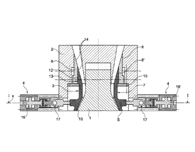
FIGS. lA and 1B show that the nozzle insert 3 has a
holding ring 6 axially supported at its lower end and a nozzle ring
7 set in the holding ring 6. The holding ring 6 is guided inside
the nozzle body 2 by a slide seat 8 and has a ridge 9 that can move
radially and projects into an installation space of the nozzle body
2 below the slide seat 8. The nozzle ring 7 is supported axially
inside or outside the holding ring 6 and is guided in the holding
ring 6 by a slide seat 8'. The nozzle ring 7 has a radially
movable nozzle ring section below the slide seat 8'. "Radially
movable" means that there is an open space between the side surface
of the holding ring 6 and the nozzle ring 7 and the wall surface of
the nozzle body 2 bordering the installation space, the open space
allowing radial movement of the holding ring 6 and the nozzle ring
7 below the respective slide seats 8, 8' thereof. Comparing FIGS.
LA and 1B, it is found that the first positioner 4 acts on the
nozzle ring 7 in a radial force-application direction x and that
the second positioner 5 acts radially on the ridge 9 of the holding
ring 6 in a force-application direction y that is different from
direction x.
The holding ring 6 is supported and can move radially on
a support a support ring 10 fixed in the installation space of the
nozzle body 2. The holding ring 6 has a cylindrical outer
peripheral surface that is machined as a seat surface fitting in a
cylindrical hole of the nozzle body 2. The cylindrical peripheral
outer surface of the holding ring and the respective cylindrical
hole of the nozzle body 2 are loosely fitted together. The
holding ring 6 is a metal sleeve and can have an annular section
between the slide seat 8 and a force application point for the
second positioner 5, the annular section allowing bending of the
holding ring 6 under the effect of a radial force produced by the
14
CA. 02860710 2014-08-27
second positioner 5. After releasing the radial force acting on
the holding ring 6, the ring bends back elastically at least
partially.
According to FIG. 1B, the second positioner 5 has at
least one actuator 11 that acts on the holding ring 6 by a
connection that transmits the radial pushing and pulling forces to
the holding ring 6.
The nozzle ring 7 has a collar 12 on its upper end, the
collar having a cylindrical sliding fit surface on its outer
surface, the surface being surrounded by the holding ring 6. The
sliding fit surface of the nozzle ring 7 and an associated
cylindrical inner surface of the holding ring 6 are fitted together
with play. The collar 12 of the nozzle ring 7 is supported at a
support and can move radially. In the illustrated embodiment, the
collar 12 of the nozzle ring 7 and the holding ring 6 are supported
on the same support, which is a support ring 10.
FIGS. 1A and 1B also show that the collar 12 of the
nozzle ring 7 and the section of the holding ring 6 surrounding the
collar 12 form a rigid middle piece 13 of the nozzle insert 3 and
that the second positioner 5 acts on the rigid middle piece 13 of
the nozzle insert 3 to effect a tilting displacement of the nozzle
insert 3.
The upper end surface of the holding ring 6 and the
nozzle ring 7 each have a beveled edge 14 that is adapted to the
passage shape of the annular gap, respectively.
In the illustrated embodiment shown in FIGS. 1A, 1B, the
nozzle ring section of the nozzle ring 7 adjacent the annular gap
at the nozzle outlet is an elastically deformable sleeve 15. The
first positioner 4 has two actuators 16, 16' that act, either
directly or via a coupling, radially on the elastically deformable
CA. 02860710 2014-08-27
sleeve 15 at force application points that are on the periphery of
the nozzle ring 7 angularly offset from one another by 180E, for
example. In the illustrated embodiments, the actuators 16, 16' of
the first positioner 4 are each connected to the nozzle ring 7 via
a joint or coupling 17 that compensates for equalizing motions in
the second axis y.
The connection between the actuators 16, 16' and the
elastically deformable sleeve 15 is designed such that radial
pushing and pulling forces can be transmitted to the sleeve 15.
The actuators 16, 16' are connected to a programmable controller.
The extrusion nozzle shown in FIGS. 2A, 28 is described
above. There are also ring seals 18, 18' between the components
that are movable relative to one another. A ring seal 18 is
provided between the nozzle body 2 and the holding ring 6 at the
slide seat 8. Also provided between the holding ring 6 and the
nozzle ring 7 is a ring seal 18' that is also in the slide seat 8'.
The seals 18, 18' can be 0-ring seals made of a temperature-
resistant material. Suitable ring seals can include metal-clad
soft material rings, corrugated metal rings with soft material
layering, grooved-profile ring seals and elastomeric ring seals
made of temperature-resistant polymers, for example. Also included
here are metal packing and carbon packing as ring seals 18, 18'.
In particular, the ring seals can also be tubular seals that
laterally support the holding ring 6 and/or the nozzle ring 7 near
the loose fit, thereby having a low-wear effect.
The extrusion nozzle, which is shown in FIGS. 14A and 14B
in half-section each, is of the design described with reference to
FIGS. LA and 1B. In the embodiment of FIG. 14A and 14B, the
holding ring 6 has a cylindrical peripheral outer surface, the
surface being machined as a seating surface and extending into an
16
Mk 02860710 2014-08-27
intermediate sleeve 31 in the nozzle body 2. The intermediate
sleeve 31 is supported axially in the nozzle body and guided inside
the nozzle body 2 by a slide seat. A purposeful loose fit is
provided between the peripheral surface of the intermediate sleeve
31 and a cylindrical hole of the nozzle body 2. The flexibility
and sealing function can be further improved by the intermediate
sleeve 31.
In the illustrated embodiments of FIGS. 3 to 7, at least
one actuator 16 is provided for displacing and/or deforming the
elastically deformable sleeve 15, the actuator acting on an outer
side surface of the sleeve 15 via a coupling formation 19, 19'.
The sleeve is usually made of metal and is thin-walled. Other
sleeve materials, such as temperature-resistant plastic and
composite materials, can also be used. A preferred embodiment of
the sleeve 15 is one that can be deformed both by radial pressure
and radial tension forces. During extrusion of the preforms, the
cross-sectional shape of the sleeve 15 is changed so as to affect
the shape of the annular gap s.
In the illustrated embodiment of FIG. 3, when an
adjusting motion is made, each of the coupling formations 19 acts
on one side on an outer side surface of a respective sleeve 15 that
is supported at a plurality of brace formations 20 around its
periphery. The number and position of the brace formations 20
affects the cross section of the sleeve 15 by adjusting by elastic
deformation when the coupling formation 19 acting on one side is
actuated. In the illustrated embodiment, there are three brace
formations 20 provided that are equidistant to one another at the
periphery of the sleeve 15, one of the brace formations 20 being
positioned offset by 180E relative to the force application point
of the coupling formation 19.
17
CA 02860710 2014-08-27
In the illustrated embodiment of FIG. 4, the coupling
formations 19, 19' act in pairs on the sleeve 15 and are
kinematically coupled. The coupling formations 19, 19', each of
which is associated with a respective sleeve 15, execute opposing
pincer movements when the actuator 16 makes an adjusting motion.
The actuator 16 is a pneumatic, hydraulic or electromagnetic unit
for generating a linear motion of a sliding element. The sliding
element cooperates with a linearly moving positioning element that
executes an opposite movement derived from the linear motion. In
addition, the sleeve 15 can be supported at brace formations 20
according to FIG. 4. It is preferable for four brace formations 20
to be provided directed at an angle of +/- 45E relative to the
deformation axis. The deformation axis is determined by the force
application points of the coupling formations 19, 19'.
Independent base adjustments can be made in arrangements
made up of a plurality of extrusion nozzles, these adjustments
involving the predeformation of the sleeves 15 of the extrusion
nozzles and/or correction of the position of the sleeves 15 and/or
the displacement of the nozzle insert 3 and the mandrel 1 of the
extrusion nozzles relative to one another. To modify the base
adjustment of the extrusion nozzles, individual respective
independently actuatable positioning elements 21, 21' are provided.
According to FIG. 4, positioning elements 21 are provided on the
coupling formations 19, 19' that act radially on the outer surface
of the respective sleeves 15. By actuating this positioning
element 21, the respective sleeve 15 associated with the
positioning element 21 can be deformed and the position thereof can
be corrected. Also provided are positioning elements 21' that act
on the nozzle insert 3 of the extrusion nozzles and that enable a
position correction of the nozzle insert 3 relative to the mandrel
18
CA 02860710 2014-08-27
1 of the extrusion nozzle. The change in a base adjustment at the
extrusion nozzles is advantageous since in the manufacture of small
blow-molded hollow members a small difference in the radial nozzle
gap area from one extrusion nozzle to the next extrusion nozzle
results in big differences in wall thickness of the preforms.
Therefore, it is important that every coupling formation 19, 19'
that acts on the sleeve 15 has a respective positioning element 21
to compensate for manufacturing tolerances. Also, the rheological
behavior of the plastic melt, manufacturing tolerances in the flow
passages of the extrusion nozzles, and temperature differences can
result in deviations in the tubular shape of the preforms exiting
the extrusion nozzles and the radial wall thickness distribution of
the individual preforms exiting the various extrusion nozzles. To
correct these effects, it can be useful if the base shape of the
sleeve 15 and the position thereof can be corrected at each sleeve
15 by the various positioning elements 21. The same applies to a
correction of the position between the nozzle insert 3 and the
mandrel 1 using the positioning elements 21'.
Also, in the illustrated embodiments of FIG. 5 and 6 the
coupling formations 19, 19' act in paired fashion on sleeves 15 and
exert pressure on both sides of the respective sleeve 15 during an
adjustment. The coupling formations 19, 19' of each pair are
kinematically coupled and carry out opposing pincer movements when
their actuator makes an adjusting motion. According to FIG. 5, the
actuator 16 is a spindle drive and has a rotatably mounted output
spindle with right-hand and left-hand threaded sections 22, 22' so
one element of the coupling pair associated with each sleeve 15 is
connected to a right-hand threaded section 22 and the other element
of the pair is connected to the left-hand threaded section 22'.
19
CA 02860710 2014-08-27
In the illustrated embodiment of FIG. 6, the actuator 16,
which is also a spindle drive, has two kinematically coupled output
spindles that rotate in opposite directions, one coupling formation
19 of the couplings associated with the respective sleeves being
connected to a first output spindle and the other coupling of the
pair being connected to the second output spindle.
The coupling formations 19, 19' can also be slides that
each have a cam surface 23 that cooperates with a surface of the
respective sleeve 15. Such a mechanical solution is shown in FIG.
7. The cam surfaces 23 consist of a chamfered end of the slide.
The slides exert pressure on both sides of the respective sleeve 15
when an adjusting motion is made and deform the sleeve
elliptically. The slides, which are connected at the back to a
common cross member 24, are passed between pressure plates whose
position is adjustable by positioning means. By adjusting the
pressure plates, base adjustments can be made at the extrusion
nozzles individually. The positions of the sleeves 15 can be
corrected by these base adjustments. Also, individual
predeformations of the sleeve 15 are possible.
The connection region 25 between the coupling formation
19, which is a slide, and a sleeve 15 can be configured such that
pulling forces are transmitted to surfaces of the sleeve 15 when
the coupling formations 19 make adjusting motions and the sleeves
15 are deformed elliptically by pulling forces acting on both
sides. In this case, the slides act on control surfaces connected
to the sleeves 15. The connection region 25 between the coupling
formations 19 and the sleeves 15 can also be designed such that a
pulling force or a pushing force is transmitted to the sleeves
during an adjusting motion of the coupling formations 19 as a
function of the adjustment path. A corresponding connection
CA 02860710 2014-08-27
element is shown in FIG. 8. The coupling formation 19 extends into
the connection element, which is connected to the sleeve 15 and has
a cam surface 23 for transmitting radial pushing forces and a cam
surface 23' for transmitting radial pulling forces.
In the section of FIG. 9, an example of a nozzle gap
geometry is shown whose geometry is adjustable between the mandrel
1 and the nozzle insert 3. The coupling formations 19, 19' extend
into connection elements that are removably connected to the sleeve
15 through positive locking elements 26. The elastically
deformable sleeve 15 is exchangeable without having to remove the
connection elements and associated coupling formations 19.
Considering the illustrated embodiments shown in FIG. 3
to 9, it remains to be noted that the second positioner 5 can also
comprise a plurality of couplings that synchronously transfer
adjusting motion of an actuator to the actuating portion 9 of the
holding ring 6 of a plurality of extrusion nozzles disposed next to
one another.
According to the embodiments of the extrusion nozzle
according to the invention shown in FIGS. 10A and 10B and FIGS. 15A
and 15B, the nozzle ring 7 has a section adjacent the annular gap s
at the nozzle outlet, the section being designed to be rigid. The
first positioner 4 has at least one actuator 16 that acts on the
rigid nozzle ring section, whereas in each of the illustrated
embodiments, two actuators 16, 16' are actually provided. By
actuating both the actuators 16, 16' of the first positioner 4 and
the actuator 11 of the second positioner 5, the rigid nozzle ring
section can be shifted in two axial directions x, y relative to the
mandrel 1 in order to affect the nozzle gap geometry. In FIGS. 10A
and 10B, the actuator 11 of the second positioner 5, as in all
embodiments described up until now, acts radially on the actuating
21
CA 02860710 2014-08-27
portion 9 of the holding ring 6, the actuating portion projecting
into an installation space of the nozzle body 2 below the slide
seat 8 of the holding ring, and being movable radially. According
to the FIGS. 15A and 15B, the actuator 11 of the second positioner
is associated with the nozzle ring 7 and also acts radially on
the nozzle ring 7 as do the actuators 16, 16> of the first
positioner.
In the illustrated embodiments shown in FIGS. 11, 12, 13A
and 13B, the second positioner 5 is associated with the holding
ring 6 and acts radially on the actuating portion 9 of the holding
ring 6. According to FIG. 11, the actuating portion 9 of the
holding ring 6 and the radially movable nozzle ring section of the
nozzle ring 7 are kinematically coupled. The kinematic coupling is
achieved by a slotted guide 27. In the illustrated embodiment,
this guide has at least one radial projection 29 that extends into
a guide slot and is directed perpendicular to the direction of
force application of the second positioner 5 that acts on the
holding ring 6 and can be a pin, for example. The guide slot is
formed in the holding ring 6 and extends vertically downward. The
guide slot can be incorporated into the wall of the holding ring 6.
In the illustrated embodiment, the slot is a forked guide piece
fastened to the holding ring 6. The projection 29 is connected to
the nozzle ring 7 and extends radially. The kinematic coupling
between the nozzle ring 7 and the holding ring 6 causes a tilting
displacement of the holding ring 6 to result in a defined,
verifiable and reproducible change in the position of the nozzle
ring 7. It is useful to provide the nozzle ring with a sensor (not
shown) that records the movements of the nozzle ring 7 along the
axes defined by the direction of force application of the first
positioner 4 and the direction of force application of the second
22
CA 02860710,2014-08-27
positioner 5. The measured values from the sensor can then be used
to control the position of the nozzle insert 3.
In an illustrated embodiment shown in FIG. 13A and 13B,
the actuating portion 9 of the holding ring 6 and the radially
movable nozzle ring section of the nozzle ring 7 are also
kinematically coupled. The kinematic coupling is achieved by a
slotted guide that has two radial projections 29 that extend into
respective guide slots 28. The radial projections 29 extend
perpendicular to the direction of force application of the second
positioner that acts on the holding ring 6 and are guide pins. The
second positioner 5 has a connector fork 32 connected to the
slotted guide 27 and transmitting the adjusting motion of the
second positioner to the holding ring 6. The fork is pivoted on
the actuator 11 of the second positioner 5. The direction of force
application of the second positioner 5 is radially directed to the
ridge 9 of the holding ring 6, the force being introduced at two
force application points 33 opposite one another. This results in
the deformation force acting locally on the holding ring 6 being
lower, and allows the ring section where the force is introduced to
be designed with a lower degree of rigidity.
In the illustrated embodiment of the extrusion nozzle
according to the invention as shown in FIG. 12, the holding ring 6
extends to the bottom end of the nozzle insert 3 and is carried on
a support while being radially movable, the support being at the
bottom end of the nozzle body 2 and being a support ring 10, for
example. The second positioner 5 acting on the holding ring 6 and
the first positioner 4 acting on the nozzle ring 7 are at about the
same level. The nozzle ring 7 is attached to the holding ring 6
below the slide seat 8' of the nozzle ring by a removable positive-
lock connection 30 that permits relative radial movements. In
23
CA 02860710,2014-08-27
particular, the positive-lock connection 30 can be a bayonet joint.
An advantage of this support is that the nozzle ring 7 can be
rapidly replaced using the bayonet joint.
In all embodiments, the actuators 16, 16' of the first
positioner 4 and the actuator 11 of the second positioner 5 are
supported on the nozzle body 2. It is also an aspect of the
invention that the adjusting motions of the first positioner 4 and
the second positioner 5 are coupled. In particular, a coupling can
be provided in such a fashion that only the actuator/actuators of
one of the two positioners 4, 5 is/are supported on the nozzle body
and the actuator/actuators of the other positioner is/are
cooperatively moved and supported thereby.
Embodiments of the extrusion nozzle according to the
invention were illustrated with the aid of the illustrated
embodiments in order to affect the radial nozzle gap shape at the
nozzle outlet by displacing a nozzle insert made of a plurality of
parts. The features of the embodiment shown can be combined in any
manner.
List of references
1 Mandrel 13 Rigid middle piece
2 Nozzle body 14 Chamfer
3 Nozzle insert 15 Elastically deformable
4, 5 Positioners sleeve
6 Holding ring 16, 16' actuators
7 Nozzle ring 17 Coupling
8, 8' slide seat 18, 18' Ring seals
9 Actuating portion 19, 19' Coupling
Support ring 20 brace formation
11 actuator 21, 21' Positioning elements
12 Collar 22, 22' Thread sections
24
CA 028607102014-08-27
23, 23' Cam surfaces 30 Positive-lock connection
24 Traverse 31 Intermediate sleeve
25 Connection region 32 Connector fork
26 Positive locking elements 33 Force application point
27 Slotted guide s Annular gap
28 Guide slot x, y Axis directions
29 Radial projection