Note: Descriptions are shown in the official language in which they were submitted.
CA 02860777 2014-07-07
WO 2013/122561 PCT/US2012/024843
- 1 -
ATTACHMENT OF WEAR. MEMBER TO LIP OF EXCAVATION
IMPLEMENT
TECHNICAL FIELD
This disclosure relates generally to equipment utilized
and operations performed in conjunction with excavation
implements and, in one example described below, more
particularly provides for improved attachment of a wear
member to a lip of an excavation implement.
BACKGROUND
A lip of an excavation implement can become damaged or
worn, due to engagement with material being excavated. It is
important to protect the lip from wear, and so it is common
practice to attach wear members to a forward edge of the
lip. It will be appreciated the improvements are continually
needed in the art of attaching wear members to lips of
excavation implements.
CA 060777 20107-137
WO 2013/122561 PCT/US2012/024843
- 2 -
SUMMARY
In this disclosure, systems and methods are provided
which bring improvements to the art of attaching wear
members to lips of excavation implements. One example is
described below in which a biasing device maintains a wear
member resiliently against a lip. Another example is
described below in which a fastener is threaded through a
locking device to compress the biasing device.
An attachment system for use with an excavation
implement is described below. In one example, the system can
include a retainer which secures a wear member to a lip of
the excavation implement, with the retainer being fixedly
attached to the lip. A biasing device is retained within the
retainer. The biasing device biases the wear member toward
the lip.
A method of attaching a wear member to a lip of an
excavation implement is also provided to the art. The method
can include installing a biasing device in a retainer
fixedly secured to the lip, and then positioning the wear
member on the lip.
Another attachment system is described below. In an
example, a retainer which secures a wear member to a lip of
the excavation implement is fixedly attached to the lip. A
biasing device biases the wear member toward the lip. A
locking device extends through the wear member. The biasing
device is compressed between the retainer and the locking
device.
Another method of attaching a wear member to a lip of
an excavation implement can include the steps of:
positioning the wear member on the lip, then extending a
locking device from the wear member, and then compressing a
CA 060777 20107-137
WO 2013/122561 PCT/US2012/024843
- 3 -
biasing device between the locking device and a retainer
fixedly secured to the lip.
These and other features, advantages and benefits will
become apparent to one of ordinary skill in the art upon
careful consideration of the detailed description of
representative embodiments of the disclosure hereinbelow and
the accompanying drawings, in which similar elements are
indicated in the various figures using the same reference
numbers.
BRIEF DESCRIPTION OF THE DRAWINGS
FIG. 1 is a representative oblique view of an
excavation implement which can embody principles of this
disclosure.
FIGS. 2-10 are representative views of an attachment
system and steps in a method of attaching a wear member to a
lip of the excavation implement, which attachment system and
method can embody principles of this disclosure.
FIG. 11 is a representative cross-sectional view of
another example of the attachment system.
DETAILED DESCRIPTION
Representatively illustrated in FIG. 1 is an excavation
implement 10 and associated method which can embody
principles of this disclosure. However, it should be clearly
understood that the implement 10 and method are merely one
example of an application of the principles of this
disclosure in practice, and a wide variety of other examples
are possible. Therefore, the scope of this disclosure is not
CA 060777 20107-137
WO 2013/122561 PCT/US2012/024843
- 4 -
limited at all to the details of the implement 10 and method
described herein and/or depicted in the drawings.
In the example of FIG. 1, the implement 10 is of the
type known as a "dipper" or "bucket" of a cable shovel, but
it should be clearly understood that the principles of this
disclosure can be utilized with other types of excavation
implements. Indeed, the principles of this disclosure could
be used to improve the attachment of wear members to any
type of excavation implements.
In the illustration of FIG. 1, the implement 10 is
rotated so that an earth-engaging side of the implement is
clearly visible. From this perspective, it may be seen that
multiple teeth 12 are mounted on the implement 10 for
piercing the earth.
These teeth 12 are typically rapidly worn down or
otherwise damaged during use of the implement 10, and so
replacement of the teeth should be conveniently,
economically, rapidly and safely accomplished. These
objectives are obtained by use of specially configured
adapters 14 which releasably secure the teeth 12 to a
forward edge of a lip 16 of the implement 10.
The adaptors 14 are examples of wear members that
protect the earth-engaging lip 16 of the implement 10. Other
examples of wear members include shrouds 18, which wrap
around the forward edge of the lip 16 between the adaptors
14. In yet another example, the teeth 12 can be attached to
the lip 16, without use of the separate adaptors 14, in
which case the teeth can themselves serve as wear members
for protection of the lip. Any type of wear member can be
used, in keeping with the scope of this disclosure.
Referring additionally now to FIGS. 2 & 3, an
attachment system 20 and associated method are
CA 060777 20107-137
WO 2013/122561
PCT/US2012/024843
- 5 -
representatively illustrated for attaching a wear member to
a lip of an excavation implement. The system 20 is described
below as being used for attaching a wear member 22 (not
shown in FIGS. 2 & 3, see FIGS. 6-11) to the implement 10,
but it should be clearly understood that the system can be
used for attaching other types of wear members to lips of
other types of excavation implements, and so the scope of
this disclosure is not limited at all to the details of the
system as depicted in the drawings and described below.
In FIGS. 2 & 3, an initial step of fixedly securing a
retainer 24 to the lip 16 is depicted. In this example, the
retainer 24 is secured to an upper side 26 of the lip 16,
spaced away from a forward earth-engaging edge 28 of the
lip.
In other examples, more than one retainer 24 could be
used, the retainer could be secured to a lower or vertical
side of the lip 16, the retainer could be secured at or to
the forward edge 28, etc. Thus, the details of the retainer
24 and its positioning on the lip 16 can be varied, in
keeping with the scope of this disclosure.
The retainer 24 may be secured to the lip 16 by
welding, by use of fasteners (such as, bolts, rivets, etc.),
or by any other suitable means. Preferably, the retainer 24
is fixedly secured to the lip 16, so that it can resist
forces applied during excavation operations. A technique for
attaching the retainer 24 to the lip 16 should be selected
based on expected excavation conditions for a certain
application.
Referring additionally now to FIGS. 4 & 5, a biasing
device 30 is installed in the retainer 24. In this example,
the biasing device 30 is retained within a recess 32 formed
in the retainer 24. In this manner, the biasing device 30 is
CA 060777 20107-137
WO 2013/122561 PCT/US2012/024843
- 6 -
protected within the retainer 24 during excavation
operations. However, in other examples, the biasing device
30 may not be retained within the retainer 24.
The biasing device 30 in this example includes a
resilient elastomer (such as rubber, etc.) member 34 and a
plate 36 for compressing the resilient member against the
retainer 24. This compression of the resilient member 34
applies a biasing force to retain the wear member 22 against
the forward edge 28 of the lip 16, as described more fully
below.
Referring additionally now to FIG. 6, the wear member
22 is representatively illustrated as being installed onto
the lip 16. In this example, the wear member 22 comprises an
earth-engaging tooth, but in other examples, the wear member
could comprise an adaptor, a shroud, or any other type of
wear member.
It is desired that, after the wear member 22 is
positioned on the lip 16, the wear member will be
continually biased into contact with the forward edge 28 of
the lip, in order to mitigate wear between the wear member
and the lip during excavation operations. For this purpose,
the biasing device 30 is used to bias the wear member 22 in
a direction 38 toward the lip 16, as described more fully
below.
In this example, it is desired to maintain contact
between the forward edge 28 and a generally C-shaped recess
40 in the wear member 22. However, in other examples, the
forward edge 28 and recess 40 may be otherwise shaped,
engagement may be maintained between other surfaces on the
wear member 22 and the lip 16, etc.
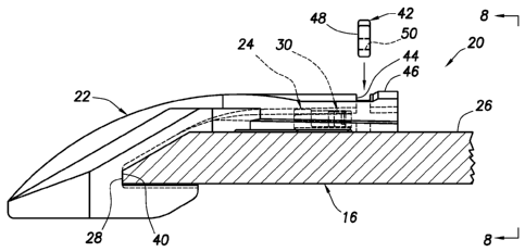
Referring additionally now to FIGS. 7 & 8, a locking
device 42 is being installed through an opening 44 formed
CA 060777 20107-137
WO 2013/122561 PCT/US2012/024843
- 7 -
through an upper wall 46 of the wear member 22. In this
example, the locking device 42 comprises a flat plate 48
having a threaded opening 50 extending through the plate.
However, other configurations may be used for the locking
device 42, in keeping with the scope of this disclosure.
Referring additionally now to FIG. 9, the system 20 is
depicted after the locking device 42 has been inserted in
the opening 44, and a fastener 52 is being installed. In
this example, the fastener 52 is threaded through the
opening 50 to compress the biasing device 30. However, in
other examples the biasing device 30 could be compressed by
other means, in keeping with the scope of this disclosure.
Referring additionally now to FIG. 10, the system 20 is
depicted after the fastener 52 has been threaded
sufficiently far through the locking device 42 to contact
the plate 36 and compress the resilient member 34. This
compression of the biasing device 30 applies a rearward-
directed biasing force to the fastener 52 and via the
locking device 42 to the wear member 22. Thus, the wear
member 22 is biased toward the lip 16 by the biasing device
30.
Note that, even if the fastener 52 should inadvertently
be lost during an excavating operation, the locking device
42 can still abut the retainer 24 and prevent removal of the
wear member 22 from the lip 16. Thus, the wear member 22 can
remain on the lip 16 until the fastener 52 is replaced.
However, it is anticipated that the residual biasing force
exerted by the biasing device 30 on the fastener 52 will
prevent the fastener from unthreading from the locking
device 42.
Note that the fastener 52 is compressed in the area
between the locking device 42 and the biasing device 30. The
CA 060777 20107-137
WO 2013/122561 PCT/US2012/024843
- 8 -
biasing device 30 is compressed between the locking device
42 and the retainer 24, or more precisely, between the
fastener 52 and the retainer 24.
In FIG. 11, another example of the system 20 is
representatively illustrated. In this example, the resilient
member 34 of the biasing device 30 is in the form of a
spiral compression spring. Other types of springs, and other
types of resilient members may be used in the biasing device
30 in keeping with the principles of this disclosure.
Furthermore, it is not necessary for the biasing device
30 to include the resilient member 34, since a biasing force
can be exerted using other means. For example, a pressurized
gas chamber, a shape memory alloy, or any other element
could exert the biasing force in the biasing device 30.
It may now be fully appreciated that the above
disclosure provides significant advancements to the art of
attaching wear members to lips of excavator implements. In
the system 20, the wear member 22 can be conveniently
attached to the lip 16 of the implement 10 using the biasing
device 30 which is retained within the retainer 24. The
fastener 52 threaded through the locking device 42, in
cooperation with the retainer 24 and biasing device 30,
resiliently retains the wear member 22 on the lip 16, with
the recess 40 of the wear member maintained in contact with
the forward edge 28 of the lip.
An attachment system 20 for use with an excavation
implement 10 is described above. In one example, the system
20 comprises a retainer 24 which secures a wear member 22 to
a lip 16 of the excavation implement 10. The retainer 24 is
fixedly attached to the lip 16. A biasing device 30 is
retained within the retainer 24. The biasing device 30
biases the wear member 22 toward the lip 16.
CA 060777 20107-137
WO 2013/122561
PCT/US2012/024843
- 9 -
The biasing device 30 may be compressed in response to
installation of a fastener 52 through a locking device 42
which extends inwardly from the wear member 22. The fastener
52 may be threaded through the locking device 42.
The fastener 52 may be compressed between the locking
device 42 and the biasing device 30. The biasing device 30
may be compressed between the locking device 42 and the
retainer 24.
The fastener 52 may be compressed between the retainer
24 and the locking device 42. The biasing device 30 may be
compressed between the retainer 24 and a locking device 42
which extends from the wear member 22.
The system 20 can include a locking device 42 which
extends from the wear member 22 and abuts the retainer 24,
thereby preventing removal of the wear member 22 from the
lip 16.
A method of attaching a wear member 22 to a lip 16 of
an excavation implement 10 is also described above. In one
example, the method can include: installing a biasing device
30 in a retainer 24 fixedly secured to the lip 16; and then
positioning the wear member 22 on the lip 16.
The method can include extending a locking device 42
from the wear member 22, after positioning the wear member
22 on the lip 16. The locking device 42 may prevent removal
of the wear member 22 from the lip 16 by abutting the
retainer 24.
The method can also include compressing the biasing
device 30, thereby biasing the wear member 22 toward the lip
16. The compressing can comprise compressing the biasing
device 30 between the retainer 24 and the locking device 42,
CA 02860777 2014-07-07
WO 2013/122561 PCT/US2012/024843
- 10 -
and/or compressing a fastener 52 between the locking device
42 and the biasing device 30.
Compressing the biasing device 30 can comprise
installing the fastener 52, thereby securing the locking
device 42. Installing the fastener 52 can comprise threading
the fastener 52 through the locking device 42, and/or
compressing the fastener 52.
Another attachment system 20 for use with an excavation
implement 10 can include a retainer 24 which secures a wear
member 22 to a lip 16 of the excavation implement 10, the
retainer 24 being fixedly attached to the lip 16; a biasing
device 30 which biases the wear member 22 toward the lip 16;
and a locking device 42 which extends from the wear member
22. The biasing device 30 is compressed between the retainer
24 and the locking device 42.
The biasing device 30 can be retained within the
retainer 24. The locking device 42 can abut the retainer 24
and thereby prevent removal of the wear member 22 from the
lip 16.
The biasing device 30 can be compressed in response to
installation of a fastener 52 through the locking device 42.
The fastener 52 may be threaded through the locking device
42.
Another method of attaching a wear member 22 to a lip
16 of an excavation implement 10 can comprise: positioning
the wear member 22 on the lip 16; then extending a locking
device 42 from the wear member 22; and then compressing a
biasing device 30 between the locking device 42 and a
retainer 24 fixedly secured to the lip 16.
The method can include installing the biasing device 30
in the retainer 24. Installing the biasing device 30 may be
CA 060777 20107-137
WO 2013/122561 PCT/US2012/024843
- 11 -
performed prior to positioning the wear member 22 on the lip
16.
Although various examples have been described above,
with each example having certain features, it should be
understood that it is not necessary for a particular feature
of one example to be used exclusively with that example.
Instead, any of the features described above and/or depicted
in the drawings can be combined with any of the examples, in
addition to or in substitution for any of the other features
of those examples. One example's features are not mutually
exclusive to another example's features. Instead, the scope
of this disclosure encompasses any combination of any of the
features.
Although each example described above includes a
certain combination of features, it should be understood
that it is not necessary for all features of an example to
be used. Instead, any of the features described above can be
used, without any other particular feature or features also
being used.
It should be understood that the various embodiments
described herein may be utilized in various orientations,
such as inclined, inverted, horizontal, vertical, etc., and
in various configurations, without departing from the
principles of this disclosure. The embodiments are described
merely as examples of useful applications of the principles
of the disclosure, which is not limited to any specific
details of these embodiments.
In the above description of the representative
examples, directional terms (such as "above," "below,"
"upper," "lower," etc.) are used for convenience in
referring to the accompanying drawings. However, it should
ak 02860777 2015-11-16
- 12 -
be clearly understood that the scope of this disclosure
is not limited to any particular directions described
herein.
The terms "including," "includes," "comprising,"
"comprises," and similar terms are used in a non-limiting
sense in this specification. For example, if a system,
method, apparatus, device, etc., is described as
"including" a certain feature or element, the system,
method, apparatus, device, etc., can include that feature
or element, and can also include other features or
elements. Similarly, the term "comprises" is considered
to mean "comprises, but is not limited to."
Of course, a person skilled in the art would, upon a
careful consideration of the above description of
representative embodiments of the disclosure, readily
appreciate that many modifications, additions,
substitutions, deletions, and other changes may be made
to the specific embodiments, and such changes are
contemplated by the principles of this disclosure. For
example, structures disclosed as being separately formed
can, in other examples, be integrally formed and vice
versa. Accordingly, the scope of the claims should not be
limited by the preferred embodiments set forth in the
examples, but should be given the broadest interpretation
consistent with the description as a whole.