Note: Descriptions are shown in the official language in which they were submitted.
CA 02861671 2014-09-02
COMBINATION WELDING METHOD OF SIMULTANEOUSLY
PERFORMING TUNGSTEN ARC WELDING AND SUBMERGED ARC
WELDING
CROSS-REFERENCE TO RELATED APPLICATION
This application claims the benefit of Korean Patent Application No. 10-
2014-0041892, filedon April 8,2014.
BACKGROUND OF THE INVENTION
1. Field of the Invention
The present invention relates toa combination welding method of
simultaneously welding an inside surface and an outside surface of a steel
pipe
by leading with tungsten arc welding to the inside surface of the steel pipe
and
followingwith submerged arc welding to the outside surface of the steel pipe
by
keeping a predetermined separation distance between an inside welding point
and an outside weldingpoint, in a combination method for manufacturing steel
pipes.
2. Description of the Related Art
Of the methods for manufacturing steel pipes, a welding method having a
good low-temperature impact value is a seamless steel pipe method. However,
the seamless steel pipe method is high in supply price and requires a
relatively
long period for supply, compared with other welding methods. In a shipbuilding
company which is a source of demand, the just-in-time supply of seamless steel
pipes is a very important factor in meeting the deadline in building a ship.
-1-
CA 02861671 2014-09-02
Electric resistance welding is a method of welding workpieces to be
welded by facing the workpieces against each other, generating resistance heat
by applying current and compressing the heat to produce a weld. Since this
electric resistance welding method produces the weld at a very fast speed, it
has the advantage of high productivity. Therefore, the electric resistance
welding method is mostly usedfor tube milling of hot rolled coils.
However, metal flow occurs in the weld zone using the electric resistance
welding method. If the workpieces include a crack or coarse inclusion, a crack
occurs in the weld zone. As shown in Table 1, since the low-temperature impact
lo value is very low, the welded workpieces are not proper to be used as
steel pipe
for piping. However, if the steel pipe is manufactured using the seamless
steel
pipe method, since the price is higher by about twice or more than the steel
pipe
using the electric resistance welding method, there have been difficulties
inpriceto apply the seamless steel pipe method to the steel pipe to the field.
Table 1
Electric Submerged arc Remarks
resistance welding (SAW)
welding (ERW)
Mechanical Low-temperature -40 C Impossible 48 Jule Extent
of
properties impact value -60 C Impact warranty 27 Jule
excellence in
(27Jule at 0 C) mechanical
Tensile strength Based on API 5L Based on API 5L properties:
X-52:510MPa X-52:530MPa
Seamless>SAW>E
RW
Table 1 above provides the mechanical properties of the weld zone
according to the welding methods.
-2-
CA 02861671 2014-09-02
The submerged arc welding is a method for welding two or more
workpieces to be joined together by using heat obtained by generating an arc
between a wire and a base material under granular flux. The welding is
performed by continuously feeding the electric current charged wire into the
granular flux pre-layered on the base material. The arc is not shown to the
outside since it is covered by the flux. The flux protects the arc by blocking
the
atmosphere when refining the welded metal. The flux contributes to the
formation of the welding bead or slag.
The submerged arc welding method is used a lot as a highly efficient
io joining technique of thick plate steel for pipes since the size of the
welding rod
and the current to be used are great, the depth of weld penetration is deep.
Due to these good welding characteristics, the submerged acc welding method
is considered as a representative of a highly efficient welding method having
the
mechanical properties that the low-temperature impact value is excellent and
is the tensile strength is not much different from those of the seamless
steel pipe
methodas shown in Table 1.
Since the steel pipe using the submerged arc welding method has no
difference in the mechanical properties from the seamless steel pipe, the
applicant of the present application had registered a combination welding
20 method of performing electric resistance welding and submerged arc welding
(Korean Patent Registration Publication No. 10-1191711 published on October
10, 2012) to meet the request for prompt period of supply/delivery.
According to the conventional combination welding method using the
electric resistance welding and the submerged arc welding (hereinafter,
referred
- 3 -
CA 02861671 2014-09-02
to as the 'prior aft), it is possible to manufacture steel pipes at a fast
speed,
compared with the use of the previous submerged arc welding method only. It
is also possible to manufacture steel pipes having better mechanical
properties,
compared with the use of the previous electric resistance welding method.
Further, the manufacturing processes are shortened to reduce the process
equipment and the manufacturing processes are simplified to reduce the
production cost.
However, in the welding method according to the prior art as shown in
FIG. 1, after tack welding is performed using the electric resistance welding
io method, since the inside surface of a steel pipe is first welded by the
submerged arc welding method and then the outside surface thereof is welded,
a fusion area of a weld zonesolidifies and contracts after welding the inside
surface of the steel pipe, occurring bending toward the inside of the steel
pipe,
as shown in FIG. 2. The reason why the bending phenomenon occurs is
is because the fusion area solidifies at the temperature of 1500 C or
higher and
steel contracts as it passes an Al transformation pointof steel (723 C).
When the outside surface of the steel pipe is welded using the
submerged arc welding method after the first welding of the inside surface of
the steel pipe is performed, since the fusion area of the weld zonesolidifies
and
20 contracts after the inside welding, bending occurs toward the outside of
the
steel pipe. However, even though the outside surface of the steel pipe is
welded, there occurs no bending sufficient to correct the bending which
occurred upon the first welding to the inside surface of the steel pipe to the
original state.
-4-
CA 02861671 2014-09-02
Even if the welding method is to be changed so as to simultaneously
perform the inside welding and the outside welding of the steel pipe in order
tosolve the aforementioned problem(s), since the submerged arc welding
method needs the flux and the supplied flux drops downwardly in any one place
of the inside surface and outside surface, it is impossible to perform normal
welding.
Tungsten arc welding is a method of welding a base material by using
heat obtained by generating an arc between a tungsten electrode and the base
material in an inert gas atmosphere, with no flux. The tungsten arc welding
method is slower in welding speed, compared with the submerged arc welding
method. However, since the arc is stable and the quality of the weld zone is
excellent, the tungsten arc welding method is used to weld the materials
sensitive to oxidation or nitration. The advantages of the tungsten arc
welding
method are that there is no need to remove slag after welding, no flux is
needed,
the deformation of the weld zone is small, and all-position welding is
possible.
When the tungsten arc welding method needing no flux, having high
quality weld zone and enabling all-position welding is applied to the inside
welding of the steel pipe and the submerged arc welding method is applied to
the outside welding of the steel pipe, it is possible to simultaneously
perform the
inside and outside welding of the steel pipe.
Prior Art Literature
Patent Documents
(Patent Document 0001) Korean Patent Registration Publication No. 10-
1191711 (October 10, 2012)
- 5 -
CA 02861671 2014-09-02
(Patent Document 0002) Korean Patent Laid-Open Publication No. 10-2009-
0130955 (December 28, 2009)
SUMMARY OF THE INVENTION
Therefore, it is an object of the present invention to solve the above
problems and to provide acombination welding method of simultaneously
performing tungsten arc welding and submerged arc welding, to prevent the
occurrence of excessive bending toward the inside of a steel pipe during the
processes of welding an inside surface and an outside surface of the steel
pipe,
m thereby shortening the welding time and straightening time and improving
welding productivity.
In accordance with an embodiment of the present invention, there is
provided a combination welding method comprising the steps of:
forming a steel sheet in the form of a steel pipe by using forming rollers;
performing electric resistance welding to ends to be joined together in the
roll-formed steel pipe;
performing tungsten arc welding to an inside surface of the ends of the
steel pipe; and
performing submerged arc welding to an outside surface of the ends of
the steel pipe,
wherein the inside surface of the ends of the steel pipe is welded by
leading with the tungsten arc welding and simultaneously the outside surface
of
the ends of the steel pipe is welded by following with the submerged arc
welding by keeping a separation distance of 100-150mm from a tungsten arc
weld zone, so that the outside welding can proceed before a fusion area goes
-6-
CA 02861671 2014-09-02
down below an Al transformation point after the inside welding and after
welding, bending of the steel pipe is controlled to shorten a straightening
time in
a post-process.
Preferably, the step of forming the steel pipe may follow the steps of:
cutting a raw material; feeding a coil of the raw material (uncoiling); and
leveling
thefed coil of the raw material.
Preferably, the combination welding method may further comprise: the
step of performing scaling to the inside surface of the steel pipe using a
buffing
device and forming a groove in the weld zone of the outside surface of the
steel
pipe between the step of performing the electric resistance welding and the
step
of performing the tungsten arc welding to the ends of the steel pipe formed by
the rollers.
Preferably, the separation distance between the tungsten arc weld zone
and the submerged arc weld zone may be increased if an outside temperature
is high and it may be decreased if the outside temperature is low.
Preferably, the step of performing the submerged arc welding to the
outside surface of the steel pipe may be followed with the steps of:
performing
heat-treatment to the welded steel pipe; straightening the heat-treated steel
pipe; performing a beveling process to the straightened steel pipe; and
performing a non-destructive test to the beveling processed steel pipe.
Preferably, the size of the steel pipe to which the combination welding
method applies may be 8-14 inches.
Preferably, the thickness of the steel pipe to which the combination
welding method applies may be 7.0-22.2mm and the length of the steel pipe
-7-
CA 02861671 2014-09-02
may be 12meters.
Preferably, the steel pipe may be manufactured by the combination
welding method.
BRIEF DESCRIPTION OF THE DRAWINGS
The above and other features and advantages of the present invention
will become more apparent to those of ordinary skill in the art by describing
in
detail preferred embodiments thereof with reference to the attached drawings
in
which:
FIG. 1 is a manufacturing process drawing applying the conventional
electric resistance welding and submerged arc welding methods;
FIG. 2 is an example view showing a bending defect of a steel pipe
which occurred by the manufacturing process of FIG. 1;
FIG. 3 is a schematic view of a combination welding method of
is simultaneously performing tungsten arc welding and submerged arc welding
according to the present invention;
FIG. 4 is a welding flow chart of the combination welding method
according to the present invention;
FIG. 5 is a schematic view showing the measurement of the straightness
of the steel pipe after welding; and
FIG. 6 is a cross-sectional view showing weld zones where the prior art
and the present invention are respectively applied.
- 8 -
CA 02861671 2014-09-02
DETAILED DESCRIPTION OF THE PREFERRED EMBODIMENT
The present invention will now be described more fully hereinafter with
reference to the accompanying drawings, in which a preferred embodiment of
the invention is shown so that those of ordinary skill in the art can easily
carry
out the present invention.
FIG. 1 is a manufacturing process drawing applying the conventional
electric resistance welding and submerged arc welding methods, FIG. 2 is an
example view showing a bending defect of a steel pipe which occurred by the
manufacturing process of FIG. 1, FIG. 3 is a schematic view of a combination
io welding method of simultaneously performing tungsten arc welding and
submerged arc welding according to the present invention, FIG. 4 is a welding
flow chart of the combination welding method according to the present
invention,
FIG. 5 is a schematic view showing the measurement of the straightness of the
steel pipe after welding, and FIG. 6 is a cross-sectional view comparatively
is showing weld zones where the prior art and the present invention are
respectively applied.
FIG. 1 shows the process of manufacturing a steel pipe, using the
conventional combination welding method of performing the electric resistance
welding and the submerged arc welding. First, a raw material coil is fed;
20 second, the raw material coil is leveled; third, the leveled raw
material is formed
in the form of a steel pipe, using forming rollers; fourth, after both ends of
the
steel pipe to be joined together are placed to face each other, the current is
applied to generate resistance heat and the resistance heat is compressed to
produce a weld. The fast process of the electric resistance welding is used
until
- 9 -
CA 02861671 2014-09-02
the fourth step. After that, the submerged arc welding method is used to
produce the weld. After the steel pipe welded using the electric resistance
welding method is fit-up, the following processes are performed: fifth, an
inside
welding process of the steel pipe, sixth, a long seam milling process to an
outside weld zone of the steel pipe, and seventh, an outside welding process
of
the steel pipe.
The aforementioned prior art has the advantagesin that: it is possible to
fast manufacture the steel pipe, compared with the previous single submerged
arc welding method only, it is possible to manufacture the steel pipe having
11:1 good mechanical properties, compared with the previous electric
resistance
welding method, the manufacturing process is shortened to reduce the process
equipment, and the manufacturing process is simplified to reduce the
production cost.
However, in the prior art, when the inside surface of the steel pipe is
welded using the submerged arc welding method after tack welding is
performed using the electric resistance welding method, a fusion area of the
weld zone solidifies and contracts after the inside welding, resulting in a
bending toward the inside of the steel pipe, as shown in FIG. 2. The reason
why this phenomenon occurs is because the fusion area solidifies at a
temperature of 1500 C or higher and steel contractspassing an Al
transformation point (723 C) of steel.
When the outside surface of the steel pipe is welded using the
submerged arc welding method, the fusion area of the weld zone solidifies and
contracts after the inside welding, resulting in bending toward the outside of
the
-
CA 02861671 2014-09-02
steel pipe. However, in the combination welding method of the prior art, even
though the outside welding is performed, there occurs little bending which is
sufficient to correct the extent of the bending which occurred upon the inside
welding to the original state.
Even if the welding method is changed so as tosimultaneously perform
the inside welding and the outside welding of the steel pipe in order to solve
the
aforementioned problem, since the submerged arc welding method needs flux,
the flux drops downwardly at any one place of the inside surface and the
outside surface of the steel pipe, making it impossible to simultaneously
perform
io the inside welding and the outside welding of the steel pipe.
To solve the problems of the prior art, the present invention provides a
combination welding method of simultaneously performing tungsten arc welding
and submerged arc welding by keeping a predetermined separation distance
from a tungsten arc weld zone. For the combination welding method according
to the present invention, first, a raw material coil is supplied; second, the
supplied raw material coil is leveled; third, the leveled raw material is
formed in
the form of a steel pipe, using forming rollers; fourth, after both ends of
the steel
pipe to be joined together are placed to face each other, the current is
applied to
generate resistance heat and the resistance heat is compressed to produced a
weld. Like the prior art, the fast process of the electric resistance welding
is
used until the fourth step.
Fifth, after the steel pipe is welded using the electric resistance welding
method, scaling is performed to the inside surface of the steel pipe using a
- 11 -
CA 02861671 2014-09-02
buffing device and a groove is formed in the weld zone of the outside surface
of
the steel pipe.
Sixth, the tungsten arc welding leads to produce a weld to the inside
surface of the steel pipe andthe submerged arc welding follows to produce a
weld to the outside surface of the steel pipe by keeping a predetermined
separationdistance from thetungsten arc weld zone.
After that, heat treatment is applied to the welded steel pipe and the
heat-treated steel pipe is straightened. The straightened steel pipe is
processed to be beveled and the beveled steel pipe goes through a non-
destructive test.
The electric resistance welding method uses one equipment of the
forming roller(s) used prior to the electric resistance welding process
instead of
the following machines essentially required for the tungsten arc welding and
the
submerged arc welding: a milling machine tool for an edge process, a press for
is a press bending process, a press for a post-bending process, fixtures
and
feeding systems to fix-up shaped parts of the steel pipe and equipment
necessary for performing the tack welding to the outside surface of the steel
pipe. Therefore, since the number of the equipment required for the processes
is greatly reduced and the number of the processes is simplified, the electric
resistance welding method has the advantage of a fast working speed.
In the present invention, the tungsten arc welding method is applied for
the inside welding of the steel pipe sincethe inside welding method should
need
no flux, upward welding should be possible and the weld zoneshould have
excellent quality, to simultaneously perform the inside welding and the
outside
- 12 -
CA 02861671 2014-09-02
welding by keeping the predetermined separation distance from the inside weld
zone and the outside weld zone of the steel pipe. In these regards, the
tungsten arc welding method is used for the inside welding.
According to the combination welding method of the present invention,
the inside welding of the steel pipe is performed by leading with the tungsten
arc welding method. The reason why the tungsten arc welding method needs
to lead for the inside welding of the steel pipe than the outside welding of
the
steel pipe is that: upon welding the steel pipe, the steel pipe is secured and
a
welding torch is inserted through one end of the steel pipe, to be positioned
at
the other end to produce a weld to the inside surface of the steel pipe.
Welding
is proceeding as the welding torch moves back to the one end of the steel
pipe.
Upon the inside welding of the steel pipe, a boom standhaving a
tungsten arc welding machine fixed to its front end is inserted into the pipe.
Welding starts from the other end of the steel pipe which is opposite to the
one
end (entrance) through which the boom stand is inserted. The boom stand
moves back,securing the tungsten arc welding machine while performing the
welding. A line feeding a wire and shielding gas is securely installed to the
boom stand in the length direction of the boom stand.
If the outside surface of the steel pipe is welded by leading with the
zo submerged arc welding method and then the inside surface of the steel
pipe is
welded by the tungsten arc welding method, burn-through which occurs upon
the submerged arc welding drops to the tungsten arc welding machine for the
following welding, causing a fire to the line/hose feeding the wire or
shielding
- 13 -
CA 02861671 2014-09-02
gas which is secured to the boom stand. Therefore, the inside welding needs to
lead rather than the outside welding.
In the tungsten arc welding applied for the inside welding of the steel
pipe, the welding speed is 200-250mm/min, without any particular influence
from the thickness of the steel pipe. In the tungsten arc welding, since the
arc
is stable, a heat concentration effect is good. The ductility, intensity, air
tightness, corrosion resistance of the fusion area is good in comparison with
the
other welding. However, the tungsten arc welding method used for the inside
welding of the steel pipe has a slow welding speed, compared with the
submerged arc welding method used for the outside welding. Therefore, in the
present invention, two torches are used for the inside welding to increase the
welding speed, so that the welding speed of the tungsten arc welding method is
the same as the welding speed of the submerged arc welding method.
In the submerged arc welding method applied for the outside welding of
is the steel pipe, the welding speed decreases as the thickness of the
steel pipe
increases. Since the depth of weld penetration needs to increase as the
thickness increases, the welding speed decreases.
Therefore, the inside welding speed and the outside welding speed are
to be the same by selecting the optimum welding speed of the submerged arc
welding method which is proper to the thickness of the steel pipe and changing
the heat input capacity by adjusting the current respectively applied upon the
inside welding and the outside welding.
- 14 -
CA 02861671 2014-09-02
Table 2
Deviation in the distance between inside weld and the outside weld
Thickness (mm) Inside welding speed Outside welding speed Distance
interval
(mm/min) (mm/min)
7.0-9.5 600
9.5-12.7 580
12.7-15.9 400-500 550 100-150
15.9-19.1 530
19.1-22.2 500
Table 2 above shows the welding speed (the inside welding is based on
2 poles and the outside welding is based on 1 pole) according to the welding
methods.
In the combination welding method of the presentinvention,the
predetermined separation distance being kept between the leading inside
welding of the steel pipe and the following outside welding of the steel pipe
is
properly 100-150mm from the inside weld zone. This separation distance is to
perform the outside welding before,upon the inside welding, the fusion area
being 1500 C or higher is cooled and gets to be below the Al transformation
point (723 C) at which the contraction of steel occurs. That is, about 800 C
is
thedifference in the cooling temperature between the temperature of 1500 C
after the inside welding and the Al transformation point (723 C) at which the
outside welding should start. It takes about 12-22 seconds for the temperature
of about 800 C to be cooled and to radiate heat though it may vary depending
on an atmosphere temperature of a working area. If the following submerged
arc welding is performed within in this time zone, it is appropriate to
minimize
- 15 -
CA 02861671 2014-09-02
bending deformation. Upon comparing this time with the welding speed, the
separation distance is 100-150mm as described above.
The separation distance between the leading inside welding of the steel
pipe and the following outside welding of the steel pipe is to be shortened if
the
thickness of the steel pipe is thin, whereas it is to be relatively lengthened
if the
thickness thereof is thick. If the thickness of the steel pipe is thin, since
the
depth of welding penetration is low, the fusion area to be overall cooled is
small.
Therefore, the cooling speed is relatively fast. However, if the thickness of
the
steel pipe is thick, the separation distance is to be longer for the contrary
reason
lo to the case where the thickness is thin.
The separation distance between the leading inside welding of the steel
pipe and the following outside welding of the steel pipe is to be lengthened
during the summer season when the atmosphere temperature of the working
area is high and it is to be shortenedduring the winter cold weather when the
atmosphere temperature is low. According to the Stefan-Boltzmann law,
theradiated heat emits into the air at the rate of: multiplying the value of
subtracting the fourth power of the ambient temperature from the fourth power
of the physical body (black body)'s temperature by the surface of the physical
body. Therefore, the cooling speed is slow during the summer season when the
ambient temperature is high and it is relatively fast during the winter season
when the ambient temperature is low.
Q = aA(T4-To)
Q: quantity of radiated heat
a: Stefan-Boltzmann constant
- 16 -
CA 02861671 2014-09-02
A: surface area of the physical body
T: temperature of the physical body
To: ambient temperature
The size of the steel pipe to which the combination welding method
according to the present invention applies is relatively small in diameter.
The
size of the steel pipe is about 8-14 inches. The thickness of the steel pipe
is
about 7.0-22.2 mm and the length of the steel pipe is 12m.
<Embodiment>
In the embodiment of the present invention, the size of a steel pipe to be
welded is 355 mm (14inches) in external diameter and the thickness thereof is
12.7 mm. A raw material coil is leveled and the leveled raw material is shaped
in the formed of a steel pipe by using forming rollers. Then, after both ends
of
the shaped steel pipe are placed to face each other, current is applied to
generate resistance heat to be compressed, to produce a weld.
Scaling is performed to the inside surface of the electric resistance
welded steel pipe by using a buffing device. A groove is formed on the outside
surface of the steel pipe. The groove is formed at an angle of 36 . No groove
is formed in the inside surface of the steel pipe.
Two welding torches (2 poles) are used for the tungsten arc welding
applied to the inside welding of the steel pipe. A tungsten electrode bar is
3.2mm and a wire to be fed is 2mm.
The current supplied to each welding rod is 260A, the voltage is 18V and
the heat input capacity is 5.1KJ/cm per torch and totals 10.2KJ/cm. The
shielding gas using argon gas blows toward a base material. The depth of
- 17 -
CA 02861671 2014-09-02
welding penetration of a weld zone is set as 5mm and the welding speed is
applied at 400mm/min.
For the submerged arc welding performed for the outside welding
following the inside welding of the steel pipe, one welding torch (1 pole) is
used.
The current to be supplied is 550A, the voltage is 30V and the heat input
capacity is 18KJ/cm. The outside welding speed is applied at the same speed
of 400mm/min as the inside welding speed. The depth of welding penetration
which overlaps at the inside weld zone and the outside weld zone is 2mm. The
outside temperature is 7 C upon welding. The separation distance between the
leading inside welding and the following outside welding is 110mm.
The aforementioned welding processes are followed by a heat treatment
process and consequently a straightening process.
The steel pipe welded according to the embodiment of the present
invention and the steel pipe welded according to the prior art are compared in
terms of their bending extent, straightening time, hardness, tension test such
as
tensile strength and brittleness at low-temperature as follows:
1. Comparison in terms of the extent of bending
When the inside welding and outside welding of the steel pipe are
simultaneously performed by keeping the predetermined separation distance,
the extent of bending is decreased by about 50%, compared with the prior art.
It is possible to decrease the extent of bending in the steel pipe by
performing
the outside welding before the weld zone of the inside welding is cooled below
the Al transformation point (723 C).
- 18-
CA 02861671 2014-09-02
=
Table 3
Straightness measurement (unit: mm)
- product specification: 0 355*12.7*12,000mm
- application specification: SPI 5LB
-straightness standard: 0.2% of the total length (2mm/1M)
Measured value
Welding Measureme Measurement section
dif
location nt location 1 2 3 4 5 6 7 8 9
10 11 fer
MM MMMMMMMM M en
ce
SAW+SAW Inside 0 0 0 1 3 4 6
7 5 4 2 0
______________________________________________________________________ 9
(prior art) 180 0 1 2 4 5 7 9 4 3 3
1
Outside 0 1 2 2 4 3 4
7 4 4 3 2
______________________________________________________________________ 7
180 2 4 5 5 4 7 7 5 4 4 2
SAW+GTAW Inside, 0 I 0 0 1 1 2 3 2 1 1 0
0
(present outside 4
180 1 0 1 2 3 4 4 3 3 1 0
invention)
Table 3 above shows the comparison of the conventional art and the
present invention in terms of the extent of bending.
FIG. 5 is a schematic view showing the measurement of the extent of
bending of the steel pipe, that is, the straightness of the steel pipe, after
welding.
to This measurement method measures the straightness which is the extent of
bending of the steel pipe by installing a horizontal unit connecting one end
and
the other end of the steel pipe, measuring the distance from the horizontal
unit
to the steel pipe, and after rotation at 180 , again measuring the distance
therebetween. The data measured by this method of measuring the extent of
bendingof the steel pipe are shown in Table 3.
- 19 -
CA 02861671 2014-09-02
In Table 3, the extent of bending in the prior art where the submerged arc
welding is applied for the outside welding after it is applied for the inside
welding
is the maximum value around 6-7M which is a middle part of the steel pipe
being 12M in total length. After the inside welding, the extent of bending
being
7mm and 9mm is measured. After the outside welding, the extent of bending
being 7mm and 7mm is measured, noticing that the extent of bending has been
corrected by about 2mm by the outside welding.
In the embodiment of the present invention, the extent of bending is
measured as 4mm and 4mm around 6-7M which is a middle part of the steel
io pipe having a total length of 12M at the inside and outside thereof. The
extent
of bending has been decreased by about 40%, compared with the welding
method according to the prior art.
After the inside surface and outside surface of the steel pipe are welded,
the welded steel pipe is heat-treated and the heat-treated steel pipe is
straightened. The straightened steel pipe is beveled and goes for the non-
destructive test, so that the product is finally shipped.
2. Comparison in terms of the straightening time
As the extent of bending decreases after the steel pipe has been welded
by the combination welding method according to the present invention, the
working time of a post-process of straightening is reduced.
- 20 -
CA 02861671 2014-09-02
Table 4
Measurement of straightening time
- equipment name: 3,500ton calibration machine
Measured value
Product specification (mm) Working time (min) Requ aver
External thickn length Straightening Straightening Size ired age
diameter ess of out-of- of
straightness chec time
roundness k (min)
Prior art 1 355 12.7 12,000 14.9 11.5 8.2 34.5
2 - 355 12.7 12,000 15.4 17.2 7.3 40
___________________________________________________________________ 40.1
3 355 15.9 12,000 18.2 11.3 14.7 44.2
4 355 12.7 12,000 15.6 19.3 6.8 41.7
Present 1 355 12.7 12,000 9.8 5.4 8.3 23.5
23.6
invention 2 355 15.9 12,000 10.1 6.4 7.3 23.8
- reduced time: 17min/ea (about 40% reduction)
- increase of straightening productivity
35ea/day in prior art 55ea/day (it is possible to increase production
of
20ea/day)
Table 4 above shows data comparing the straightening time of the steel
io pipe welded using the prior art and the straightening time of the steel
pipe
welded using the present invention.
In Table 4, when the submerged arc welding is applied for the outside
welding after it is applied for the inside welding of the steel pipe according
to the
prior art, the straightening time of average 40.1 minutes has been required.
In
the embodiment of the present invention, it took average 23.6 minutes as the
straightening time, reducing about 40% of the required time.
- 21 -
CA 02861671 2014-09-02
3. Comparison in terms of the hardness
Table 5 below shows data resulting from measuring the hardness of the
steel pipe welded by the combination welding method according to the present
invention.
In Table 5, in the prior art where the submerged arc welding is performed
for both inside and outside welding, the result of a hardness test is average
164.
In the embodiment of the present invention where the tungsten arc welding is
performed for the inside welding and the submerged arc welding is performed
for the outside welding, the result of the hardness test is average 157. A
valuation basis after the welding is below 345. The hardness according to the
embodiment of the present invention is lower than the valuation basis, showing
the high quality of welding having no particular difference from the prior
art.
Table 5
Result of hardness test
Hardness test (Vickers Remarks
hardness)
Test piece 1 Prior art Min 145 - inside, outside: SAW
Max 186
Average 164
Test piece 2 Present invention Min 140 - outside: SAW
Max 181 - inside: GATW
Average 157
Table 5 above shows the comparison of the prior art and the present
invention in terms of the hardness test of the weld zone.
- 22 -
CA 02861671 2014-09-02
4. Comparison in terms of tensile strength (T.S)
Table 6 below shows the results of a tension test of the prior art and the
embodiment according to the present invention. In Table 6, in the prior art
where the submerged arc welding is performed for both inside and outside
welding, as a result of the tension test, the tensile strength is 515N/cm2.In
the
embodiment of the present invention where the tungsten arc welding is
performed for the inside welding and the submerged arc welding is performed
for the outside welding, the tensile strength is 506N/cm2, showing no
particular
difference from that of the prior art. The tensile strength according to the
io embodiment of the present invention results in exceeding a pass
criterion,
415N/cm2.In addition, an yield strength (Y.S) in the embodiment of the present
invention is 382N/cm2, exceeding a pass criterion of the yield strength,
245N/cm2. An elongation length (E.L) in the embodiment of the present
invention is measured as 28.1mm, showing the mechanical properties passing
is a pass criterion of the extension length, 50mm or less. In addition, the
embodiment of the present invention shows the excellent quality of welding
having no particular difference from the prior art.
Table 6
Tensile strength
Location Tension test
T.S YS E.L (%)
(spec. 415N/cm2) (spec. 245N/cm2) Gage
length:50mm
Test piece 1 Prior art 515 403 28.1
Test piece 2 Present Weld zone
506 382 26.7
invention
- 23 -
CA 02861671 2014-09-02
Table 6 above shows the comparison of the prior art and the present
invention in terms of the tension test of the weld zone.
5. Comparison in terms of low-temperature impact value
Table 7 shows data obtained by measuring a low-temperature impact (-
20 C) which is the most important mechanical property when the materials to be
welded are used for marine environment. In Table 7, in the prior art where the
submerged arc welding is performed for both inside and outside welding, the
brittleness at low-temperature is 135.1 Jule. In the embodiment of the present
invention where the tungsten arc welding is performed for the inside welding
io and the submerged arc welding is performed for the outside welding, the
brittleness at low-temperature is measured as 130 Jule. Therefore, the
embodiment of the present invention provides the mechanical properties
exceeding four times of 27 Jule, a pass criterion of the weld zone.
Table 7
Low-temperature impact (-20 C)
Result of test
Location Temp. -20 C Remarks
1 2 3 Avg.
Test piece 1 Prior art 151.6 127.3 126.4 135.1 -inside,
outside: SAW
Test piece 2 Present Weld zone - outside: SAW
123 125.9 141.1 130
invention - inside: GATVV
Table 7 above shows the comparison of the prior art and the present
invention in the test of brittleness at low-temperature of the weld zone.
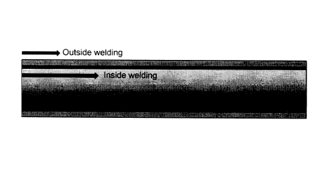
FIG. 6shows a cross-sectional picture of the weld zone produced by
performing the submerged arc welding for both of the inside and outside
- 24 -
CA 02861671 2014-09-02
_ .
welding and a cross-sectional picture of the weld zone produced by leading
with
the tungsten arc welding for the inside welding and following with the
submerged arc welding for the outside welding . As shown in FIG. 6, the size
of
the inside weld zone using the tungsten arc welding is relatively small,
compared with the size of the outside weld zone using the submerged arc
welding. The point that the size of the weld zone is small means that the area
of a heat-affected zone is small. Since the heat-affected zone is small,
deformation also occurs less.
As described above, the combination welding method leading with the
io tungsten arc welding method for the inside welding of the steel pipe and
following with the submerged arc welding method for the outside welding of the
steel pipe by keeping the predetermined separation distance from the tungsten
arc weld zone solves the problems of the conventional combination welding
method by firstly performing the submerged arc welding to the inside surface
of
the steel pipe and secondarily performing the submerged arc welding to the
outside surface of the steel pipeafter the electric resistance welding. That
is,
the combination welding method according to the present invention solves the
conventional combination welding method's problem in that even though the
outside welding is made, the extent of bending which is sufficient to correct
the
extent of bending which occurred upon the inside welding to the original state
does not occur upon the outside welding. Further, the combination welding
method according to the present invention solves the conventional combination
welding method's other problem in that, when the inside welding and the
outside welding are simultaneously proceeding, since the flux drops
downwardly,
- 25 -
CA 02861671 2014-09-02
it is impossible to perform normal welding. In the combination welding method
according to the present invention, since the inside welding and the outside
welding are simultaneously proceeding by keeping the predetermined
separation distance, generally the welding time is shortened. Furthermore,
since the outside welding is performed before the fusion area reaches below
the
Al transformation point after the inside welding, the bending of the steel
pipe is
properly controlled after the welding and therefore the straightening time in
the
post-process is shortened.
The invention has been described using preferred exemplary
embodiments. However, it is to be understood that the scope of the invention
is
not limited to the disclosed embodiments. On the contrary, the scope of the
invention is intended to include various modifications and alternative
arrangements within the capabilities of persons skilled in the art using
presently
known or future technologies and equivalents. The scope of the claims,
therefore, should be accorded the broadest interpretation so as to encompass
all such modifications and similar arrangements.
- 26 -