Note: Descriptions are shown in the official language in which they were submitted.
CA 02861683 2014-09-04
AN APPARATUS FOR HARVESTING ELECTRICITY AND IRRIGATION USING HELICAL
TURBINES IN A VORTEX USING SPIRALING PIPELINES AND THE PROCESS FOR
EXTRUDING THE SAID PIPELINES
Inventor: Audet, Romain O., Bachelor of Science, Bachelor of Commerce
(Gatineau, Quebec, Canada)
ABSTRACT
An apparatus is disclosed of a tornado shaped body, called a HUG, (Helical
Unique Generation), with a rotating helical turbine to harness electricity or
to
rotate a large pump used for irrigation or fluid transfer of laminar flows
using a
spiraling pipeline with spiraling striations.
This apparatus is capable of creating a vortex to increase the velocity of
laminar
flows. The rotary motion of the turbine can also rotate a large pump which is
used for irrigation or fluid transfer of laminar flows without the use of
electricity.
Fluids like water, natural gas, oil or other gases can be transferred by the
HUG
Pipeline more efficiently using a natural laminar flow, without friction
produced on
the inside of the pipeline.
DESCRIPTION: Field of Invention
The HUG uses the physics of the vortex to create a spiralling motion to
accelerate the flow of fluid to generate electricity or irrigation pumps from
the
water flow from tidal flows, rivers, rapids, ocean and other fluid flows using
a
helical turbine and to transfer this fluid like oil or natural gas at near
zero friction.
Discussion of Prior Art
The "prior art" helical turbine is used to provide rotation to either the
submersible
pump or the electrical generator. One of the companies¨GCK Technologies Inc.
has a patented turbine using the helical blade. Lucid Energy Technologies
patented the same helical turbine in a pipeline, but there is no vortex
claimed for
either patents. An extensive search was done by a professional patent searcher
and the closest patent, US840520, is explained as an "augmented velocity hydro-
electric turbine generator". A vortex is mentioned, but the patent is
different since
there are no spiralling pipes, only a straight pipe with some indication of
striations.
All these prior systems do not use the physics of the vortex in order to
increase
the velocity of the laminar flow. None of these patents experience negative
pressure or a sucking action at its entrance, which is created by the action
of the
vortex in the HUG. Hence, all these companies have patents for much larger and
more expensive turbines.
1
CA 02861683 2014-09-04
Background of Invention
The natural motion of fluid is a vortex, which creates a laminar flow. This
kind of
motion accelerates and contracts the flow of fluid. There are less molecular
collisions, which would interfere with the laminar flow.
Summary of the Invention
A helical turbine, 23, is disclosed , which creates electricity from laminar
flowing
water or oil that eliminates the expensive electrical control systems.
A said helical turbine connects directly to a submersible pump, which
constantly
pumps water into the HUG Funnel as shown in Figure 3, which is connected to a
generator, 27.
The pumped water keeps the bowl of the said funnel always filled to the top.
This
creates an unchanging pressure on the helical turbine. The connected generator
is custom designed for this specific unchanging rotation. This said generator
creates constant unchanging 60 Hz cycle AC current without the use of an
elaborate expensive electrical control system, which is designed for the
electrical
grid.
Whenever you have a new product, there are always many applications or spin
offs, which I name by their function: the Waterfall HUG, the 'Run of the
River'
HUG, the HUG Pump, the Irrigation HUG, the River HUG, the Pylon HUG, the
Ocean HUG, the Tidal HUG, the HUG Pipe or Pipeline and the Recycle HUG,
and in general, the HUG Power Systems:
The Waterfall HUG at Figure 1 doesn't require any expensive control sys-
tem to adjust the electrical current. Electricity is created at the source in
the
standard AC current required by the electrical grid.
The 'Run of River' HUG use a trough, 69, with a gradual slope to feed the
flow into its funnel, 11, as shown at Figure14, in order to create
electricity.
The HUG Pump has a helical turbine, 23, shown in Figure 3 and 4, which
is connected directly to a submersible pump for irrigation or water transfer
without using any electricity. The submersible pump can also be used to pump
water into a HUG Funnel located above, which activates another helical turbine
in order to create electricity.
The Irrigation HUG has a helical turbine,23, which is connected directly
to a submersible pump, which constantly pumps water (Figure 3) without the use
of electricity or diesel.
2
CA 02861683 2014-09-04
The River HUG has an energy system at its entrance, which doubles the
velocity of the river flow before entering the vortex of the HUG.
The Pylon HUG also doubles the velocity before the flow enters the
vortex of the HUG, which increases the velocity of the laminar flow by four
times.
The Ocean HUG vortex increases this velocity by four times. The ocean
current has an average velocity of 1.5 m/sec and can reach 2.5 m/sec in con-
stricted areas between islands, which is much less than the threshold velocity
of
3.1 m/sec. required to create electricity. The HUG Funnels are placed on a hex-
agonal series of anchored structures above the HUG Pumps. Their generators,
27, are kept dry as shown in Figures 9 and 12.
The Tidal HUG design has similar features compared to the Ocean HUG.
The HUG Pump with its submersible pump turns toward the reversing direction
of the tide using an attached underwater kite. Water is pumped above to a
Funnel HUG, which activates another helical turbine. This turbine powers a
generator, which creates electricity.
The HUG Pipe and Pipeline has striations, 31, which aligns the laminar
flow in the shape of a vortex or whirlpool. This results in a higher velocity
of the
laminar flow of fluid. There is less friction in this pipeline because a
boundary
layer has developed between the main vortex and a series of mini vortexes
created by the said striations. The exact angle and arrangement of the
striations
are not revealed in this patent. Without the information in this black box of
information, our research has shown that the HUG will not perform as
described.
Fluids can be transferred through an ocean between two geographic
locations over 500 km (300 miles). The maximum distance is now only 80 km
using today's technology. Fluids like water, natural gas, oil or other gases
can be
transferred by this said HUG Pipeline more efficiently using a natural laminar
flow, without friction produced on the inside of the pipeline.
The Recycle HUG is designed to increase the high velocity of a laminar
flow, from a vortex of gray water. Gray water can be pumped to the toilet
reservoir of the same story of a high building, without the use of
electricity. The
gray water reservoir, 37, services its own floor of a high rise building. The
modular HUG can replace the section of the sewage pipe, without major
renovations, while saving electricity used to pump new water from the ground
level. The gray water is pumped into a toilet reservoir on the same floor,
which
has its own riser.
Brief Description of the Drawings:
Various changes may be made without departing from the spirit of the
invention:
3
CA 02861683 2014-09-04
Figure 1: Water is directed into the HUG Funnel, 11, through a trough, 69. The
design of the said funnel creates or vortex action like a whirlpool, ending
its
journey pass the helical turbine, 23, after increasing its velocity several
times.
The rotation of the said turbine is mechanically connected to a specially
wired
generator for that steady unchanging rotation, which is caused by the steady
pressure of the maximum height of the water level of the said funnel, so there
is
no need for elaborate electrical control systems. The HUG Energy System is
designed to output 60 Hz AC current for the grid.
Figure 2: These Multiple Funnel HUGs,11, are necessary to handle the changing
volume of the waterfall. The minimal flow of the waterfall can be handled by
only
one said Funnel HUG. In the spring of the year, the extra power can be
captured
by additional Funnel HUGs, which overflow into each other, and, which are fed
by a water tower and controlled by a modulated control valve,43, as shown in
Figure A. The Figure B shows the interconnection between two Funnel HUGs,
which help to create a vortex. Figure C and D shows the striations of the
vanes, 4.
and the steady height of the water in the water tower maintains a steady
pressure on the helical turbines, thereby avoiding an expensive electrical
control
substation.
Figure 3: The Pump HUG, 62, adds another use of the HUG, to create electricity
from fast moving water. The power house, 47, is supported over a fast water
source, to protect and provide easy maintenance of the said HUGs. Figure A
shows the HUG Funnel, 11, which is always filled to the top, by the
submersible
pumps, 67, in the fast flow. The modulated control valve, 43, monitors the
height
of the water to the top of the said Funnel, which assures a steady rotation of
the
specially wired generator, 27, which in turn produces a steady 60 Hz AC
current
acceptable to the electrical grid.
Figure 4: Figure A shows the power house, 47, which is supported by a barge,
63, over a fast water source, to protect and provide easy maintenance of the
said
Pump HUG, 62. The water flow enters the said Pump HUG through a trash
screen, 7, as shown in Figure C, and continues pass a vane ring, 46, shown by
the three dimensional image, D, which uses the physics of the Coanda effect as
demonstrated at Figure E. The flow is redirected past a cone cover, 55, at
Figure
F and enters into the spiralling HUG pipes, which are angled and directed
toward a helical turbine, 23, which rotates a pump, 67.
The said pump, as shown in Figure C, delivers water to the highest level of
the
HUG Funnel, 11, by a spiralling pipeline, 68, as shown in Figure A. The second
turbine, 23, rotates a generator, 27, in order to create electricity.
A steel pipe connector, 96, at Figure G, along with the metal armour, 97 at
Figure
H, adds strength to the rotation of the shaft of the turbine.
Maintenance of the said Pump HUG is done using a crane, 61, inside the said
4
CA 02861683 2014-09-04
power house, on a said barge, which is supported by anchors, 64. Figure B
shows the detachable hinged door, 33, on which both the said turbine and the
said pump are attached, which provide easy maintenance.
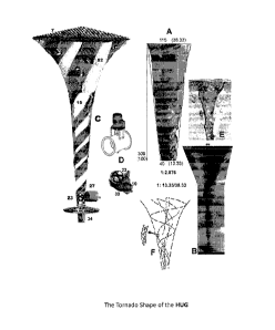
Figure 5 illustrates the basis of the design of the HUG,15, based on the shape
of
the tornado, 66, shown in figure B. The figure A shows the mathematical slope
of
the narrow body of the said HUG: 1: 2.88. The trash screen, 7, protects
against
any debris. The detachable door, 33, has both the said turbine and the
generator
attached for easy replacement. A steel pipe connector, 96, at Figure D, adds
strength to the rotation of the shaft for the turbine and generator. Figure D
shows
the protective generator cover, 10, which shields the generator, 27, from
water
damage. Figure E show nature's shape of a vortex, while Figure F shows a
schematic flow of a vortex.
Figure 6: The Pump HUG, 62, has submersible pumps, 67, which are connected
by HUG Pipes, 68, on the floating hexagonal system, 73, above. The said
pumps fill the level of the said Funnel HUGs,11, above, thereby guaranteeing a
steady pressure on the helical turbine, 23, shown in figure C, which provides
a
steady rotation to the generator, 27. The protective cover,10, shields the
said
generator from water damage. The underwater kite, 70, turns the said Funnel
HUG system automatically to face the reversing direction of the tide. The said
kite is held at the anchor, 64, not unlike a normal kite, which has a tail,
50.
Figure 7: The Tidal HUG has an attached "prior art" underwater kite, 70, which
turns automatically to face the tide. The said kite has a tail, 50, and an
anchor, 64,
which is not unlike a real kite, except it has a stronger design.
Figure 8: In the ocean current, the Pump HUG, 62, rotate a helical turbines,
23.
as shown in figure B. These said pumps are connected to HUG Pipes, 68, which
direct water up to the Funnel HUGs at the ocean surface located on the
floating
hexagonal barges,73. The tail, 50 keeps the direction of the HUG system in
line
with the current, while the anchor, 64, stabilizes the said system on the
ocean
floor. A crane, 61, serves to raise the said HUGs through the opening of the
said
hexagonal barge, for maintenance purposes.
Figure 9: The farms of HUGs in an ocean current The figure C shows the
average velocity of an ocean current of 1.5 m/sec., while the threshold of a
velocity of 3.1 m/sec is required for any commercial application to create
electricity from an ocean current. The physics of the vortex increases this
slow
velocity by a factor of several times above 6 m/sec.
The Funnel HUGs,11, are installed on a hexagonal barge, 73, in groups of six
HUGs on many hexagonal barges is shown at figure B. The said barges are held
at the bottom of the ocean floor by a set of tethers,17, using tether spring
systems,16. The said farm of HUGs are attached to a tower, 51, which is
anchored securely on the ocean floor as shown in figure A not unlike a modern
CA 02861683 2014-09-04
ocean going oil rig. The said tower houses a substation, 42, for electricity
from
each of the said hexagonal barges.
Figure 10 The HUG Pipe Striations The striations, 31, are drawn at A, A', A",
shown at Figures C, in a spiralling pathway along the entire pipe. Figure D
shows the spiralling pipelines, which reduce in size to a slope, m, of .05 in
the
Pump HUG, 62. Figure B shows the compact pipe that is inserted as a "c" shape
and later pressurized to fit snuggly inside another pipe to be refurbished.
The
exact angle and arrangement of the striations are not revealed in this patent,
but
our research has shown that the angle and the configuration are critical
especially when the HUG is placed in a horizontal position.
Figure 11: The commercial electricity and irrigation system concentrates on
providing both irrigation and electricity. The semi-submergible barge, 8,
holds a
series of Pump HUG, 62, having attached helical turbine, 23, which in turn
rotates a large submersible pump, 27. Each of the said pumps are connected to
a HUG Pipe, 68, which deliver pressurized water to the Funnel HUG,11, located
in a housed facility on shore. This pressurized water fills the said Funnel
HUG to
the top using a modulated control valve, 87, which continues to feed a the HUG
Pipeline, 68, for irrigation. This vortex created in the said Funnel HUG
energizes
the helical turbine, 23, which in turn, rotates a generator, 27, to create
electricity.
Figure 12: The Pump HUG, 62, captures energy from an ocean current, which
are powered mechanically by a series of helical turbines, 23. These said pumps
are connected to HUG Pipe, 68, which direct water up to the Funnel HUGs at
the ocean surface located on hexagonal barges, 73. The anchor system
stabilizes the said semi submersible barges, 8, on the ocean floor. The "prior
art"
tether spring system, 16, eliminates jarring motion, while the slack line, 18,
offers
additional security to the tether, 17. The semi submersible system, 8 is shown
at
plan view, B and the front view, A.
Figure 13 The Pump HUG, 62, in figure A, captures electrical power from the
fast moving convergence of water of a river at the rear of a pylon, 22, of a
bridge.
The helical turbines, 23, powers by the submersible pumps, 67, which in turn
pumps water through the HUG Pipes, 29, to the top of the funnel, 11. The water
in the said funnel is always filled to the top, monitored by a modulated
control
valve, which guarantee a steady pressure on the helical turbine, 23, which
drives
the generator, thereby creating 60Hz AC current for the electrical grid. The
crane,
61, is used to raise the submersible HUG pumps for maintenance purposes. The
energy body,1, concentrates and speeds up the flow. This said energy body is
attached around the pylon of a bridge in figure A or is placed on a slab in
the
center of the flow as shown in figure B.
Figure 14 The Funnel HUG, 11, in figure B, shows a trough, 69, in a 'run of
the
river' system, which connects from a stream or a river to the said Funnel HUG
that creates a vortex of water as it flows pass and energizes the helical
turbine,
6
CA 02861683 2014-09-04
23, which powers the generator in order to create electricity. A modulated
control
valve monitors the maximum height of the water in the said Funnel and the
steady rotation of the said turbine allows the generator to be calibrated to
always
produce 60 Hz AC current without the expensive electrical control system.
Figure C shows the alternative method of Run of the River. Traditional Run of
the River Pipelines develop a high amount of friction along the inside of
their
pipeline. In contrast, the HUG has superior power generation because of the
physics of the vortex, which creates a more than doubling of velocity of the
flow
to the said turbines..
Figure 15 The tidal flow enters the automatic tidal gates, 38, which close
when
the flow of the tide is reversed. The captured water from the flood of the
tide in a
bay is forced into the inlets of the water tower, 51, shown at Figure B. The
said
water tower is used to maintain a steady pressure on the helical turbine and
the
steady rotating pressure of the generator, 27, which is monitored by a
modulated
control valve, 43, thereby avoiding an expensive electrical control
substation. The
power generation from the Funnel HUGs, 11, is created continuously, longer
than the time taken for a new flood of the tide.
Figure 16 Reviving Old Decommissioned Dams There is usually a buildup of silt,
25, behind the dam,12, after 25 to 50 years of use as shown in Figure A and B.
One solution to reviving the dam is to bypass the turbines of the dam
completely
and allow an overflow the water over the dam into the HUG Funnel. The helical
turbine, 23, creates a large amount of energy, which is transferred to the
generator, 27, in Figure C.
Figure 17 Power from the Dam Tail race is available, which can be gleaned from
the rush of water coming out of the tail race of every dam after it leaves the
propeller of the dam. The Figure A is explained in Figure 3 above. The
transmission lines add additional power to the present dam.
Figure 18 It is possible to constrict a narrow channel in a stream or river
for a
power diversion at an island in a river by constructing a small earth, stone
and
rock dam,12, shown as Figure A, where the main thrust of the river flow, which
is
known as the "thalweg", 29, has the highest velocity of a meandering river.
The
man-made energy bodies, 24, in front of the HUG aligns a faster laminar flow
as
shown in figure B. There is an increase in the velocity of the laminar flow
because of the Coanda Effect The said energy body is place on wide base and
lowered by a crane to the river bottom.
Figure 19 The Water Transfer Experiment
This table top experiment shows that a glass pipe,13, (B) and straight copper
(C)
pipes was actually found to be the least suitable for fluid transfer, which
have a
high coefficient of friction. The most interesting HUG Pipe (D) has the least
friction. The movement of all the water in the said pipe, is faster than in
7
CA 02861683 2014-09-04
conventional cylindrical pipes because of laminar flow.
A graph of the experiment shows the results of our investigation: the spiral
pipe
(D) produces a markedly different profile to those of the other straight round
test-
pipes. On three occasions, the actual time that it takes to siphon the water
does
dip close to the line of zero on the graph, which indicate a laminar flow and
zero
friction. This laminar flow happens at specific critical pressure points.
Figure 20 Figure A shows the Funnel HUG,11, which increases the velocity of a
laminar flow of gray water. Figure D shows the vanes explained in Figure 2
above.
Figure E shows the vane ring, 46, which creates a Coanda effect at the throat
of
the HUG and the vortex increases the velocity of the flow at the helical
turbine,
23, shown in Figure C, which rotates a submersible pump, 67. The modulated
control valve opens the collapsible doors, 5, is controlled by a modulated
control
valve, 87, causing a release of the gray water of a reservoir within the said
HUG,
when it is filled. Gray water can then be pumped from the gray water
reservoir,
37, to the toilet or black water reservoir,19, on the same floor, without the
use of
electricity. Figure F shows the top view, while Figure B shows the expansion
required to fit the HUG in a sewerage pipe, 13.
The maintenance door, 33, which houses both the said turbine and the pump, 67,
allows for easy access to both. Accessible grease or zerk fittings allow for
easy
maintenance without detaching the said door. Figure D shows the vanes which
start the vortex action. In one embodiment, the inside lining of the HUG has a
rifling of striations described in Figure 10.
Figure 21 shows the process of extruding intertwining helicoidally multiple of
HUG Pipelines, 84. This cross-sectional elevation view illustrates a "prior
art"
extruder for manufacturing of pipelines and pipes. The extruder, 82, shown at
A,
uses a screw, 93, to produces several spiralling pipes. The die, 86, produces
the
shape of the pipeline, which is pulled by a traction system, 79, through the
vacuum table, 85 and then to a saw, 78. The tipping table is the last step of
the
process, which is located at the end a long bed trailer, that is pulled by a
motorized vehicle like a track mobile for uneven ground, 95, or a truck on
level
ground for delivery into an open trench. The motor, 92, and the heat needed to
melt the PVC pellets in the hopper, 77, comes from electricity produced by a
diesel engine, 44, shown at B.
Figure 22 The water tower in Figure A serves to provide a steady water
pressure
using a modulated control valve, 97, of water entering a HUG Funnel. Several
Tiers of turbines,23, and generators, 27, are separated by a distance of 5.2 m
in
order to realign to a laminar flow. The metal armour and connectors, 96, lend
support to the shaft of the helical turbine. Figure B shows a three-dimension
embodiment where an external metal armour, 97, protects the said HUG. In a
further embodiment, the striations or rifling along the inside lining of the
said
HUG maintains the vortex.
8
CA 02861683 2014-09-04
Figure 23 The design of the Waterfall HUG shows the suitability for a
waterfall
and how the said HUG, can be incorporated directly into a waterfall. A
construction site is excavated in front of a waterfall. The said powerhouse
itself
can be made more attractive as illustrated by an architectural construction,
5.
Each helical turbine, 23, is attached to an electrical generator, 27, which is
attached to a detachable hinged doors, 33, and which is spaced at a distance
of
5.2 m from each other. The said hinged doors can be released and raised from
the said HUG using a warehouse crane, 61, for maintenance purposes.
More Description: the HUG increases the velocity of the laminar flow as
follows:
= The Cycloid Spiral Motion in a HUG forces the laminar flow to "roll"
inward
around the axis of motion of the water's flow. This natural kind of motion
tends
to accelerate and align the stream of water along its path in a spiraling
pipeline with spiraling striations.
= An Energy Cone, 24, which is located at the front entrance of the HUG,
uses
the physics of the Coanda Effect, 39, the tendency of a stream of fluid to
stay
attached to a convex surface, rather than follow a straight line in its
original
direction. The ambient water besides this constricted laminar flow is swept
along where they intermingle and align at higher velocity as shown in Fig.13.
= Striations, 31, form a striated surface in order to give a rotary motion
to the
laminar flow. The striations are the inside walls of the HUG, which are
created from plastic intrusion. These striations produce a multiple rifling
effect.
This causes the laminar flow to move in a general spiral motion. The
striations
align the laminar flow in a clockwise manner in the Northern Hemisphere and
anti-clockwise in the Southern Hemisphere.
= The Double Spiral Vortex Creator
The HUG Pump, 62, operates in a horizontal position and it can be less af-
fected by gravitational forces, which are necessary for a strong vortex. This
patent discloses a double spiral vortex creation, which creates such a vortex.
The spiraling effect along the wall acts like ball bearings. A longitudinal
vortex
develops along the inside of the HUG without any friction and the velocity of
the laminar flow increases by four times.
= The Venturi Effect, 52, cause the constricting ducts to reduce this water
flow
by one-half the original size, which doubles the velocity of the flow before
it
enters the vortex entrance of the HUG.
9
CA 02861683 2014-09-04
Numerical Description of Drawings
1 Energy Body 48 Vortex
2 HUG Housing 49 Sea Level
3 Boundary Layer 50 Tail Construction
4 Vane 51 Water Tower Construction
Architectural Construction 52 Venturi Funnel
6 Flow 53 Leveling Vessel
7 Trash Screen 54 Barrier
8 Semi-submerged Barge 55 Cone Cover
9 Natural Islands 56 Cone
Protective Cover for Generator 57 Floral Design
11 Funnel HUG 58 Winching Cable
12 Dam 59 Angle Marker
13 Pipe 60 Head
14 Float 61 Crane
HUG 62 Pump HUG
16 Spring System for Tether 63 Barge
17 Tether 64 Anchor
_
18 Slack Line 65 Overflow
19 Black Water or Toilet Reservoir 66 Tornado Shape
Shore 67 Large Submersible Pump
21 Bridge 68 Spiralling HUG Pipe
22 Pylon 69 Trough
23 Helical Turbine 70 Underwater Kite
CA 02861683 2014-09-04
24 Energy Cone 71 Kite Anchor
25 Silt 72 Irrigation Housing
26 Electrical Connection 73 Hexagonal Floating Barge
27 Sealed Generator 74 Water or Fluid Pipeline
28 Striated Wall of Pipeline 75 Water Supply
29 Twalweg 76 Tipping Table
30 Automatic Tidal Gate 77 Hopper
31 Striations 78 Saw
32 Buoy 79 Traction
33 Detachable Hinged Door 80 Grease Fitting or Zerk
34 Outlet 81 Warming Cover
35 Rise 82 Multi-Twin Screw Extruder
36 Angle 84 Extruded HUG Pipeline
37 Reservoir 85 Vacuum Bath
38 Tidal Barrier 86 Die
39 Coanda Effect 87 Modulated Control Valve
40 Winch 92 Motor
42 Substation Control System 93 Screw
43 Modulated Control Valve 94 Low Bed Trailer
44 Diesel: 340 kW 95 Mobile Vehicle with tracks
45 Run-of-River Hydro Electric Power 96 Metal Pipe Connection
46 Vane Ring 97 Metal Armour
47 Power House 98 HUG Compact Pipe
The Embodiments of the Invention, in which an Exclusive Property is
Claimed, are defined as follows:
11
CA 02861683 2014-09-04
An apparatus is disclosed of a torpedo shaped body, called a HUG, (Helical
Unique Generation), which operates with a low water head, a waterfall or a
fast
current engaging a rotating helical turbine, which rotates a large pump used
for
irrigation or fluid transfer using a spiralling pipes with spiralling
striations.
This apparatus is capable of creating a vortex to increase the velocity of the
fluid
flow. This vortex reduces resistance by curving more and more inwards thereby
avoiding the confrontational resistance of straight motion. The rotary motion
of
the turbine can also rotate a large pump which is used for irrigation or fluid
transfer without the use of electricity.
The HUG uses the physics of the vortex to create a spiralling motion to
accelerate the water flow from tidal flows, rivers, rapids, ocean and other
currents
rotating a helical turbine, which, in turn, rotates a large dimension pump. In
combination with a submersible pump, water is pumped to a second funnel-
shaped HUG, which is used to create electricity.
The present invention is not limited to the embodiments described below, but
encompasses any and all embodiments within the spirit of the following claims:
I CLAIM
1. an apparatus to accelerate an already fast flow of water by creating a
vortex
of a fluid flow of high velocity into a multitude of spiralling pipes or into
a funnel,
which is shaped like a tornado, and which engages a "helical" turbine to
rotate a
large dimension pump, used for water transfer or irrigation and/ or for the
creation of electricity, referred to hereafter generally as HUG (Helical
Unique
Generation):
= comprising a "prior art" set of three to six blades of the said helical
turbines,
having a shape, to fit into body of the HUG, having a shape of a torpedo,
which faces the water flow, hereafter referred to as Pump HUG, and;
= comprising of spiraling striations, on the inside lining of the said
pipeline,
which create a serpentine route for the water flow, at an angle, which is a
function of the velocity of the flow, and;
= comprising of a Venturi inlet and a vane ring, which constrict the flow
at the
entrance of the HUG, in order to increase the velocity of the flow, and;
= in a different embodiment, the said Pump HUG, having spiraling pipes,
which
gradually diminish in size with a slope of.05, which forms tighter turns along
its length in order to increase the velocity of the vortex, and;
= comprising of a large trash screen, to protect against large debris, and;
= having neighboring interconnected HUGs, which can be built in arrays
facing
the current aligned beside each other, and;
= including in one embodiment, each plurality of HUGs to follow each other
at a
distance exceeding 5.2 meters along the same current, and;
12
CA 02861683 2014-09-04
2. in another embodiment, water is pumped from the said Pump HUG into a
funnel-shaped apparatus, hereafter referred to as a Funnel HUG, which has the
shape of a tornado in order to create electricity, and;
= comprising of vanes located at the top of the inside edge of the funnel
that
help to direct the flow toward the center into a vortex of fast water, and;
= in a different embodiment for a different use, and apparatus, into which
water
from the waterfall is directed into the Funnel HUGs by a trough, and; the
tornado shape of the said funnel creates a whirlpool or vortex action, which
increases the velocity of the flow by multiple times, and; thereby increasing
the rotation of a second turbine together with the same increased rotation of
a
specially wired generator, and a steady electrical output of unchanging 60 Hz
AC current suitable for the grid, which is caused by the steady unchanging
maximum height of the water level of the said funnel, and;
= including in a different embodiment a semi-submersible, upper structure,
called a power house, for rapids or other currents, which is supported by
floats that are tethered by a set of variable winch devices, which can be
disconnected from its mooring lines and cables and towed to a shore-based
support facility, and used to accommodate the Funnel HUGs and their
electric power generator, and; a large opening in the said power house, which
provides easy access to replace or maintain the said Pump HUGs, located
below the surface of the fast current, which are used to pump water into the
said Funnel HUG, and;
= including introducing the initial flow into a water tower, which is
monitored by
a modular control valve to control the flow so that the steady height of the
water in the water tower maintains a steady pressure on the helical turbines,
and a steady pressure on the rotation of the connected generator, which is
wired to produce a specific 60 Hz AC current, and thereby avoiding an
expensive electrical control substation, and;
3. in one embodiment, for a different use for the HUG, as defined in Claim 1
and
Claim 2, which incorporates the Pump HUGs designed to capture energy from
ocean currents and deep river currents, located below a hexagonal semi
submersible structure or a barge, and;
= located below the ocean surface turbulence at the minimum 15 to 50 m
depth
level, or over one meter depth in deep rivers, and;
= having helical turbine(s), which are connected directly to a submersible
pumps used to fill water to the top of a Funnel HUG on the said barge above,
which activates a second helical turbine that rotate an electric generator in
order to create electricity, and;
= comprising of an on board crane, located on an open hexagonal upper struc-
ture or barges, which has a large central opening to the water flow so that
the
said Pump HUG can be retrieved for maintenance purposes, and;
= comprising of a tail system at the rear of the semi-submersible structure
in
order to provide stability in the ocean currents, and;
= including in another embodiment nearer the shore of a current, the
placing of
a platform, not unlike the modern oil drilling platform, which is bottom
13
CA 02861683 2014-09-04
supported, in order to provide a stable location for the electrical control
systems of multiple said hexagonal open structures or barges and;
= for a different use in a tide, comprising of Pump HUGs, similar to the em-
bodiment for an ocean current described above, with an additional attached
"prior art" underwater kite system, which performs like a flying kite, in
order to
keep the said HUG always facing the changing tidal current, and;
4. there are as many other embodiments as there are different uses for the
HUG,
as defined in claim 1 and claim 2, which use the same physics of the energy of
the vortex:
= including in a further embodiment for a different use, by allowing the
flood of
the tide to enter in the large one-way doors in the tidal barrier, which is
constructed transversely in an ocean bay or passage and at the outlet, an
array of Funnel HUGs are installed near the tidal barrier in order to extract
energy from the ebb tidal flow, and;
= including in a different embodiment for a different use, while the
traditional
'Run of River' system uses a gradual slope to feed the head of flow into a
straight pipeline directed to a turbine located at the bottom of the system,
instead, an adjoining Funnel HUG, to which the said flow is redirected and
monitored by a modulated control valve, in order to create electricity at more
than twice the efficiency because of the power of the vortex, and;
= including in a different embodiment for a different use, a man-made
"energy
body", concave- wedge shaped forms which is bottom-supported on the river
bed, and having a slightly elongated egg-shaped cross section and having a
height to fit in front of the said Pump HUGs, creating the Coanda effect, for
torrent confinement of the river, and;
= including in a different embodiment for a different use, a said energy
body to
be formed around the pylon of a bridge or placed on a slab in the center of a
water flow, which creates the Coanda effect to increase the velocity before
the flow enters the vortex of the said Pump HUG, and;
= including in another embodiment, for a different use, an adjoining Funnel
HUG is built alongside an urban water tower, and allowing the high water
level of the said water tower to feed into the said Funnel HUG during non-
peak times in order to recover emergency electricity as required, but at lower
pressure during normal times, which is monitored by a timed modulated
control valve, and an override switch, which revives the water tower pressure,
and;
= including in a different embodiment for a different use, a Waterfall HUG
design can be incorporated directly into a waterfall, and;
5. in another embodiment, an apparatus, called the HUG Pipeline with a
multitude of spiralling striations or rifling, designed to create a vortex in
order to
increase the velocity of a laminar flow of fluid , such as water, natural gas
or oil:
14
CA 02861683 2014-09-04
= comprising of a multitude of intertwining pipelines with a normal round
cross
section, spiralling around itself like a rope or, alternatively around a
straight
pipeline, the spirals of which create smaller vortexes that act like ball
bearings
to provide a larger central vortex of laminar flow, which has near zero
friction,
and created by plastic extrusion and;
= in a similar embodiment as above, comprising of a multitude of
intertwining
pipes, in which each pipe has a cross section of a horn, not unlike the shape
of a bean, and;
6. in another embodiment, an apparatus, called the Recycle HUG used to
transfer grey water in its reservoir to a toilet reservoir on the same floor
level,
and, within a large sewage pipe, or alternatively within a slightly enlarged
section
of the sewage pipe, and;
= comprising of a temporary reservoir in the shape of a tornado, located
directly
on top of the said HUG, in order to create a vortex, and; to be released
automatically when filled through a modulated control valve, and;
= having a set of vanes, in order to start a vortex action, which is
described
above in the Funnel HUG, as defined in claim 2, and;
= engaging a helical turbine, which rotates a pump, used to transfer grey
water
from its own second reservoir located below the exit of the said HUG, and;
= pumping the grey water to a higher toilet reservoir on the same floor
level,
and;
7. a process of extruding a seamless spiralling multitude of intertwining
pipelines
beginning with a "prior art" plastic pipe extrusion system, located on a motor-
driven low bed trailer and powered by a diesel engine, and adding the process
where each pipeline combines together in a stationary multi-hole core, and fed
through a rotating multi-hole core, which provides a twisting action, all
located
within the heated environment of the said extrusion system, located on the
said
low bed trailer for delivery of said seamless spiralling pipeline into a
prepared
trench, and;
8. a HUG pipe with striations, described in Claim 1, and fed through a "prior
art"
rotary drive die nozzle machine for an extruder and comprising of at least one
rotatable nozzle and a drive assembly including at least one drive gear
rotates at
least one nozzle in order to perform the spiraling action and a HUG Compact
pipe is fabricates with a "prior art" extrusion system, extruded as a circular
polyethylene pressure pipe then folded into a "C" shape, acting as a close fit
liner
that is specially designed for rehabilitating damaged potable water or oil
pipelines,
and when heated up by steam, it regains its original round shape and adjusts
to
the wall of the existing pipe, so reducing its cross section, and fed into the
pipeline at one end, lubricated at the bottom and pulled at the other end by a
winch cable, having a "memory effect", meaning that the pipe reverts to its
circular shape when heat from the steam is applied and pressurized air is used
during the cooling process.