Note: Descriptions are shown in the official language in which they were submitted.
PIPE DRIVE SEALING SYSTEM AND METHOD
BACKGROUND
[0001] Present embodiments relate generally to the field of drilling and
processing of
wells, and, more particularly, to a pipe drive system for coupling with and
releasing drillpipe
elements to facilitate insertion and removal of the drillpipe elements into
and out of a
wellbore during drilling operations and the like.
[0002] In conventional oil and gas operations, a drilling rig is used to
drill a wellbore to
a desired depth using a drill string, which includes drillpipe, drill collars
and a bottom hole
drilling assembly. During drilling, the drill string may be turned by a rotary
table and kelly
assembly or by a top drive to facilitate the act of drilling. As the drill
string progresses down
hole, additional drillpipe is added to the drill string.
100031 During drilling of the well, the drilling rig may be used to insert
joints or stands
(e.g., multiple coupled joints) of drillpipe into the wellbore. Similarly, the
drilling rig may
be used to remove drillpipe from the wellbore. As an example, during insertion
of drillpipe
into the wellbore by a traditional operation, each drillpipe element (e.g.,
each joint or stand)
is coupled to an attachment feature that is in turn lifted by a traveling
block of the drilling
rig such that the drillpipe element is positioned over the wellbore. An
initial drillpipe
element may be positioned in the wellbore and held in place by gripping
devices near the rig
floor, such as slips. Subsequent drillpipe elements may then be coupled to the
existing
drillpipe elements in the wellbore to continue formation of the drill string.
Once attached,
the drillpipe element and remaining drill string may be held in place by an
elevator and
released from the gripping devices (e.g., slips) such that the drill string
can be lowered into
the wellbore. Once the drill string is in place, the gripping devices can be
reengaged to hold
the drill string such that the elevator can be released and the process of
attaching drillpipe
elements can be started again. Similar procedures may be utilized for removing
drillpipe
from the wellbore.
1
CA 2861770 2018-01-02
[0004] Drillpipe is traditionally controlled during drilling using a
screwed-in sub below
the quill of a top drive. It is now recognized that certain aspects of these
existing techniques
are inefficient because of limitations on other procedural components during
certain phases
of operation.
BRIEF DESCRIPTION
[0005] In accordance with one aspect of the invention, a pipe drive system
is provided.
The pipe drive system includes a gripping device configured to engage a
drillpipe element
and a top drive configured to impart rotational force to the gripping device.
Additionally,
the system includes a housing of the gripping device configured to extend over
and at least
partially around a distal end of the drillpipe element. Further, the system
includes a seal area
positioned along an inner perimeter of the housing such that, when a seal is
inserted in the
seal area, the seal is arranged to engage with a face of the distal end of the
drillpipe element
and a face of the gripping device. Further still, the system includes
engagement features of
the gripping device configured to extend inwardly from the inner perimeter to
facilitate
coupling of the gripping device with an outer circumferential area of the
drillpipe element.
[0006] In accordance with one aspect of the invention, a gripping device is
provided. The
gripping device includes a housing including a receptacle, wherein the
receptacle includes a
receptacle face and a receptacle boundary extending from a perimeter of the
receptacle face.
Additionally, the gripping device includes an engagement feature coupled with
the housing
and configured to be actuated to engage an outer circumferential area of a
drillpipe element
when the housing is extending over a distal end of the drillpipe element.
Further, the
gripping device includes a seal positioned within an inner boundary of the
housing, wherein
the seal is arranged to engage with a drillpipe face of the distal end of the
drillpipe element
and the receptacle face within the housing.
[0007] In accordance with one aspect of the invention, a method of
assembling or
disassembling a drill string is provided. The method includes extending a
housing of a
gripping device over a distal end of a drillpipe element such that a boundary
of the housing
extending from a perimeter of a face of the gripping device surrounds a
circumferential area
2
CA 2861770 2018-01-02
of the drillpipe element. Additionally, the method includes pressing a seal
between the face
of the gripping device and a face of the drillpipe element. Further, the
method includes
engaging the circumferential area of the drillpipe element with an engagement
feature of the
gripping device.
DRAWINGS
[0008] These and other features, aspects, and advantages of the present
invention will
become better understood when the following detailed description is read with
reference to
the accompanying drawings in which like characters represent like parts
throughout the
drawings, wherein:
[0009] FIG. 1 is a schematic of a well being drilled in accordance with
present
techniques;
[0010] FIG. 2 is an exploded perspective view of a coupling between a
gripping device
and a drillpipe element in accordance with present techniques;
[0011] FIG. 3 is a schematic cross-sectional view of a gripping device with
an integral
seal and a drillpipe element in accordance with present techniques;
[0012] FIG. 4 is a schematic cross-sectional view of a gripping device, a
separate seal,
and a drillpipe element in accordance with present techniques; and
[0013] FIG. 5 is a process flow diagram of a method in accordance with
present
techniques.
DETAILED DESCRIPTION
[0014] Present embodiments are directed to systems and methods for
facilitating sealed
engagement between drillpipe handling equipment (e.g., pipe drive systems or
top drive
systems) and drillpipe elements (e.g., joints or strings of drillpipe). For
example, present
embodiments include a gripping device that is integral with or configured to
be coupled with
a pipe drive system. A pipe drive system in accordance with present techniques
may be used
3
CA 2861770 2018-01-02
to facilitate assembly and disassembly of drill strings. Indeed, a pipe drive
system may be
employed to engage and lift a drillpipe element (e.g., a drillpipe joint),
align the drillpipe
element with a drill string, stab a pin end of the drillpipe element into a
box end of the drill
string, engage the drill string, and apply torque to make-up a coupling
between the drillpipe
element and the drill string. Thus, a pipe drive system may be employed to
extend the drill
string. Similarly, the pipe drive system may be used to disassemble drillpipe
elements from
a drill string by applying reverse torque and lifting the drillpipe elements
out of the
engagement with the remaining drill string. It should be noted that torque may
be applied
using a top drive system coupled to the pipe drive system or integral with the
pipe drive
system.
[0015] Each drillpipe element typically includes a pin end and a box end to
facilitate
coupling of multiple joints of drillpipe. When positioning and assembling
drillpipe elements
in the wellbore, a drillpipe element is typically inserted into the wellbore
until only an upper
end is exposed above the wellbore. This exposed portion may be referred to as
a stump. At
this point, slips are typically positioned about the stump near the rig floor
to hold the drillpipe
element in place. The box end is typically positioned facing upward ("box up")
such that
the pin end of subsequently inserted drillpipe with the pin facing downward
("pin down")
can be coupled with the box end of the previously inserted drillpipe or stump
to continue
formation of the downhole string. Drillpipe being added may be gripped at a
distal end by
a pipe drive system and the opposite distal end may be stabbed into the box
end of the stump.
Next, the pipe drive system may be employed to make-up a coupling between the
drillpipe
being added and the stump. Once the newly added drillpipe is appropriately
attached, the
gripping member may be removed and the drill string lowered further into the
wellbore using
an elevator. This process continues until a desired length of the drill string
is achieved.
Similarly, a reverse process may be used during removal of a drill string from
a wellbore.
[0016] During a process of installing or removing drillpipe elements, it
may be desirable
to circulate fluids (e.g., drilling mud) through the associated drill string.
However, present
embodiments may include gripping an outer portion of the drillpipe with the
drillpipe
handling equipment rather than attaching a sub via threaded engagement. For
example, in
4
CA 2861770 2018-01-02
accordance with present embodiments, an upper distal end of a drillpipe
element being added
may be gripped around its outer perimeter with drillpipe handling equipment
without
making-up an extension of the drillpipe handling equipment to threads of the
distal end such
that more rapid positioning of the drillpipe element is facilitated. This may
result in an
inability to flow fluids from the drillpipe handling system through the
drillpipe element being
added or the drill string during connection, disconnection, removal, or
insertion phases of
the process. Indeed, without an appropriately sealed connection between the
drillpipe
element and drillpipe handling equipment, at least a portion of the fluid
proceeding through
the drillpipe handling equipment will seek a path of least resistance and flow
around the
drillpipe element rather than through it. Thus, present embodiments include
features to
enable proper circulation of fluids during certain portions of the process.
Indeed, present
embodiments are directed to providing a seal between the drillpipe handling
equipment and
the drillpipe element such that fluid can efficiently pass from the pipe drive
system into the
drillpipe element.
[0017] Turning now to the drawings, FIG. 1 is a schematic of a drilling rig
10 in the
process of drilling a well in accordance with present techniques. While FIG. 1
represents a
drilling process, present embodiments may be utilized for disassembly
processes and so
forth. In particular, present embodiments may be employed in procedures
including
assembly or disassembly of drillpipe elements, wherein it is desirable to
provide an amount
of fluid circulation through the drillpipe elements from a drillpipe handling
system during
assembly or disassembly procedures. Furthermore, present embodiments may be
used to
provide fluid circulation for removing cuttings during drilling of the earth
formation and for
controlling the well.
[0018] In the illustrated embodiment, the drilling rig 10 features an
elevated rig floor 12
and a derrick 14 extending above the rig floor 12. A supply reel 16 supplies
drilling line 18
to a crown block 20 and traveling block 22 configured to hoist various types
of equipment
and drillpipe above the rig floor 12. The drilling line 18 is secured to a
deadline tiedown
anchor 24. Further, a drawworks 26 regulates the amount of drilling line 18 in
use and,
consequently, the height of the traveling block 22 at a given moment. Below
the rig floor
CA 2861770 2018-01-02
12, a drill string 28 extends downward into a wellbore 30 and is held
stationary with respect
to the rig floor 12 by a rotary table 32 and slips 34. A portion of the drill
string 28 extends
above the rig floor 12, forming a stump 36 to which another drillpipe element
or length of
drillpipe 38 is in the process of being added.
[0019] The
length of drillpipe 38 is held in place by a pipe drive system 40 that is
hanging
from the drawworks 26. Specifically, a gripping device 42 of the pipe drive
system 40 is
engaged about an outer perimeter of a distal end 44 of the drillpipe 38. This
attachment via
the gripping device 42 enables the pipe drive system 40 to maneuver the
drillpipe 38. In the
illustrated embodiment, the pipe drive system 40 is holding the drillpipe 38
in alignment
with the stump 36. As will be discussed below, the gripping device 42 includes
an integral
seal or is configured to couple with the drillpipe 38 about a seal such that a
sealed passage
is established between the pipe drive system 40 and the drillpipe 38.
Establishing this sealed
passage facilitates circulation of fluid (e.g., drilling mud) through the pipe
drive system 40
into the drillpipe 38 and the drill string 28. Further, the gripping device 42
couples with the
drillpipe 38 in a manner that enables translation of motion to the drillpipe
38. Indeed, in the
illustrated embodiment the pipe drive system 40 includes a top drive 46
configured to supply
torque for making-up and unmaking a coupling between the drillpipe 38 and the
stump 36.
It should be noted that, in some embodiments, the top drive 46 is separate
from the pipe
drive system 40.
100201 FIG. 2
is an exploded perspective view of a coupling between the gripping device
42 and the drillpipe 38 in accordance with present embodiments. Further, FIG.
2 illustrates
a cross-sectional representation of certain internal components of the
gripping device 42.
Specifically, in accordance with the illustrated embodiment, the gripping
device 42 includes
a base end 62 and a drillpipe engagement end 64. The base end 62 may be
integral with the
pipe drive system 40 or it may include coupling features for attachment to the
pipe drive
system 40. The drillpipe engagement end 64 is configured to engage the distal
end 44 of the
drillpipe 38 such that a seal 66 is pressed between the gripping device 42 and
a face 68 of
the drillpipe 38 to create a sealed passage.
6
CA 2861770 2018-01-02
[0021] In the
illustrated embodiment, the seal 66 is separate from the gripping device 42
and is held in position by the engagement of the gripping device 42 with the
drillpipe 38.
For example, the seal 66 may be designed to be disposable such that a new seal
66 may be
utilized each time a different drillpipe 38 is coupled with the gripping
device 42 or after a
certain number of uses. Indeed, after one or more uses, the structure of the
seal 66 and the
material forming the seal 66 may become degraded such that the seal 66 ceases
to function
properly. In this case, an operator can simply obtain another disposable seal
66 and position
it on the face 68 of the drillpipe 38 before lowering the gripping device 42
over the drillpipe
38. Facilitating frequent replacement of the seal 66 by employing disposable
seals 66
substantially limits the functional requirements of the seal 66 in accordance
with present
techniques. In other embodiments, the seal 66 may be coupled directly to the
gripping device
42 via adhesive, installment in a receptacle (e.g., a groove), or the like.
Indeed, in some
embodiments, the seal 66 may be imbedded or integral with the gripping device
42. For
example, the seal 66 may be integrated with the gripping device 42 such that
the gripping
device 42 must be replaced when the seal is no longer functional. In
embodiments wherein
the seal is integrated with or embedded within the gripping device 42, the
seal 66 may be
designed to withstand long-term use. As an example, whether separate from or
integral with
the gripping device 42, the seal 66 may be formed from nitrile rubber and may
be designed
to withstand pressures ranging from 1,000 psi to 6,000 psi on the surface area
of the seal 66.
[0022] Internal
features of the gripping device 42 include a device face 80, a filler neck
82 extending from the device face 80, and engagement features 84. The device
face 80 of
the gripping device 42 is configured to abut the seal 66 such that the seal 66
is pressed
between the device face 80 and the drillpipe face 68 of the distal end 44 of
the drillpipe 38
when the gripping device 42 is properly coupled with the drillpipe 38. Such a
coupling may
be achieved by aligning the device face 80, the seal 66, and the drillpipe
face 68 and then
setting the gripping device 42 down on top of the drillpipe seal 66 and
drillpipe 38. The
weight of the pipe drive system 40, which may include the weight of the top
drive 46 may
assist in creating a 1,000 to 6,000 pound seal. In some situations, even
higher seal pressure
may be achieved. Indeed, the top drive 46 alone may weigh as much as 15 tons
or more. As
will be discussed below, once established, this seal may be maintained by
coupling the
7
CA 2861770 2018-01-02
gripping device 42 to the drillpipe 38 via the engagement features 84.
Further, the activated
seal may prevent flow of fluids outside of the drillpipe 38 and across other
features of the
gripping device 42, such as the engagement features 84, which can be degraded
quickly by
fluids used for circulation.
[0023] After or during establishment of such a compressive seal, the
engagement features
84 (e.g., frictional engagement slips) may be actuated to maintain the
coupling between the
gripping device 42 and the drillpipe 38. For example, the engagement features
84 may be
hydraulically, mechanically, electronically or otherwise actuated to radially
engage a
circumferential area of the drillpipe 38 by a control feature or the
engagement features 84
may be automatically actuated in a radial direction based on the downward
force applied by
setting the gripping device 42 down on the seal 66 and the drillpipe face 68.
Indeed, various
mechanisms may be utilized to facilitate a frictional coupling between the
outer
circumferential area of the drillpipe 38 and the engagement features 84. The
engagement
features 84 generally include a textured surface that facilitates frictional
engagement with
the drillpipe 38 such that the gripping device 42 can be utilized to lift the
drillpipe 38 and
such that rotational movement is readily translated from the gripping device
42 to the
drillpipe 38. Those having ordinary skill in the art will appreciate that the
sealing features
in accordance with present embodiments are independent of the manner in which
the
gripping of the drill pipe 38 is actuated and achieved.
[0024] Further, the process of coupling the gripping device 42 with the
drillpipe 38
includes slidably positioning the filler neck 82 within the drillpipe 38. The
filler neck 82 is
sufficiently sized to fit within the inside diameter of one or more different
types of drillpipe.
Due to the shape and positioning of the filler neck 82 with respect to the
gripping device 42,
this engagement occurs as a result of positioning the gripping device 42 over
the drillpipe
38. Indeed, the filler neck 82 may essentially guide such an engagement by
extending into
the drillpipe 38. Although shown as cylindrical, the filler neck 82 may be
conical or
otherwise shaped to avoid hanging up on the threads 118. Thus, a flow path
extending
through the pipe drive system 40 is extended into the drillpipe 38 via the
filler neck 82,
which facilitates fluid circulation from the pipe drive system 40 into the
drillpipe 38 and any
8
CA 2861770 2018-01-02
coupled drill string. In some embodiments, the filler neck 82 may be excluded.
However,
it may be beneficial to include the filler neck 82 for reducing back flow and
resisting the
washing of fluid across the connection. That is, the filler neck 82 may
function to reduce
wear or washout of the seal 66 and other features of the system. For example,
it may be
desirable for the filler neck 82 to be of sufficient length to extend past the
threads of the
distal end 44 of the drillpipe 38 to reduce wear on the threads, reduce wear
on the seal 66,
and generally encourage flow into the drillpipe 38 and any associated drill
string.
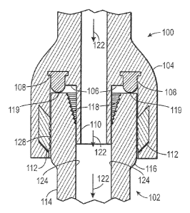
[0025] FIG. 3 is a schematic cross-sectional view of a gripping device 100
in the process
of being coupled with a drillpipe element 102 in accordance with embodiments
of the present
technique. In the illustrated embodiment, the gripping device 100 includes a
housing 104, a
coupling device or housing face 106, an integral seal 108, a filler neck 110,
and engagement
pads 112 (also known in the art as "slips"). The drillpipe element 102
includes a drillpipe
body 114, a tool joint 116, threads 118, and a drillpipe face 119.
[0026] Specifically, the arrangement of the gripping device 100 and the
drillpipe element
102 illustrated by FIG. 3 represents the gripping device 100 being set down on
the drillpipe
element 102 such that, as generally discussed above, pressure or force (e.g.,
the weight of a
top drive or pipe drive system) is applied to the integral seal 108 via the
gripping device 100
and the drillpipe element 102. This force or pressure causes deformation of
the integral seal
108 and establishment of a pressurized seal in a seal area between a flow path
122 through
the gripping device 100 and drillpipe element 102, and areas outside of the
flow path 122.
[0027] The flow path 122 includes the filler neck 110, which extends into
the drillpipe
element 102. While embodiments in accordance with the present techniques may
not include
such a feature, the illustrated embodiment includes the filler neck 110 to
direct fluid flow
past the threads 118 of the drillpipe element 102 and past the integral seal
108. Indeed, when
fully inserted, the filler neck 110 is of sufficient length to extend past the
integral seal 108
and past the threads 118 to limit interaction of circulation fluid with these
components.
Further, the filler neck 110 is sized such that it has limited clearance
between the walls of
the 124 drillpipe element 102, which creates resistance to back flow of the
fluid towards the
threads 118 and integral seal 108. The inclusion and sizing of the filler neck
110 will thus
9
CA 2861770 2018-01-02
resist degradation of features of the gripping device 100 and drillpipe
element 102 due to
washout and so forth.
[0028] In the illustrated embodiment, the engagement pads 112 have not yet
engaged
with the outer circumferential area of the drillpipe element 102. However,
once the
pressurized seal is established to a desired degree, the engagement pads 112
may be actuated
to radially engage an exterior of the drillpipe element 102. In some
embodiments, the
engagement pads 112 may be radially actuated by pushing them up or down with
respect to
an axis of the gripping device 100 such that they slide along a ramp that
presses the
engagement pads 112 radially inward to engage the drillpipe element 102. This
actuation
may be achieved in various manners, such as hydraulically or based on
frictional engagement
with the drillpipe element 102. For example, sliding the drillpipe element 102
between the
engagement pads 112 may cause the engagement pads 112 to slide upwards against
a ramp
that pushes the engagement pads 112 radially inward. In another embodiment,
the
engagement pads 112 may be pressed radially inward without any vertical
sliding motion.
Indeed, various different actuation techniques and engagement features may be
utilized in
accordance with present embodiments.
[0029] In the illustrated embodiment, patterns 128 on the surface of the
engagement pads
112 are configured to function as wickers and may be pressed into contact with
the outer
circumferential area of the tool joint 116 to establish a frictional coupling
between the
gripping device 100 and the drillpipe element 102. The patterns 128 may be
arranged to
provide resistance to movement in multiple directions once engaged. For
example, the
patterns 128 may include upwardly angled teeth and teeth aligned with an axis
of the
drillpipe element 102 such that rotational and lifting motions are efficiently
imparted to the
drillpipe from the gripping device 100. In this way, force from a top drive
coupled to the
gripping device 100 can be utilized to lift or rotate the drillpipe 102 during
an assembly or
disassembly process.
[0030] FIG. 4 is a schematic cross-sectional view of a gripping device 200
in the process
of being coupled with the drillpipe element 102 about a separate seal 202 in
accordance with
embodiments of the present technique. In the illustrated embodiment, the
gripping device
CA 2861770 2018-01-02
200 includes a housing 204, a coupling device or housing face 206, a seal
groove 208, a filler
neck 210, and engagement pads 212. As discussed above, the drillpipe element
102 includes
the drillpipe body 114, the tool joint 116, the threads 118, and the drillpipe
face 119.
[0031] Specifically, the arrangement of the gripping device 200 and the
drillpipe element
102 illustrated by FIG. 4 represents the gripping device 200 being set down on
the drillpipe
element 102 after the separate seal 202 has been positioned on the drillpipe
face 119. As
generally discussed above, once the separate seal 202 is abutting the housing
face 206 and
the drillpipe face 119 within a seal area, pressure or force (e.g., the weight
of a top drive or
pipe drive system) may be applied to cause deformation of the separate seal
202. Thus, the
separate seal 202 is utilized to establish a pressurized seal between a flow
path 222 through
the gripping device 200 and drillpipe element 102, and areas outside of the
flow path 222.
[0032] In the illustrated embodiment, the housing face 206 includes the
seal groove 208,
which is formed to provide a receptacle for the separate seal 202. In the
illustrated
embodiment, the separate seal 202 has been positioned on the drillpipe face
119 such that
when it engages with the housing face 206, the separate seal 202 will be
pressed into the seal
groove 208. In other situations, the separate seal 202 may be initially
installed within the
seal groove 208 before coupling the gripping device 202 with the drillpipe
element 102.
Including a receptacle such as the seal groove 208 may stabilize the separate
seal 202 and
provide additional seal integrity. However, in some embodiments, the housing
face 206 may
not include the seal groove 208 or any type of receptacle for the separate
seal 208. Rather,
in some embodiments, the housing face 206 may be substantially flat and/or
textured for
engagement with the separate seal 202 such that it can be pressed between the
housing face
206 and the drillpipe face 119.
[0033] Other aspects of the gripping device 200 illustrated in FIG. 4 are
similar to those
of the gripping device 100 illustrated in FIG. 3. For example, when the flow
path 222 is
established by coupling the gripping device 200 with the drillpipe element
102, the flow path
222 includes the filler neck 210, which extends into the drillpipe element
102. Further, as
with the embodiment illustrated in FIG. 3, the engagement pads 212 illustrated
in FIG. 4
have not yet engaged with the outer circumferential area of the drillpipe
element 102.
11
CA 2861770 2018-01-02
However, once the pressurized seal is established to a desired degree, the
engagement pads
112 may be actuated to radially engage an exterior of the drillpipe element
102 such that
patterns or vvickers 228 of the engagement pads 112 frictionally grip the
drillpipe element
102, or more specifically the tool joint 116 portion of the drill pipe element
102.
[0034] FIG. 5 is a process flow diagram of a method of assembling or
disassembling a
drill string in accordance with present techniques. The method is generally
indicated by
reference numeral 300 and includes blocks that are representative of various
steps or acts in
the method 300. It should be noted that the various steps of the method 300
can be performed
in the illustrated order or in a different order in accordance with present
techniques. Further,
in some instances, certain steps illustrated in FIG. 5 may be eliminated or
additional steps
may be performed.
[0035] As represented by block 302, the method 300 begins with extending a
housing of
a gripping device over a distal end of a drillpipe element such that a
boundary of the housing
extending from a perimeter of a face of the gripping device surrounds a
circumferential area
of the drillpipe element. As represented by block 304, this may result in
stabbing a filler
neck into the drillpipe element, wherein the filler neck extends from an inner
perimeter of
the face of the gripping device. Next, as represented by block 306, the method
300 includes
pressing a seal between the face of the gripping device and a face of the
drillpipe element.
The seal may be integral with the gripping device or this may include the act
of placing the
seal between the gripping device and the drillpipe element. Further, block 308
represents
engaging the circumferential area of the drillpipe element with an engagement
feature of the
gripping device. The step represented by block 308 may include hydraulically
actuating
gripping pads. Block 310 represents rotating the gripping device to impart
rotation to the
drillpipe element to facilitate attachment or detachment of the drillpipe
element with a drill
string. Further, block 312 represents passing fluid through the filler neck
into the drill string.
[0036] Present embodiments may provide the advantages of a relatively
simple, reliable,
and inexpensive seal between the surface equipment on the drilling rig and a
string of drill
pipe without the need to make-up a threaded connection. In one embodiment, the
seal could
be an elastomeric ring, such as urethane, nitrile or butyl rubber, that is
pressed between the
12
CA 2861770 2018-01-02
sealing surface within the gripping device and the upward facing surface of
the drill pipe.
The seal's pressure capability is substantially dependent, if not
proportional, to squeeze
applied to the seal. The weight of the gripping device and other surface
equipment, such as
the top drive, is typically over 20,000 lbs., if not several times that
weight. Most of the
surface equipment weight can be applied towards squeezing the seal, which
should easily
withstand fluid pressures typical of drilling operations. This simplified,
somewhat "brute
force," method of sealing allows for wide dimensional and surface finish
tolerances because
the squeezed seal will simply form itself to the surfaces between which the
seal is squeezed.
The ability to seal against surface imperfections is useful because the drill
pipe is handled
roughly during drilling operations, which leads to gouges and scratches on the
face of the
tool joint. Because the simple shapes (e.g., cylindrical or 0-ring) and
relatively cheap
elastomers that may be used for the seal, the seals may even be treated as
disposable without
adding significantly to the costs of the drilling operation.
[0037] While
only certain features of the invention have been illustrated and described
herein, many modifications and changes will occur to those skilled in the art.
It is, therefore,
to be understood that the appended claims are intended to cover all such
modifications and
changes as fall within the true spirit of the invention.
13
CA 2861770 2018-01-02