Note: Descriptions are shown in the official language in which they were submitted.
CA 02861844 2014-08-25
AXIAL ALIGNMENT APPARATUS AND METHOD
FOR MAINTAINING CONCENTRICITY BETWEEN
A SLOTTED TUBULAR AND A SEAMER HEAD
FIELD OF THE DISCLOSURE
The present disclosure relates in general to "seaming" methods and apparatus
for
reducing slot width in slotted tubular members such as wellbore liners, and
relates in
particular to apparatus for keeping a slotted tubular concentric with a seamer
head being
used to seam the slots in the slotted tubular.
BACKGROUND
Technological advances in directional drilling within the oil industry have
enabled
wells to be completed with long horizontal sections extending into subsurface
formations.
Such long horizontal wellbores, often more than 1,000 meters long, permit
fluids to be
injected into or produced from a more extensive portion of a subsurface
formation than
would be possible using vertical wells, with commensurately greater recovery
of
petroleum fluids than from vertical wells. The horizontal sections of such
wells are often
completed with slotted steel tubulars (altematively referred to as slotted
liners) that
function as screens or filters permitting flow of injected or produced fluids
across the
tubular wall while excluding the passage of solids.
For a slotted liner to function effectively as both a filter and a structural
member
in fine-grained reservoirs, and to be sufficiently rugged to endure
installation handling
loads, the slotted liner design is driven by three somewhat competing needs.
To ensure
adequate solid particle exclusion, the slot width must be on the order of the
smaller sand
grain sizes expected to be encountered in the formation. This is generally
true even where
fluids are injected out of the liner into the formation, because the effective
radial stress in
the sand tends to force sand grains into the well bore, even though fluids are
flowing out.
For reservoirs comprising very fine-grained material, slots narrower than 0.15
mm in
width may be required. However, small slot widths tend to increase flow loss;
therefore, a
larger number of slots are needed per unit of contacted reservoir area to
maintain flow
- 1-
:
-CA 02861844 2014-08-25
capacity, while the liner must accommodate the larger number of slots without
unacceptable loss of structural capacity.
The petroleum industry also recognises advantages, for production applications
in
particular, of slots that have a "keystone" shape in cross-section; i.e., with
the flow
channel through the wall of the tubular liner diverging (widening) from the
external entry
point to the internal exit point. This geometry reduces the tendency for sand
grains to
lodge or bridge in the slot, which could cause the slot to plug and restrict
flow.
The required or desired width of the slots in a slotted tubular liner is
commonly
less than the slot width that can be formed using conventional rotary saw
blades or other
slot-forming technologies. Therefore, it is commonly necessary or desirable to
narrow
the width of the slots in slotted liners after initial formation of the slots.
It is known to do
this by applying pressure at or along the edges of the slots to plastically
deform and
displace material adjacent to the slot edges to narrow the slot width. The
term
"seaming", as used in this patent document, is to be understood as denoting or
referring
to the process or method of narrowing the width of slots in a slotted tubular
liner by this
means (i.e., application of pressure to induce plastic deformation resulting
in reduction of
the slot width). Similarly, the terms "seamer" and "seamer head", as used in
this patent
document, refer to apparatus used for purposes of seaming.
U.S. Patent No. 6,898,957 (Slack), which is incorporated herein by reference
in its
entirety, teaches methods and apparatus for seaming slotted tubular liners. In
accordance
with certain embodiments taught by US 6,898,957, these methods and apparatus
provide
at least one rigid contoured forming tool with means for applying a
concentrated and
largely radial load against the inside or outside cylindrical surface of a
slotted metal
tubular liner. The radial load thus applied at a given location on the
contacted surface
creates a localized zone of concentrated stress within the tubular material,
which stress is
sufficient to cause a significant zone of plastic deformation when the contact
location is
near the edge of a slot. Means are also provided for simultaneously displacing
the
forming tool or tools with respect to the tubular along path lines creating a
typically
helical sweep pattern over the cylindrical surface of the tubular. The sweep
pattern is
-2-
___________________ -,
CA 02861844 2014-08-25
configured such that the extended zone of plastic deformation created as the
forming tool
passes each point on the path line covers an area sufficient to intersect the
edges of all
slots intended to be narrowed in width.
In accordance with methods taught in US 6,898,957, the paths followed by the
displacement of the forming tool or tools, as they follow the sweep pattern,
traverse the
edges of the slots a sufficient number of times and at sufficiently close
intervals while
maintaining sufficient contact force to plastically form the edges of all
slots intersected
along the slots' full lengths. The plastic deformation thus caused at the
edges of the slots
tends to narrow the width between opposing longitudinal edges of the slots in
the
contacted surface of the slotted metal tubular. Otherwise stated, the area
affected by the
extended zone of localized plastic flow, as the forming tool(s) move over the
inside or
outside surface of the slotted tubular liner, is sufficient to more than
completely cover the
edges of all slots to be narrowed by plastic deformation. The area swept by
the forming
tools need not be continuous over the entire surface of the slotted tubular
liner, but
optimally will include the area of influence from path lines occurring at at
least two
separate locations for each slot narrowed.
The steps in these methods firstly include providing a slotted tubular liner
in
which the slots:
= extend through the tubular wall;
= have longitudinal peripheral edges;
= are preferably of approximately equal length;
= typically have parallel slot walls (such as will result from cutting
slots with a
rotating saw blade); and
= are preferably arranged in rows of circumferentially-distributed slots,
with
adjacent rows of slots being separated by unslotted intervals or rings;
effectively forming a structure in which the material segments between slots
act as short
longitudinal beams spanning between unslotted intervals. Sub-lengths of the
tubular liner
having groups of one or more rows of slots are referred to as slotted
intervals.
- 3 -
- CA 02861844 2014-08-25 =
These methods also call for the steps of providing at least one and preferably
multiple contoured rigid forming tools, preferably in the form of contoured
rollers, and
applying pressure to a local area on the exterior surface of the tubular by
means of the
rigid contoured forming tools, beginning at one end of a slotted interval. At
the same
time, the forming tools are moved over the surface of the tubular in a tight
and preferably
helical sweep pattern, progressing along the length of the tubular so as to
cover each
slotted interval in turn. The contoured forming tool shape, the radial load
exerted by the
forming tools against the tubular surface, the pitch of the helical path, and
the number of
passes of the forming tools (i.e., the number of times the above-described
operation is
repeated) are all adjusted so as to result in sufficient deformation of the
edges of the slots
along their length to uniformly narrow each slot to a desired width.
The methods and apparatus taught in US 6,898,957 can also be used to narrow
the
width of slots in a slotted tubular as measured at the interior surface of the
tubular. This
is achieved by using steps substantially as described above for narrowing
slots at the
exterior surface, except that the rigid forming tools are configured to apply
pressure to
the interior surface of the slotted tubular. This causes the width of each
slot to be
narrowed along its interior edges creating an inverse keystone flow-channel
shape, which
shape is desirable for injection applications (i.e., where a fluid is being
injected outward
from the tubular into a surrounding subsurface formation).
As outlined in US 6,898,957, the geometry of the generally keystone channel
shape created by forming the edges of slots may be further characterized in
terms of the
rate at which the slot width increases with depth from the contacted surface
edges, i.e., its
divergence rate (or the angle of the slot wall). It will be generally
appreciated that slots
having a lower divergence rate can be expected to plug more easily than slots
with a
higher divergence rate for the same reason that the keystone shape is
preferred over
parallel wall slots. However, if the divergence rate is very high, the formed
edges will
have less material supporting them and therefore will be more susceptible to
material loss
through erosion or corrosion. In applications where this material loss causes
a significant
increase in slot width, the ability to screen to the desired particle size may
be
compromised.
-4-
-
- _ CA 02861844 2014-08-25 õ..
_
_
For this reason, US 6,898,957 also teaches methods for narrowing the width of
slots in slotted metal tubulars by both forming the slot edges as described
above and also
to control the slot divergence rate or depth to which the slot is narrowed.
These objectives
can be achieved by manipulating the forming tool shape according to criteria
set out in
US 6,898,957.
The methods and apparatus taught by US 6,898,957 have proven to be very
effective, and large quantities of slotted tubulars are seamed every year
using such
methods and apparatus. However, production efficiency using methods and
apparatus in
accordance with US 6,898,957 can be hampered by the common problem of tubulars
having a longitudinal bend or "bowing", typically resulting from factors such
as
differential cooling of longitudinal weldment areas during the manufacture of
the
tubulars. Such bends typically are not very dramatic, and not significant
enough to cause
problems with during installation or service when the tubulars are being used
to make up
drill strings or casing strings or as liners in horizontal wells. However,
even slight
longitudinal bowing can cause difficulties when present in a slotted tubular
being seamed
by a rotating seamer head of the type taught in US 6,898,957.
The seamer head in US 6,898,957 rotates about a rotational axis that is
effectively
fixed in space, given that the seamer head forms part of an apparatus that
typically is
stationary. In the ideal case, a length of slotted liner passing through the
seamer head
would be perfectly straight, such that its centroidal axis (i.e., centerline)
would coincide
with the rotational axis of the seamer head as it passes through the seamer
head. In that
idealized scenario, the pressures or forces exerted against the surface of the
slotted
tubular by all of the forming tools of the seamer head would be substantially
uniform,
thus promoting predictably uniform narrowing of the slots in the tubular.
However, if the centerline of the slotted liner deviates from concentricity
with the
rotational axis of the seamer due to an inherent longitudinal bend in the
tubular, the
pressures and forces exerted by the forming tools will vary, thus resulting in
undesirable
variations in slot width after seaming, or else entailing additional and
intermittent steps to
adjust the seaming equipment, or to adjust the means for supporting the non-
rotating liner
- 5 -
-CA 02861844 2014-08-25
as it passes through the seamer (or, in some embodiments, as the seamer moves
over the
liner), such that the liner centerline is kept generally coincident with the
rotational axis of
the seamer head to facilitate acceptable quality control with respect to
seamed slot width.
Although such adjustment steps may be helpful to address longitudinal bends in
slotted liners that need to be run through a rotating seamer head, they
decrease seaming
efficiency and increase the cost of producing accurately-seamed slotted
liners.
Restricting seaming operations to slotted tubular liners having perfectly
straight
centroidal axes would be impractical and unrealistic. For these reasons, there
is a need
for improvements to seaming methods and apparatus that will allow
longitudinally-
bowed slotted liners to be seamed as effectively and efficiently as unbowed
liners.
BRIEF SUMMARY
The present disclosure teaches axial alignment apparatus for aligning the
vertical
and horizontal position of the rotational axis of a seamer head with the
centerline of a
slotted tubular liner as the liner passes through the spindle bore of the
seamer head. This
is accomplished by providing liner centerline sensor means adapted to detect
the position
of the liner's centroidal axis (centerline). In illustrated embodiments, the
liner centerline
sensor means are provided in the form of liner position probes deployable to
physically
contact the exterior surface of the tubular in order determine the vertical
and horizontal
coordinates of the liner centerline. The illustrated embodiments of the axial
alignment
apparatus have two liner position probes for determining the vertical position
of the liner
and two liner position probes for determining the horizontal position of the
liner.
However, this is by way of example only; the number and angular orientation of
the liner
position probes could be different in alternative embodiments without
departing from the
scope of the present disclosure.
Although embodiments of axial alignment apparatus in accordance with the
present disclosure are described and illustrated herein as having liner
centerline sensor
means in the form of liner position probes that physically contact the liner,
this is by way
of non-limiting example only. In alternative embodiments, the liner centerline
sensor
- 6 -
_ .. CA 02861844 2014-08-25
means could use optical means (such as lasers) or other means adapted or
adaptable to
sense the liner's spatial position without entailing physical contact with the
liner.
In illustrated embodiments, the liner centerline sensors are mounted on or
closely
adjacent to the seamer head. In variant embodiments, however, the liner
centerline
sensor may be displaced in an axial direction away from the seamer head, with
the axial
alignment apparatus's control means (described later herein) being programmed
or
calibrated or otherwise adapted to translate readings from the displaced liner
centerline
sensors to provide sufficiently accurate determinations of the liner
centerline's position at
the spindle bore of the seamer head.
In accordance with methods taught herein, a slotted tubular liner is presented
to
the spindle bore of a seamer head by means of external apparatus that supports
the liner
such that the seamer head rotates relative to the liner, and the liner moves
axially relative
to the seamer head. The seamer head defines a rotational axis, which is the
intended axis
of relative rotation as between the seamer head and the liner when the
centerline of the
liner is coincident with the rotational axis. In some embodiments the seamer
head may
rotate about the rotational axis while the liner is non-rotating; in other
embodiments the
seamer head may be non-rotating while the tubing rotates. In some embodiments
the
relative axial movement as between the seamer head and the liner may be
effected by
axially moving the seamer head relative to an axially-stationary liner; in
other
embodiments the liner may be moved axially relative to an axially-stationary
seamer
head.
Other embodiments may provide for rotation of both the seamer head and the
liner, but at different rotational speeds, such that there is still relative
rotation as between
the seamer head and the liner. Similarly, alternative embodiments may provide
for axial
movement of both the seamer head and the liner, either in opposite directions
or in the
same direction but at different speeds, such that there is still relative
axial movement as
between the seamer head and the liner.
Once the liner is supported on both sides of the seamer head by the external
apparatus, the liner position probes can move into position against the
cylindrical surface
- 7 -
CA 02861844 2014-08-25
of the liner. Persons skilled in the art will appreciate that this can be done
in a variety of
ways in accordance with known technologies, and axial alignment apparatus
within the
scope of the present disclosure is not intended to be limited or restricted to
the use of any
particular means for positioning the liner position probes. By way of non-
limiting
example, however, in embodiments illustrated herein, the liner position probes
are
actuated by respective positioning motors and linear drive assemblies in
conjunction with
linear rails. Each positioning motor will place a corresponding spring-loaded
follower
wheel into contact with the liner, and will preload the follower wheel's
spring-loaded
guide assembly to a pre-determined position based upon the diameter of the
liner (the
cross-sectional perimeter of which is assumed to be circular, rather than
having any out-
of-roundness). The position of each spring-loaded follower wheel is then
measured by a
corresponding linear encoder. This process is carried out simultaneously and
continuously with respect to all four probes as the liner moves through the
seamer head
spindle bore.
The apparatus incorporates a programmable logic controller (PLC) programmed
to position the seamer head so as to be concentric with the liner at all
times, by means of
horizontal and vertical axis positioners. Once all four position probes have
been
positioned against the liner, the PLC will evaluate the position of each
spring-loaded
follower wheel by means of its associated linear encoder to determine the
position of the
rotational axis relative to the liner's centerline. If the rotational axis is
coincident with the
liner's centerline, no further action is taken. If the rotational axis is not
coincident with
the liner's centerline, the PLC will instruct either the vertical axis
positioner or the
horizontal axis positioner, or both, to move the seamer head either
horizontally or
vertically, or both, as necessary to make the rotational axis substantially
coincident with
the liner's centerline as the liner passes through the spindle bore of the
seamer head. The
PLC continuously polls all linear encoders at sufficiently frequent intervals
to ensure that
the rotational axis remains at least substantially coincident with the liner's
centerline at
all times as the liner moves through the seamer head.
Accordingly, in one aspect the present disclosure teaches an apparatus for
aligning the rotational axis of a seamer head with the centerline of a tubular
member
- 8 -
02861844 2014-08-25
disposed within a spindle bore of the seamer head parallel to the rotational
axis, wherein
the apparatus comprises:
= positioning means, for adjusting the spatial position of the seamer head
in a
direction transverse to the rotational axis;
= centerline sensor
means, for sensing the spatial position of the tubular member's
centerline where the tubular member passes through the spindle bore; and
= control means adapted to receive centerline position data from the
centerline
sensor means, to determine the spatial position of the tubular member's
centerline
based on received centerline position data, to compare the spatial position of
the
tubular member's centerline relative to the seamer head's rotational axis, and
to
actuate the positioning means as necessary to move the seamer head in a
direction
transverse to the seamer head's rotational axis so as to bring the rotational
axis
into substantial concentricity with the tubular member's centerline at the
location
of the seamer head.
In a second aspect the present disclosure teaches an axial alignment apparatus
comprising:
= a base structure;
= a seamer head frame mounted to and horizontally movable relative to the
base
structure;
= a seamer head carrier mounted to and vertically movable relative to the
seamer
head frame;
= a seamer head mounted to the seamer head carrier, with the seamer head
defining
a rotational axis and further having a spindle bore for receiving a tubular
liner
oriented with its centerline parallel to the rotational axis;
= horizontal positioning means, for adjusting the horizontal position of the
seamer
head frame relative to the base structure;
= vertical positioning means, for adjusting the vertical position of the
seamer head
carrier relative to the seamer head frame;
-9-
-
= a plurality of liner centerline measurement probes mounted in association
with the
seamer head carrier and adapted for contacting engagement with the cylindrical
exterior surface of a tubular liner disposed within the spindle bore of the
seamer
head;
= rotation means,
for providing relative rotation about the rotational axis as between
the tubular liner and the seamer head;
= axial movement means, for providing relative axial movement as between
the
tubular liner and the seamer head;
= a plurality of linear encoders, each linear encoder being associated with
one of the
centerline measurement probes and being adapted to measure the spatial
position
of its associated centerline measurement probe when the probe is in contact
with
the exterior surface of the liner; and
= control means programmed to poll the linear encoders to determine the
spatial
positions of their associated centerline measurement probes, to calculate the
spatial position of the liner centerline based on data polled from the
encoders, to
compare the spatial position of the liner centerline relative to the
rotational axis,
and to actuate one or more of the horizontal and vertical positioning means to
move the seamer head as necessary to bring the rotational axis into
substantial
concentricity with the liner centerline.
In a first embodiment, the rotation means is adapted to rotate the seamer head
about the rotational axis, and the axial movement means is adapted to move a
tubular
liner axially through the spindle bore of the seamer head.
In a second embodiment, the rotation means is adapted to rotate the seamer
head
about the rotational axis, and the axial movement means is adapted to move the
seamer
head axially relative to a tubular liner disposed within the spindle bore of
the seamer
head.
In a third embodiment, the axial movement means is adapted to move a tubular
liner axially through the spindle bore of the seamer head, and the rotation
means is
adapted to rotate the tubular liner.
- 10-
CA 02861844 2014-08-25
In a fourth embodiment, the axial movement means is adapted to move the seamer
head axially relative to a tubular liner disposed within the spindle bore of
the seamer
head, and the rotation means is adapted to rotate the tubular liner.
The control means may comprise a programmable logic controller (PLC) or any
other functionally suitable programmable control device.
In a third aspect, the present disclosure teaches a method for maintaining
axial
alignment between a tubular liner and a seamer head through which the tubular
liner is
passing. This method includes the steps of:
= providing a seamer head defining a spindle bore and a rotational axis;
= disposing a tubular liner within the spindle bore, with the centerline of
the liner
parallel to the rotational axis;
= determining the spatial position of the liner centerline relative to the
spatial
position of the rotational axis; and
= re-positioning the seamer head as necessary to bring the rotational axis
into
substantial concentricity with the liner centerline.
BRIEF DESCRIPTION OF THE DRAWINGS
Embodiments of apparatus and methods in accordance with the present disclosure
will now be described with reference to the accompanying figures, in which
numerical
references denote like parts, and in which:
FIGURE 1 illustrates a slotted tubular liner having circumferentially-
arrayed rows of longitudinal slots.
FIGURE 1A is a cross-section through the slotted liner in FIG. 1.
FIGURE 2 illustrates slots in a slotted liner as in FIG. 1 being seamed by
a prior art forming roller as taught in US 6,898,957.
FIGURE 2A is a cross-section through the slotted liner and forming roller
in FIG. 2.
- 11 -
FIGURE 3 is an elevational view of a prior art seamer head as taught in
US 6,898,957, carrying three forming rollers shown in contact with a
slotted liner passing through the seamer head.
FIGURE 4 illustrates one embodiment of a prior art seaming apparatus as
taught in US 6,898,957 having a stationary rotating seamer head, with a
non-rotating slotted liner passing longitudinally through the seamer head.
FIGURE 5 illustrates geometrical parameters of an exemplary prior art
forming roller as taught in US 6,898,957.
FIGURE 6 is a plan view of a longitudinal slot that has been transversely
seamed by a forming roller as taught in US 6,898,957, illustrating the areal
extent of zones adjacent to the slot subject to plastic deformation due to
forces exerted by the forming roller.
FIGURE 7 is a cross-sectional detail through a slot through the wall of a
slotted liner as in FIG. 6, illustrating the shape of the slot after
transverse
seaming.
FIGURE 8 is a first isometric view of a seamer head mounted in
association with one embodiment of an axial alignment apparatus in
accordance with the present disclosure.
FIGURE 9 is a second isometric view of the seamer head and axial
alignment apparatus shown in FIG. 8.
FIGURE 10 is an isometric view of one embodiment of a liner position
probe suitable for use in the axial alignment apparatus shown in FIGS. 8
and 9.
FIGURE 11 is an isometric detail of the spring-mounted follower of the
liner position probe shown in FIG. 10.
FIGURE 12A is an elevation showing a slotted tubular liner positioned in
association with the axial alignment apparatus shown in FIGS. 8 and 9,
with the centreline of the slotted liner being both laterally and vertically
offset from the rotational axis of the seamer head.
- 12-
02861844 20140825. ,....
FIGURE 12B is an elevation similar to FIG. 12A, but after the vertical
axis positioners have repositioned the seamer head such that the vertical
position of the seamer head's rotational axis corresponds to the vertical
position of the centerline of the slotted liner.
FIGURE 12C is an elevation similar to FIG. 12B, but after the horizontal
axis positioners have repositioned the seamer head such that the lateral
position of the seamer head's rotational axis corresponds to the lateral
position of the centerline of the slotted liner, such that the seamer head's
rotational axis and the centerline of the slotted liner are substantially
coincident as the liner passes through the seamer head.
FIGURE 12D is an elevation similar to FIG. 12C, but with all seaming
rollers in contact with the outer surface of the slotted liner.
DESCRIPTION
Prior Art Seaming Apparatus
To promote optimal and comprehensive understanding of axial alignment
apparatus in accordance with the present teachings, the physical structure and
operation
of a prior art seaming apparatus as disclosed in US 6,898,957 will be
described below,
having reference to FIGS. 1-7. It is to be understood, however, that
notwithstanding the
description and illustration provided herein with respect to US 6,898,957,
axial alignment
apparatus and methods in accordance with the present disclosure are not in any
way
limited or restricted to use in association with seaming apparatus and methods
as taught
in US 6,898,957.
In accordance with US 6,898,957, and as illustrated in FIGS. 1 and 1A, a
slotted
tubular liner 1 has an exterior surface 2, an interior surface 3, and one or
more
longitudinal slots 4, each having exterior longitudinal peripheral edges 5 and
6 as
illustrated in FIG. 1. To reduce the width between exterior peripheral edges 5
and 6 of
slots 4, a contoured rigid forming tool, typically configured in the form of a
forming
roller (alternatively referred to as a seaming roller) 7, is forced into
contact with the
- 13 -
.. 02861844 2014-08-25
exterior surface 2 of slotted liner 1 to apply localized pressure while being
moved largely
transversely with respect to liner 1 along a helical path 8 as shown in FIGS.
2 and 2A.
Sufficient contact pressure is applied to liner 1 through forming roller 7 to
plastically
deform peripheral edges 5 and 6 of slots 4 as roller 7 traverses slots 4
following a helical
path 8. The pitch 9 and total length of helical path 8 are adjusted to ensure
that the
localized zones of plastic deformation created as roller 7 sequentially
traverses a given
slot 4 occur at close enough intervals to effectively continuously deform the
slot along its
entire length.
FIG. 2 illustrates the forming process at an intermediate step where the slot
width
at peripheral edges 5 and 6 of slots 4 already traversed by forming roller 7
following
helical path 8 has been narrowed.
Having regard to the teachings of US 6,898,957, it will be apparent to persons
skilled in the art that for a given slotted tubular liner, there will be
relationships between
the reduction in slot width and:
= the radial force applied to the forming roller;
= the shape of the forming roller;
= the pitch of the helical fortning path;
= the number of times the roller traverse is repeated; and
= to a limited extent, the speed at which the roller is moved relative to
the liner
surface.
The manner in which these variables interact may be generally understood as
follows:
= The greater the available force, the greater the amount of plastic
deformation
possible.
= For a given available force, the shape of the forming roller generally
controls the
magnitude and longitudinal extent over which the reduction in slot width
occurs
for a single traverse of the roller over a slot.
- 14-
CA 02861844 2014-08-25 .
The pitch of the helical forming path should be co-ordinated with the axial
extent
over which the reduction in slot width occurs for a single traverse of the
roller
over a slot, to ensure that the width reduction occurs over the entire
longitudinal
extent of the slot.
= Repeated traverses of the roller over the same slot location at the same
load tend
to increase the amount of deformation by incrementally smaller amounts as the
number of traverses is increased.
The maximum radial force which may be applied to the forming roller is a
function of the manner in which the slotted liner is supported and, therefore,
how the
force applied through the roller is reacted. It will be evident that there
exist numerous
means of supporting the liner and reacting the radial force applied through a
forming
roller 7, including providing support on the inside of the liner. However, it
is most
convenient if fixturing acting primarily on the exterior surface 2 can support
the liner and
is arranged to react the radial force applied through a forming roller to the
liner through
one or more opposing radial rollers acting at or near the same axial plane.
The rollers
most conveniently apply these opposing radial forces when mounted in a common
rigid
frame, similar to the manner of a "steady rest" commonly used to support a
long work
piece in a lathe. It will be evident that two or more rollers can be arranged
to act as
forming rollers, in which case interleaved "multiple start" helical paths can
be generated
as a function of the liner rotation with respect to the rollers with
associated benefits in
production rate.
One such configuration is shown in FIG. 3. As illustrated in FIG. 3, the axles
10
of three radially-opposed forming rollers 7 are attached to the pistons 11 of
three
hydraulic actuators 12, each positioned at approximately 120 degrees around
liner 1 and
fastened to the forming head frame 13. Load is applied to the forming rollers
7 by
application of fluid pressure (conceptually denoted in FIG. 3 by reference
number 14).
Together this assembly is referred to as a forming head (alternatively
referred to as a
seamer head) 15. This configuration substantially reduces the tendency of the
liner to
bend and provides a radial load capacity enabling a reasonably large formed
zone without
permanent distortion of the liner's cross-sectional shape for typical slotted
liner materials.
-15-
-
- CA 02861844 2014-08-25 , õ,
-
The means by which one or more forming rollers 7 carried in seamer head 15 is
caused to move in a helical path 8, with respect to liner 1, may be
accomplished in
various ways. As a first example, liner 1 may be rotated while the forming
head is moved
axially in synchronism with the rotational position, in the manner of a lathe
used for
threading or turning operations. As a second example, the forming head may be
rotated
while liner 1 is moved axially through the head without rotation, in
synchronism with the
forming roller rotation. Other alternative architectures are described in US
6,898,957.
In one embodiment, seaming apparatus in accordance with US 6,898,95'7 employs
the above-noted second example of these architectures in a machine illustrated
in FIG. 4.
As shown in FIG. 4, the slotted liner 1 is positioned with respect to forming
head 15 by
guide rollers 16 and one or more drive rollers 17. Force applied by hydraulic
actuators 18
ensures that liner 1 is held in place, while drive roller 17 develops
sufficient friction to
axially displace liner 1 relative to the forming head 15 (as denoted by the
directional
arrow in FIG. 4) while forming head 15 is rotating. Forming head 15 is mounted
in
bearings 19 allowing it to be rotated by means of a drive belt 20 (or a drive
chain, gear
arrangement, or other suitable means) driven by a motor 21. The combination of
axial
and rotational motions thus provided causes forming rollers 7 to follow a
helical path 8
along the outside surface of liner 1 as shown in FIG. 2, with the pitch 9 of
helical path 8
being controlled by adjusting the axial feed rate with respect to the
rotational speed of
forming head 15.
The shape of the forming tool may be used in combination with the other
process
control variables such as load, pitch, and number of roller traverses to
adjust the amount
by which a slot is narrowed and the depth over which the slot narrowing
occurs. The
means by which roller shape controls these outcomes may be generally
characterized in
terms of the roller radius 22(R) and profile radius 23(c) as illustrated in
FIG. 5. While the
profile shape may take various forms, a simple convex shape, as shown in FIG.
5, has
been found to provide satisfactory control of slot width reduction when
forming
longitudinal slots following a largely transverse helical path.
- 16 -
_ CA 02861844 2014-08-25
To understand how these geometric parameters may be advantageously
manipulated, consider the shape of the zone of plasticity caused as a roller
7, having a
generally smooth convex profile shape, crosses the center of a slot 4
following a largely
transverse path. As shown in FIG. 6, the width of the areal extent of plastic
deformation
24 as a function of position along the roller path 25, caused when the roller
traverses the
slot, tends to be greatest nearest the slot. This occurs because the stressed
material is least
confined at the slot and creates an effective formed length 26(z) for a single
traverse of
forming roller 7 over a slot. Correspondingly, the depth of plastic
deformation is greatest
at the slot, producing narrowing of the through-wall channel shape to a
forming depth
27(d) as shown in FIG. 7. It will be apparent that if the pitch exceeds formed
length
26(z), the areal extent of successive roller traverses will not overlap
sufficiently along the
slot edges to effectively continuously narrow the slots over their entire
length, and the
slot is said to be under-formed.
Within the context of the preferred embodiment, there is a maximum allowable
roller load (F) dependent on the structural capacity of liner 1 when loaded by
the forming
rollers within the forming head. Furthermore, the amount by which the slot
width is to be
narrowed (AW) may be treated as a given for purposes of understanding the
choice of
forming roller radius 22(R) and profile radius 23(c). To maximize production
rate, it is
preferable to produce the required reduction in slot width by only rolling the
surface of
liner 1 once, with the roller load at or near the maximum allowable value (F).
Under these
assumptions, then, for a given roller radius 22(R), there is a minimum profile
radius
23(c), referred to as the critical radius, for which the desired AW is
obtained for a single
traverse of the slot, as illustrated in FIG. 6, with a corresponding value of
formed length
26(z). For these "optimum" conditions, the pitch must largely correspond to
formed
length 26(z) to avoid either under-forming or over-forming the slot. Pitch (P)
may
therefore be treated as a dependent variable. Such a minimum profile radius is
also
optimized to form the edges most completely to the ends of the slots.
Next consider the effect of variations in roller radius 22(R) assuming that
profile
radius 23(c) is "optimally" selected as described above. It will be apparent
that as 22(R)
is decreased, the extent of the zone of stress under the roller is reduced in
the direction of
- 17 -
. CA 02861844 2014-08-25
rolling (typically normal or perpendicular to the slot direction); therefore,
radius 23(c)
must be increased to maintain the condition of constant AW and formed length
26 (z) will
correspondingly increase. Because pitch increases with formed length 26(z),
the rate of
production increases for decreasing roller radius 22 (R). It should also be
apparent that
the forming depth 27(d) will decrease as roller radius 22(R) is decreased due
to the
reduced extent of the zone of stress under the roller, normal to the slot
direction. This
provides a means to control the shape of the formed edges concurrent with the
rate of
divergence in the flow channel.
However, it is preferable if the profile radius 23(c) is somewhat greater than
the
critical value, as this allows greater flexibility in accommodating randomness
in the
numerous variables (such as material properties) that affect slot width. The
greater
flexibility derives from the fact that as radius 23(c) becomes greater than
the critical
value, the pitch must on average be reduced to keep AW constant. Therefore, if
variations
in parameters (such as a decrease in strength) necessitate less forming, the
pitch may be
increased to compensate without causing under-forming. This ability to use
variation in
pitch to provide fine control of the final slot width is of practical benefit
for automating
the seaming process. In particular, if the slot width is measured directly
after the slots are
formed, variations from the desired width may be compensated for subsequent
formed
intervals by adjusting either the load or pitch but preferably the pitch. This
feedback task
may be performed manually or automated using a suitable means to measure slot
width.
Therefore, in preferred embodiments, the roller and profile radii are selected
to
ensure that adequate sensitivity of slot width to pitch is maintained to
facilitate process
control without compromising the ability of the roller to form the edges of
slots near their
ends.
- 18 -
CA 02861844 2014-08-25
Axial Alignment Apparatus
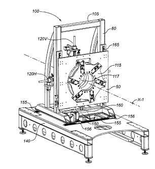
FIGS. 8, 9, and 12A-12D illustrate an axial alignment apparatus 100 for
keeping a
slotted tubular liner 101 concentric with a rotating seamer head 115 as seamer
head 115
narrows the width of the slots in slotted liner 101, by adjusting the vertical
and horizontal
positions of seamer head 115 as liner 101 passes through the spindle bore 117
of seamer
head 115. This is accomplished by means of liner centerline sensor means
provided, in
the illustrated embodiment, in the form of a plurality of liner position
probes 120H (for
horizontal position sensing) and 120V (for vertical position sensing) that
engage the
exterior surface of the liner to determine the vertical and horizontal
position of the liner's
centroidal axis (or centerline) CL.
In the illustrated embodiment, seamer head 115 is mounted to a seamer head
carrier structure 50 so as to be rotatable relative to seamer head carrier 50
about a
horizontal rotational axis X-1. Seamer head carrier 50 is mounted to a seamer
head frame
60 such that the vertical position of seamer head carrier 50 relative to
seamer head frame
60 is adjustable. This functionality may be provided (by way of non-limiting
example)
by providing vertical slide rails or tracks 165 on seamer head frame 60 as
shown in
FIG. 9, with seamer head carrier 50 being adapted to slidingly or rollingly
engage vertical
slide rails or tracks 165 (by suitable slide rail/track engagement means).
Seamer head frame 60 is mounted to a base structure 140 such that the
horizontal
position of seamer head frame 60 relative to base structure 140 (in a
direction transverse
to rotational axis X-1) is adjustable. This functionality may be provided (by
way of non-
limiting example) by providing horizontal slide rails 155 on base structure
140 as shown
in FIGS. 8 and 9, with seamer head frame 60 being adapted to slidingly or
rollingly
engage horizontal slide rails or tracks 155 (by suitable slide rail/track
engagement means
indicated by reference number 156).
In the illustrated embodiment, alignment apparatus 100 incorporates two
diametrically-opposed vertical liner position probes 120V and two
diametrically-opposed
horizontal liner position probes 120H. However, this is by way of example
only; the
- 19 -
CA 02861844
number and angular orientation of the liner position probes could be different
in
alternative embodiments.
In accordance with methods disclosed herein, a slotted liner 101 is presented
to
the seamer head spindle bore 117 by means of an external apparatus (not shown)
that
holds liner 101 in a vertically and horizontally stationary position while
allowing axial
movement of liner 101 relative to seamer head 115. Once liner 101 is supported
on both
sides of seamer head 115 by the external apparatus, the liner position probes
120H, 120V
can move into position.
Referring now to FIGS. 10 and 1 1_, the liner position probes 120H, 120V are
actuated by respective positioning motors 122 and linear drive assemblies 124
in
conjunction with linear rails. Each positioning motor 122 will place a
corresponding
spring-loaded follower wheel 126 into contact with slotted liner 101, and will
preload the
follower wheel's spring-loaded guide assembly 128 to a pre-determined position
based
upon the diameter of liner 101 (the cross-sectional perimeter of which is
assumed to be
circular, rather than incorporating ovality). The position of each spring-
loaded follower
wheel 126 is then measured by a corresponding linear encoder 130. This process
is
carried out simultaneously and continuously with respect to all liner position
probes as
liner 101 moves through seamer head spindle bore 117.
Referring back to FIG. 9, apparatus 100 incorporates a programmable logic
controller, or PLC (not shown), programmed to position seamer head 115 so as
to be
concentric with slotted liner 101 at all times, by means of one or more
horizontal axis
positioners 150 and one or more vertical axis positioners 160. Once all four
liner position
probes 12011, 120V have been positioned, the PLC will evaluate the position of
each
spring-loaded follower wheel 126 by means of its associated linear encoder 130
to
determine the position of seamer head 115 relative to centerline CL of liner
101. If the
rotational axis X-1 of seamer head 115 is coincident with centerline CL of
liner 101, no
further action is taken. However, if rotational axis X-1 is not coincident
with centerline
CL, the PLC will instruct either vertical axis positioner 160 or horizontal
axis positioner
150, or both, to move seamer head 115 either vertically or horizontally, or
both, as
- 20 -
CA 02861844 2014-08-25 ,...
necessary to make rotational axis X-1 substantially coincident with liner
centerline CL as
liner 101 passes through spindle bore 117 of seamer head 115. The PLC
continuously
polls all linear encoders 130 at sufficiently frequent intervals to ensure
that rotational axis
X-1 of seamer head 115 remains substantially coincident with liner centerline
CL as liner
101 passes through spindle bore 117.
Persons skilled in the art will appreciate that the function of horizontal
axis
positioner 150 and vertical axis positioner 160 may be provided by a variety
of means in
accordance with known technology. By way of non-limiting example, the axis
positioners
may comprise hydraulic cylinders, pneumatic cylinders, or geared mechanisms
(such as
rack-and-pinion arrangements). However, embodiments of axial alignment
apparatus
coming within the intended scope of the present disclosure are not limited to
the use of
any particular axis positioning means, including any of the above-noted
examples of axis
positioning means.
The operation of axial alignment apparatus 100 may be best understood with
reference to FIGS. 12A, 12B, 12C, and 12D, which sequentially illustrate how
apparatus
100 functions when the centerline of a slotted liner 101 positioned in spindle
bore 117 is
offset from the rotational axis of seamer head 115.
In FIG. 12A, liner centerline CL is shown offset both vertically and
horizontally
from rotational axis X-1 of seamer head 115.
In FIG. 12B, the one or more vertical axis positioners 160 have repositioned
seamer head carrier 50 (and seamer head 115 in turn), such that the vertical
position of
rotational axis X-1 corresponds to the vertical position of liner centerline
CL.
In FIG. 12C, the one or more horizontal axis positioners 150 have repositioned
seamer head carrier 50 (and seamer head 115 in turn) such that the lateral
position of
rotational axis X-1 also corresponds to the lateral position of liner
centerline CL. In
other words, the horizontal and vertical axis positioners 150 and 160, in
response to
control signals from the PLC based on data from centerline probes 120H and
120V, have
repositioned seamer head 115 to accommodate longitudinal bowing in slotted
liner 101,
- 21 -
CA 02861844 2014-08-25 , ..
such that rotational axis X-1 of seamer head 115 and liner centerline CL are
substantially
coincident as liner 101 passes through spindle bore 117 of seamer head 115. As
a result,
all seaming rollers 40 associated with seamer head 115 are now radially
equidistant from
liner 101, facilitating the application of equal radial forces by seaming
rollers 40 against
the outer surface of liner 101.
Although FIGS. 12A-12C show the positional adjustment of seamer head 115 as
separate sequential steps each making comparatively large adjustments, this is
for
illustrative purposes only. FIGS. 12A-12C illustrate an initial set-up phase
for axial
alignment apparatus 100. In actual operation, apparatus 100 will be
continually making
positional adjustments in response to the detection of any offsets between
rotational axis
X-1 and liner centerline CL as slotted liner 101 passes through seamer head
115. This
may be appreciated with reference to FIG. 12D, which is similar to FIG. 12C
except that
all seaming rollers 40 are now in contact with the cylindrical outer surface
of slotted liner
101. All such positional adjustments will tend to be small after initial start-
up of the
apparatus, as the apparatus reacts to frequent control inputs from the PLC,
such that
rotational axis X-1 and liner centerline CL will remain substantially
coincident as liner
101 passes through seamer head 115. Positional adjustments made by apparatus
100
typically will be made with the seaming rollers 40 in operative contact with
liner 101,
such the alignment process and the seaming process are carried out in concert
with each
other.
It is to be understood that the scope of the claims appended hereto should not
be
limited by the preferred embodiments described and illustrated herein, but
should be
given the broadest interpretation consistent with the description as a whole.
It is also to
be understood that the substitution of a variant of a claimed element or
feature, without
any substantial resultant change in functionality, will not constitute a
departure from the
scope of the disclosure.
- 22 -
, CA 02861844 2014-08-25
In this patent document, any form of the word "comprise" is to be understood
in
its non-limiting sense to mean that any element following such word is
included, but
elements not specifically mentioned are not excluded. A reference to an
element by the
indefinite article "a" does not exclude the possibility that more than one of
the element is
present, unless the context clearly requires that there be one and only one
such element.
Any use of any form of the terms "connect'', "engage", "couple", "attach",
"mount", or any other term describing an interaction between elements is not
meant to
limit the interaction to direct interaction between the subject elements, and
may also
include indirect interaction between the elements such as through secondary or
intermediary structure. Relational or relative terms (including but not
limited to
"horizontal", "vertical", "parallel", "perpendicular", "concentric", and
"coincident") are
not intended to denote or require absolute mathematical or geometrical
precision.
Accordingly, such terms are to be understood as denoting or requiring
substantial
precision only (e.g., "substantially horizontal") unless the context clearly
requires
otherwise.
Wherever used in this document, the terms "typical" and "typically" are to be
interpreted in the sense of representative or common usage or practice, and
are not to be
understood as implying invariability or essentiality.
- 23 -