Note: Descriptions are shown in the official language in which they were submitted.
CA 02862308 2016-01-19
PRESSURE ACTUATION ENABLING METHOD
BACKGROUND
[0001] It is common in tubular systems to actuate an actuator using pressure.
Doing
so often requires plugging a passageway so that pressure can be built
thereagainst. In cases
wherein it is desirable to flow through the passageway after having built
pressure against a
plug engaged therewith the plug must be removed. Methods such as drilling or
milling to
remove a rurmable plug work well for some applications. However, the time to
run the
drilling/milling equipment and perform the machining operation can be costly
in lost
production in the case where the tubular system is employed to recover
hydrocarbons from
an earth formation, for example. The art is therefore always interested in
methods of
allowing actuation without the aforementioned drawback.
BRIEF DESCRIPTION
[0002] Disclosed herein is a pressure actuation enabling method which includes
plugging a passage that fluidically connects an inside with an outside of a
tubular with a
plug, building differential pressure across the plug, actuating an actuator
with the
differential pressure and removing the plug.
[0003] Further disclosed herein is a pressure actuation enabling method
comprising:
plugging an annular passage defined radially between a first tubular
positioned radially of a
second tubular that fluidically connects an inside of the first tubular with
an outside of the
second tubular with a plug positioned within the annular passage; building
differential
pressure within the annular passage across the plug; actuating an actuator
with the
differential pressure, the actuating exposing the plug to an environment
dissolvable thereof;
and removing the plug.
BRIEF DESCRIPTION OF THE DRAWINGS
[0004] The following descriptions should not be considered limiting in any
way.
With reference to the accompanying drawings, like elements are numbered alike:
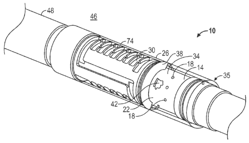
[0005] FIG. 1 depicts a partially transparent perspective view of a tubular
arrangement configured to enable pressure actuation of an actuator; and
[0006] FIG. 2 depicts a partial cross sectional side view of an embodiment of
a
tubular arrangement disclosed herein.
1
CA 02862308 2016-01-19
DETAILED DESCRIPTION
[0007] A detailed description of one or more embodiments of the disclosed
apparatus and method are presented herein by way of exemplification and not
limitation
with reference to the Figures.
[0008] Referring to Figure 1 a tubular arrangement configured to enable
pressure
actuation of an actuator is illustrated at 10. The tubular arrangement 10
includes a base pipe
14 with perforations 18 through a wall 22 thereof and a sleeve 26 positioned
radially of the
base pipe 14 defining a passageway 30 in the annular space 34 therebetween.
Fluidic
communication is established between an inside 42 and an outside 46 through at
least the
annular space 34 and the perforations 18. Additional flow channels, such as a
screen 48 and
an equalizer 74, as shown in this embodiment, may also be included in the
passageway 30.
The sleeve 26 is sealingly attached to the base pipe 14 at an end 35. A plug
38 occludes the
passageway 30 thereby preventing fluidic communication between the inside 42
and the
outside 46 of the tubular arrangement 10. The plug 38 is configured to support
differential
pressure between the inside 42 and the outside 46. The differential pressure
may be
sufficient to actuate an actuator (item 58 of Figure 2). For example, the
differential pressure
could inflate a bladder of an inflatable packer or move a piston 62 (Figure
2), such as the
packer and the piston disclosed in U.S. Patent 7,621 ,322 to Arnold et al.
[0009] The plug 38 is also configured to dissolve after being exposed to an
environment, after which fluid communication between the inside 42 and the
outside 46 is
established via the passageway 30. Such fluid communication prevents further
building
pressure differential between the inside 42 and the outside 46. The plug 38
may be made of
a high strength controlled electrolytic metallic material that is
degradable/dissolvable in
environments that include one or more of brine, acid, and aqueous fluid. For
example, a
variety of suitable materials and their methods of manufacture are described
in United States
Patent Publication No. 2011/0135953 to Xu etal. Exposing the plug 38 to the
degradable
environment can be controlled in different ways. For example, fluid containing
the
aforementioned brine, acid or aqueous fluid can be introduced via pumping
through the base
pipe 14 and the perforations 18 to the plug 38.
[0010] Referring to Figure 2, alternately, the brine, acid or aqueous fluid 50
can be
stored near the plug 38 in a chamber 54, for example, and then allowed to
access the plug 38
after actuation of an actuator 58. The actuator 58 illustrated in this
embodiment includes the
CA 02862308 2014-07-22
WO 2013/115923 PCT/US2012/071741
piston 62 sealably engaged with both the tubulars 14 and 26 by seals 64
thereby defining the
chamber 54. A releasable member 66, illustrated herein as a shear screw, fixes
the piston 62
relative to the tubulars 14, 26 until pressure acting on the piston 62 is
sufficient to release the
releasable member 66. Air or other compressible fluid stored in the chamber 54
with the
brine, acid or aqueous fluid 50 prior to release of the releasable member 66
can facilitate
generating longitudinal force on the piston 62 in response to differential
pressure across the
piston 62. Upon release of the releasable member 66, the piston 62 moves
toward the
chamber 54 (rightward in the Figure) until the seal 64 crosses a channel 70 in
the base pipe
14 (note the channel 70 could just as well be formed in the sleeve 26) thereby
allowing the
fluid 50 to flow through the channel 70 by the seal 64 and out of the chamber
54. Once the
brine, acid or aqueous fluid 50 is out of the chamber 54 it can make contact
with the plug 38,
thereby initiating dissolution thereof. The foregoing results in delay of
initiation of
dissolution of the plug 38 until after the actuation of the actuator 58 has
taken place. It
should be noted that additional actuation of actuators other than the actuator
58 can also be
performed via differential pressure built against the plug 38. By causing
other such
actuations at pressures lower than that needed to release the releasable
member 66, any
practical number of actuations are possible prior to removal of the plug 38.
[0011] In yet another alternate embodiment, the plug 38 can be exposed to a
degradable environment that occurs in response to positioning of the tubular
arrangement 10
within a given environment. For example, in a downhole hydrocarbon recover or
carbon
dioxide sequestration application, exposure of the plug 38 can be initiated by
simply
positioning the tubular arrangement 10 downhole within an anticipated
environment. In such
an embodiment, degradation of the plug 38 can begin upon initial exposure to
fluid,
temperatures and pressures, for example, of the downhole environment that
reach the plug 38
after flowing from the outside 46 through the screen 48 the equalizer 74 and
the annular
space 34 to reach the plug 38. In this embodiment the plug 38 can be
configured so that a
selected amount of time passes after exposure to the degrading environment has
begun to
allow the differential pressure to form and the actuation to take place before
the plug 38
degrades enough to prevent maintaining the differential pressure. The
equalizer 74, shown
positioned within the annular space 34, can permit additional control of fluid
flow between
the outside 46 and the inside 42 after the plug 38 has been removed.
[0012] While the invention has been described with reference to an exemplary
embodiment or embodiments, it will be understood by those skilled in the art
that various
changes may be made and equivalents may be substituted for elements thereof
without
3
CA 02862308 2014-07-22
WO 2013/115923 PCT/US2012/071741
departing from the scope of the invention. In addition, many modifications may
be made to
adapt a particular situation or material to the teachings of the invention
without departing
from the essential scope thereof. Therefore, it is intended that the invention
not be limited to
the particular embodiment disclosed as the best mode contemplated for carrying
out this
invention, but that the invention will include all embodiments falling within
the scope of the
claims. Also, in the drawings and the description, there have been disclosed
exemplary
embodiments of the invention and, although specific terms may have been
employed, they
are unless otherwise stated used in a generic and descriptive sense only and
not for purposes
of limitation, the scope of the invention therefore not being so limited.
Moreover, the use of
the terms first, second, etc. do not denote any order or importance, but
rather the terms first,
second, etc. are used to distinguish one element from another. Furthermore,
the use of the
terms a, an, etc. do not denote a limitation of quantity, but rather denote
the presence of at
least one of the referenced item.
4