Note: Descriptions are shown in the official language in which they were submitted.
CONVERTIBLE PAINT CUP ASSEMBLY WITH AIR INLET VALVE
FIELD OF THE DISCLOSURE
The present disclosure is directed to a convertible paint cup assembly and to
a paint
cup assembly having a pressure relief air inlet.
BACKGROUND
Spray guns can be used for rapidly coating surfaces with liquids, such as
paint. Paint
can be contained in a container that attaches to the spray gun. The outlet of
the container can
be a releasably connectable coupling that connects to the spray gun. Paint can
flow from the
container into the spray gun and then, fed to a spray nozzle. The spray nozzle
can combine
the paint with air, atomize the liquid, and form a spray. At the end of the
spraying operation,
the container and the mating connection to the spray gun should be thoroughly
cleaned so
that the paint from one operation does not contaminate the paint to be sprayed
in the next
spraying operation. Additionally, the coupling between container and spray gun
should be
free of any dried liquid that might interfere with the connection between
container and spray
gun. A container with a lid and a disposable cup or liner can be to eliminate
or reduce the
labor required to clean the container and the coupling to the spray gun.
SUMMARY
In accordance with an aspect of the present invention there is provided a
paint cup
assembly for a paint sprayer, comprising: a cap; a paint reservoir formed with
an air inlet
port; and a valve assembly in fluid communication with the paint reservoir and
engaged with
the air inlet port, wherein the valve assembly is configured to be operable
from a closed
configuration, in which air flow through the air inlet port is prevented, and
an open
configuration, in which air flow through the air inlet port is permitted, upon
actuation of the
paint sprayer, and wherein an inlet to the valve assembly is not connected to
any object
outside the paint reservoir.
In accordance with another aspect of the present invention there is provided A
paint cup assembly for a paint sprayer, comprising: a cap; a first paint
reservoir comprising a
first cap engagement structure configured to removably engage the cap and
secure the first
paint reservoir to the cap and a first paint containment portion configured to
hold a first
1
CA 2862420 2017-09-25
volume of paint; and a second paint reservoir comprising a second cap
engagement structure
configured to removably engage the cap independent of the first paint
reservoir and secure
the second paint reservoir to the cap and a second paint containment portion
configured to
hold a second volume of paint, wherein the first paint reservoir fits into the
second paint
reservoir, wherein the second paint reservoir comprises: a distal end formed
with a hub
configured to engage the cap; and a valve assembly disposed within the second
paint
reservoir and engaged with an air inlet port, wherein the valve assembly is
configured to be
operable from a closed configuration in which air flow through the air inlet
port is prevented
and an open configuration in which air flow through the air inlet port is
permitted upon
actuation of the paint sprayer and wherein an inlet to the valve assembly is
not connect to any
object outside of the second paint reservoir.
In accordance with yet another aspect of the present invention there is
provided a
paint cup assembly for a paint sprayer, comprising: a cap formed with an
outlet; a paint
reservoir formed with an air inlet port, the paint reservoir configured to
engage the cap; a first
valve assembly in fluid communication with the cap, wherein the first valve
assembly is
configured to control paint flow through the outlet; and a second valve
assembly in fluid
communication with the paint reservoir, wherein the second valve assembly is
configured to
control air flow through the air inlet port upon actuation of the paint
sprayer, wherein an inlet
to the second valve assembly is not connected to any object outside the paint
reservoir.
BRIEF DESCRIPTION OF THE DRAWINGS
Embodiments are illustrated by way of example and are not limited in the
accompanying figures.
FIG. 1 includes a plan view of a paint sprayer assembly in accordance with a
particular embodiment.
FIG. 2 includes a plan view of a paint cup assembly engaged with an adapter in
accordance with a particular embodiment.
FIG. 3 includes an exploded plan view of a paint cup assembly and an adapter
in
accordance with a particular embodiment.
FIG. 4 includes a detailed plan view of a first embodiment of a paint cup
assembly
outlet tube in accordance with a particular embodiment.
FIG. 5 includes a detailed plan view of a second embodiment of a paint cup
assembly
outlet tube in accordance with a particular embodiment.
la
CA 2862420 2017-09-25
CA 02862420 2019-06-27
WO 2013/101946
PCT/US2012/071843
FIG. 6 includes a detailed plan view of a third embodiment of a paint cup
assembly
outlet tube in accordance with a particular embodiment.
FIG. 7 includes a plan view of a valve retainer in accordance with a
particular
embodiment.
FIG. 8 includes a cross-sectional view of a valve plunger in accordance with a
particular embodiment.
FIG. 9 includes a cross-sectional view of a valve actuator in accordance with
a
particular embodiment.
FIG. 10 includes a cross-sectional view of a first embodiment of an adapter in
accordance with a particular embodiment.
FIG. 11 includes a cross-sectional view of a second embodiment of an adapter
in
accordance with a particular embodiment.
FIG. 12 includes a cross-sectional view of a third embodiment of an adapter in
accordance with a particular embodiment.
FIG. 13 includes a cross-sectional view of the paint cup assembly taken along
line 13-
13 in FIG. 2 in accordance with a particular embodiment.
FIG. 14 includes a detailed plan view of a third embodiment of a paint cup
assembly
valve assembly in accordance with a particular embodiment.
FIG. 15 includes a top plan view of a seal in accordance with a particular
embodiment.
FIG. 16 includes a side plan view of a seal in accordance with a particular
embodiment.
FIG. 17 includes a cross-sectional view of another embodiment of a paint cup
assembly in accordance with a particular embodiment.
FIG. 18 includes a detailed cross-sectional view of the paint cup assembly in
accordance with a particular embodiment taken at circle 18 in FIG. 17.
Skilled artisans appreciate that elements in the figures are illustrated for
simplicity
and clarity and have not necessarily been drawn to scale. For example, the
dimensions of
some of the elements in the figures may be exaggerated relative to other
elements to help to
improve understanding of embodiments of the invention. The use of the same
reference
symbols in different drawings indicates similar or identical items.
2
CA 02862420 2016-01-13
Attorney Docket No D-21523-PC
DETAILED DESCRIPTION
The following description in combination with the figures is provided to
assist in
understanding the teachings disclosed herein. The following discussion will
focus on specific
implementations and embodiments of the teachings. This focus is provided to
assist in
describing the teachings and should not be interpreted as a limitation on the
scope or
applicability of the teachings.
As used herein, the terms "comprises," "comprising," "includes, " "including,
""has,
""having," or any other variation thereof, are intended to cover a non-
exclusive inclusion.
For example, a process, method, article, or apparatus that comprises a list of
features is not
necessarily limited only to those features but may include other features not
expressly listed
or other features that are inherent to such process, method, article, or
apparatus. Further,
unless expressly stated to the contrary, "or" refers to an inclusive-or and
not to an exclusive-
or. For example, a condition A or B is satisfied by any one of the following:
A is true (or
present) and B is false (or not present), A is false (or not present) and B is
true (or present),
and both A and B are true (or present).
The use of "a" or "an" is employed to describe elements and components
described
herein. This is done merely for convenience and to give a general sense of the
scope of the
embodiments of the disclosure. This description should be read to include one
or at least one
and the singular also includes the plural, or vice versa, unless it is clear
that it is meant
otherwise.
Unless otherwise defined, all technical and scientific terms used herein have
the same
meaning as commonly understood by one of ordinary skill in the art to which
this disclosure
belongs. The materials, methods, and examples are illustrative only and not
intended to be
limiting. To the extent not described herein, many details regarding specific
materials and
processing acts are conventional and may be found in textbooks and other
sources within the
scintillation and radiation detection arts.
Referring initially to FIG. 1, a paint sprayer assembly is illustrated and is
generally
designated 100. As illustrated, the paint sprayer assembly 100 includes a
paint spray gun 102
and a paint cup assembly 104 that can be removably engaged with the paint
spray gun 102
via an adapter 106. In a particular aspect, the adapter 106 may be threadably
engaged with
the paint spray gun 102 and the paint cup assembly 104 may be inserted into
the adapter 106.
Further, during operation of the paint spray gun 102, the paint cup assembly
104 may be in
fluid communication with the paint spray gun 102. Specifically, the paint cup
assembly 104
3
CA 02862420 2016-01-13
Attorney Docket No D-21523-PC
may deliver paint to the paint spray gun 102 and the paint spray gun 102 may
be used to
transmit the fluid, e.g., paint, to a substrate, e.g., a car body.
FIG. 2 through 9 illustrates details concerning the paint cup assembly 104
that is
depicted in FIG. 1 in conjunction with the paint spray gun 102. Specifically,
FIG. 2 and FIG.
3 show details concerning the paint cup assembly 102 in its entirety and FIG.
4 through FIG.
9 illustrate details concerning various component parts of the paint cup
assembly 102.
As indicated in HG. 2 and FIG. 3, the paint cup assembly 102 may include a
paint
reservoir, e.g., a paint liner 202. The paint cup assembly 102 can also
include an extended
ring 204 that can at least partially surround the paint liner 202. In a
particular aspect, the
extended ring 204 may include an axial extension, e.g., a skirt, that may
extend toward a
closed proximal end of the paint liner such that the ring is configured to
allow a user to grasp
the paint cup assembly without collapsing the paint liner during attachment
with a paint
sprayer. As illustrated, the paint cup assembly 102 can include a cap 206 that
may be
threadably engaged with the extended ring 204. As described in detail below,
the cap 206
may engage the adapter 106 in order for the paint cup assembly 102 to be
attached to a spray
gun (not illustrated). A seal 207 can be installed between the cap 206 and the
extended ring
204. In particular, the seal 207 can circumscribe a portion of the cap 206. As
described
further herein, the seal 207 can form a tertiary sealing structure for
preventing paint from
leaking from the paint cup assembly 102 during use or during storage.
FIG. 3 indicates that the paint liner 202 may include a hollow body 302 that
defines a
proximal end 304 and a distal end 306. The hollow body 302 may be generally
frustoconical.
The proximal end 304 of the hollow body 302 may be closed. Further, the
proximal end 304
of the hollow body 302 may be rounded. The distal end 306 of the hollow body
302 may be
open and may facilitate filling the paint liner 202 with paint, as described
in detail below.
The hollow body 302 may also include a rim 308 that circumscribes the distal
end 306 of the
hollow body 302. When the extended ring 204 is engaged with the cap 206, the
rim 308 of
the paint liner 202 may be captured, or otherwise trapped, between the
extended ring 204 and
the cap 206.
In a particular aspect, the paint liner 202, including the hollow body 302,
may be
transparent. In another aspect, the paint liner 202, including the hollow body
302, may be
translucent. In still another aspect, the paint liner 202, including the
hollow body 302, may
be opaque. In still another aspect, portions of the paint liner 202 may be
opaque and other
portions may be transparent, translucent, or a combination thereof. For
example, the paint
4
CA 02862420 2019-06-27
WO 2013/101946 PCT/US2012/071843
liner 202 may substantially opaque with one or more transparent strips to
facilitate measuring
while filling the paint liner 202 with paint.
In a particular aspect, the paint liner 202 may be disposable. Further, in a
particular
aspect, the paint liner 202 may be collapsible. Specifically, the paint liner
202 may be
collapsible as paint is withdrawn from within the paint liner 202. Also, in a
particular aspect,
the paint liner 202 may be constructed from low density polyethylene (LDPE).
As illustrated in FIG. 3, the paint liner 202 may include a plurality of
indicia 310
spaced along the length of the hollow body 302 of the paint liner 202. Each of
the indicia
may be space along the length of the hollow body 302. Each of the indicia 310
may represent
an incremental change in an internal volume of the paint liner. In a
particular aspect, the
plurality of indicia 310 may be lines that are printed, or otherwise disposed,
on an exterior
surface of the body 302. In another aspect, the plurality of indicia 310 may
be printed, or
otherwise disposed, on an interior surface of the body 302. In still another
aspect, the
plurality of indicia 310 may be printed, or otherwise disposed, on an interior
surface of the
body 302 and on an exterior surface of the body 302. The indicia 310 may
partially
circumscribe the body 302. Alternatively, the indicia 310 may fully
circumscribe the body
302.
It can be appreciated that the volume between adjacent indicia is the same.
Further, it
can be appreciated that due to the tapered shape of the body 302 the spacing
of the indicia
along the body may vary.
In a particular aspect, each of the plurality of indicia 310 may be a raised
rib
extending from the body. Each of the ribs may extend internally into the body.
Conversely,
each of the ribs may extend externally, or outwardly, from the body.
In another aspect, each of the indicia 310 may serve as a crush zone to
facilitate
collapsing of the paint liner 202 as paint is expressed from the paint liner
202 during a
spraying operation. The body 302 of the paint liner 202 may have a body wall
thickness and
each of the indicia 310 may have an indicia wall thickness and wherein the
indicia wall
thickness is less than the body wall thickness.
In a particular aspect, the indicia wall thickness is less than or equal to
ninety percent
(90%) of the body wall thickness. In another aspect, the indicia wall
thickness is less than or
equal to eighty-five percent (85%) of the body wall thickness. In yet another
aspect, the
indicia wall thickness is less than or equal to eighty percent (80%) of the
body wall thickness.
In still another aspect, the indicia wall thickness is less than or equal to
seventy-five percent
5
CA 02862420 2019-06-27
WO 2013/101946
PCT/US2012/071843
(75%) of the body wall thickness. In another aspect, the indicia wall
thickness is less than or
equal to seventy percent (70%) of the body wall thickness. In still yet
another aspect, the
indicia wall thickness is less than or equal to sixty-five percent (65%) of
the body wall
thickness. In yet another aspect, the indicia wall thickness is less than or
equal to sixty
percent (60%) of the body wall thickness.
In another aspect, the indicia wall thickness is less than or equal to fifty-
five percent
(55%) of the body wall thickness. In still another aspect, the indicia wall
thickness is less
than or equal to fifty percent (50%) of the body wall thickness. In another
aspect, the indicia
wall thickness is less than or equal to forty-five percent (45%) of the body
wall thickness. In
another aspect, the indicia wall thickness is less than or equal to forty
percent (40%) of the
body wall thickness. In yet another aspect, the indicia wall thickness is less
than or equal to
thirty-five percent (35%) of the body wall thickness. Further, in another
aspect, the indicia
wall thickness is less than or equal to thirty percent (30%) of the body wall
thickness. In still
another aspect, the indicia wall thickness is less than or equal to twenty-
five percent (25%) of
the body wall thickness. In another aspect, the indicia wall thickness is not
less twenty
percent (20%) of the body wall thickness.
Returning to FIG. 3, the extended ring 204 may include a hub 312 having a
proximal
end 314 and a distal end 316. As illustrated, a skirt 318 may extend
longitudinally from the
proximal end 314 of the hub 312. The skirt 318 may be formed with a plurality
of slots 320.
The slots 320 may allow a user to see the indicia 310 on the paint liner 202
while filling the
paint liner 202 with paint. FIG. 3 indicates that the distal end 316 of the
hub 312 may be
formed with a plurality of teeth 322 that extend radially from the hub 312.
Accordingly,
when viewed from the distal end 316, the hub 312 of the extended ring 204 may
have a gear,
or cog, shape. This gear, or cog, shape is configured to key the paint cup
assembly 104 to a
filling station, described in detail below, during filling. Specifically, the
gear shape is
configured to fit into a correspondingly shaped hole formed in a filling
station in order to
prevent the paint cup assembly 104 from rotating within the hole as the
extended ring 204 is
engaged with the cap 206.
The hub 312 may include an interior surface (not illustrated) that may be
formed with
a plurality of internal threads. As such, the hub 312, and the extended ring
204, may be
configured to threadably engage the cap 206. When assembled, as illustrated in
FIG. 2, the
skirt 318 of the extended ring 204 may at least partially surround the paint
liner 202. Further,
the skirt 318 may extend at least partially along the length of the paint
liner 202. In a
6
CA 02862420 2019-06-27
WO 2013/101946 PCT/US2012/071843
particular aspect, the skirt 318 is substantially rigid and the skirt 318 may
be configured to be
grasped without collapsing the paint liner 202. Particularly, the extended
ring 204 may be
constructed from twenty percent (20%) talc filled polypropylene.
As further illustrated in FIG. 3, the cap 206 of the paint cup assembly 104
may
include generally hemispherical hollow body 329 having a proximal end 330 and
a distal end
332. The proximal end 330 of the cap 206 may be formed with a plurality of
external threads
334 that are configured to engage the internal threads (not illustrated)
formed in the hub 312
of the extended ring 204. The cap 206 may also include a primary sealing
structure 336 and a
secondary sealing structure 338. The cap 206 may also include an external rim
339 having an
external diameter. The primary sealing structure 336 can be located at a
distance from the
external rim 339 and the secondary sealing structure 338 can be located
between the primary
sealing structure 336 and the external rim 339. Further, the seal 207 can be
disposed around
the hollow body 329 near the external threads 334 and abutting the external
rim 339.
During use, the extended ring 204 may be threaded onto the cap 206 and the rim
308
of the paint liner 202 may be sandwiched between the extended ring 204 and the
cap 206. A
primary seal can be established between the rim 308 of the paint liner 202 and
the primary
sealing structure 336 on the cap 206. The primary seal substantially prevents
fluid from
leaking through the interface established by the paint liner 202 and the cap
206. A secondary
seal can established between secondary sealing structure 338 on the cap 206
and the hub 312
of the extended ring 204. The secondary seal can substantially prevent fluid
from leaking
through the interface established by the cap 206 and the extended ring 204.
The seal 207 can
be compressed between distal end 316 of the hub 312 of the extended ring 204
and the
external rim 339 of the cap 206, as the extended ring 204 is threaded on the
cap 206, to form
a tertiary seal between the distal end 316 of the hub 312 and the external rim
339 of the cap
206.
Accordingly, when the paint cup assembly 104 is filled with fluid and
assembled as
illustrated in FIG. 1, the paint cup assembly 104 may be shaken to stir, or
otherwise mix, the
fluid within the paint cup assembly 104.
As illustrated in FIG. 3, the cap 206 may include an outlet tube 340 that may
extend
from the distal end 332 of the cap 206. Specifically, the outlet tube 340 may
extend from the
center of the distal end 332 of the cap 206. The outlet tube 340 may be
configured to be
removably engaged with the adapter 106. For example, the outlet tube 340 may
be formed
with external threads (not illustrated).
7
CA 02862420 2019-06-27
WO 2013/101946 PCT/US2012/071843
Alternatively, as illustrated in FIG. 4, the outlet tube 340 may be formed
within one or
more locking pins 400 that may extend radially outward from the outlet tube
340. The
locking pins 400 may be configured to engage one or more grooves, or slots,
formed within
the adapter 106. Examples of grooves or slots formed within the adapter 106
are described
below in conjunction with FIG. 10 and FIG. 11.
In another aspect, the outlet tube 340 may be formed with one or more grooves
configured to engage one or more locking pins within the adapter. FIG. 5
illustrates one such
groove, generally designated 500. As such, the groove 500 may include a
generally helical
portion 502 that extends to a relatively straight portion 504. The relatively
straight portion
504 is substantially parallel to the end face of the outlet tube 340. To
install the paint cup
assembly 104 (FIG. 3) within the adapter 106 (FIG. 3), the outlet tube 340 may
be inserted
into the adapter 106 (FIG. 3) such that the groove 500, or grooves, fit over
corresponding
locking pins. Thereafter, the paint cup assembly 104 (FIG. 3) may be rotated
in order to
move the groove 500, or grooves, over the locking pins until the paint cup
assembly 104
(FIG. 3) is essentially locked in placed within the adapter 106 (FIG. 3).
It can be appreciated that a spring in a valve assembly, described below, may
provide
a biasing force to facilitate locking the paint cup assembly 104 (FIG. 3)
within the adapter
106 (FIG. 3). Further, it can be appreciated that the relatively straight
portion 504 may be
slightly angled toward to the end face of the outlet tube 340 in order to
provide a ramped
structure to further facilitate locking the paint cup assembly 104 (FIG. 3)
within the adapter
106 (FIG. 3). For example, the relatively straight portion 504 may be angled
in a range of
one degree to twenty degrees (1 -20 ) relative to a line parallel to the end
face of the outlet
tube 340. Additionally, the relatively straight portion 504 may terminate in a
notch 506, or
divot. A locking pin may move into the notch 506 and may further secure
attachment of the
paint cup assembly 104 (FIG. 3) to the adapter (FIG. 3).
FIG. 6 illustrates another groove, generally designated 600. As illustrated,
the groove
600 may include a vertical portion 602 that is substantially perpendicular to
the end face of
the outlet tube 304. The vertical portion 602 leads to a first angled portion
604 that is angled
away from the end face of the outlet tube 304, e.g., in a range of one degree
to twenty degrees
(1 -20 ). The first portion 604 may be angled with respect to a line parallel
to the end face of
the outlet tube 304. A second angled portion 606 extends from the first angled
portion 604 in
the opposite direction as the first angled portion 604, i.e., toward the end
face of the outlet
tube 304. The second angled portion 606 may be angled in a range of one degree
to twenty
8
CA 02862420 2016-01-13
Attorney Docket No D-21523-PC
degrees (10-200). The second angled portion 606 may be angled with respect to
a line
parallel to the end face of the outlet tube 304.
In a particular aspect, the cap 206 may be constructed from polypropylene
(PP).
FIG. 3 indicates that the paint cup assembly 104 may include a valve assembly
350.
The valve assembly 350 may be installed within the cap 206. Specifically, the
valve
assembly 350 may be installed within the cap 206 between the outlet tube 340
and a valve
retainer 352. The valve assembly 350 may include a plunger 354 and a spring
356. In
another aspect, the valve assembly 350 may include a ball (not illustrated) in
lieu of a
plunger.
In a particular aspect, the plunger 354 may be constructed from a
thermoplastic
elastomer (TPE). Further, the spring 356 may be a conical compression spring
made from
stainless steel.
As illustrated in FIG. 7, the valve retainer 352 include a generally disk
shaped frame
700. The frame 700 of the valve retainer 352 may be formed with a central
opening 702
through which a portion of the plunger 354 may extend through after
installation and during
operation of the valve assembly 350, as described below. FIG. 7 depicts that
the frame 700
of valve retainer 352 may include one or more windows 704, or openings, formed
therein. A
filter material 706, e.g., a mesh type material, may be disposed within each
window 704. In a
particular aspect, the frame 700 may include an upper portion and a lower
portion and the
filter material 706 may be sandwiched there between. In another aspect, the
frame 700 may
be a single piece and formed with the windows 704 and the filter material 706
may be welded
to an upper surface or lower surface of the frame 700.
In a particular aspect, the frame 700 of the valve retainer 352 may be
constructed
from polypropylene. Further, the filter material 706 may be a mesh type
material suitable for
filtering a fluid such as paint.
As illustrated in FIG. 8, the plunger 354 may include a shaft 800 that may
include a
proximal end 802 and a distal end 804. A head 806 may extend from the distal
end 804 of
the shaft 800. The head 806 of the plunger 354 may include a proximal end 808
and a distal
end 810. A sealing collar 812 may extend radially from the proximal end 808 of
the head
806. The sealing collar 812 may be formed with a sealing face 814. The sealing
face 814 of
the sealing collar 812 is configured to engage a valve seat, described below,
formed in the
outlet tube 340 (FIG. 3) of the cap 206 (FIG. 3). When the sealing face 814
engages the
9
CA 02862420 2016-01-13
Attorney Docket No D-21523-PC
valve seat, flow through the outlet tube 340 (FIG. 3) is substantially blocked
and the paint
cup assembly 104 (FIG. 3) is sealed.
FIG. 8 depicts that the head 806 of the plunger 354 may be formed with one or
more
flutes 816. The flutes 816 may facilitate fluid flow through the paint cup
assembly 104 (FIG.
3) when the sealing face 814 is disengaged from the valve seat.
Returning to FIG. 3, the paint cup assembly 104 may further include the
adapter 106.
A valve actuator 850 may be installed within the adapter 106. FIG. 9
illustrates further
details concerning the valve actuator 850 and FIG. 10 illustrates further
details regarding the
adapter 106.
As illustrated in FIG. 9, the valve actuator 850 may include a generally
cylindrical,
base 900. A generally cylindrical, hollow post 902 may extend from the base
900. As
illustrated, the base 900 may be formed with a central bore 904. Further, the
post 902 may be
formed with one or more slots 906, or openings. The slots 906 are configured
to allow fluid,
e.g., paint, to flow through the post 902 and the base 900 when the valve
assembly 350 (FIG.
3) is in the open configuration. In a particular embodiment, the post 902 is
configured to
engage the plunger 354 (FIG. 3, FIG. 8) and move the plunger 354 linearly in
order to
disengage the sealing face 814 (FIG. 8) of the plunger 354 (FIG. 8) from the
valve seat,
described in detail below in conjunction with FIG. 13.
In a particular aspect, the valve actuator 850 may be constructed from nylon.
FIG. 10 depicts details concerning the construction of the adapter 106. As
illustrated,
the adapter 106 may include an adapter body 1000 that may define a proximal
end 1002 and a
distal end 1004. Further, the adapter 106 may include an internal bore 1006
along the length
of the adapter body 1000. The internal bore 1006 may include a first bore
portion 1008 that
may extend from the proximal end 1002 of the adapter body 1000 toward the
distal end 1004
of the adapter body 1000. Further, the internal bore 1006 may include a second
bore portion
1010 that may extend from the first bore portion 1008 toward the distal end
1004 of the
adapter body 1002. A third bore portion 1012 may extend from the second bore
portion 1010
and terminate at the distal end 1004 of the adapter body 1002.
In a particular aspect, the base 900 (FIG. 9) of the valve actuator 354 (FIG.
3) is sized
and shaped to fit into the second bore portion 1010 of the internal bore 1006
formed in the
adapter body 1000. Moreover, the base 900 (FIG. 9) of the valve actuator 354
(FIG. 3) may
be press fitted into the second bore portion 1010.
CA 02862420 2019-06-27
WO 2013/101946
PCT/US2012/071843
As illustrated in FIG. 10, the first bore portion 1008 may be formed with one
or more
grooves 1016 configured to engage one or more locking pins 400 (FIG. 4)
extending radially
from the outlet tube 340 (FIG. 4) of the cap 206 (FIG. 3). The groove 1016 may
include a
generally helical portion 1018 that extends to a relatively straight portion
1020. The
relatively straight portion 1020 is substantially parallel to the end face of
the adapter 106. To
install the paint cup assembly 104 (FIG. 3) within the adapter 106 (FIG. 3),
the outlet tube
340 (FIG. 3) may be inserted into the adapter 106 (FIG. 3) such that the
locking pins 400
(FIG. 4) fit into corresponding grooves 1016. Thereafter, the paint cup
assembly 104 (FIG.
3) may be rotated in order to move the locking pins 400 (FIG. 4) within the
grooves 1016
until the paint cup assembly 104 (FIG. 3) is essentially locked in placed
within the adapter
106 (FIG. 3).
It can be appreciated that the relatively straight portion 1020 may be
slightly angled
toward to the end face of the adapter 106 in order to provide a ramped
structure to further
facilitate locking the paint cup assembly 104 (FIG. 3) within the adapter 106
(FIG. 3). For
example, the relatively straight portion 1020 may be angled in a range of one
degree to
twenty degrees (1 -20 ) relative to a line parallel to the end face of the
adapter 106.
Additionally, the relatively straight portion 1020 may terminate in a notch
1022, or divot. A
locking pin may move into the notch 1022 and may further secure attachment of
the paint cup
assembly 104 (FIG. 3) to the adapter 106 (FIG. 3).
FIG. 11 illustrates another groove, generally designated 1100, that may be
formed in
the adapter 106. As illustrated, the groove 1100 may include a vertical
portion 1102 that is
substantially perpendicular to the end face of the adapter 106. The vertical
portion 1102
leads to a first angled portion 1104 that is angled away from the end face of
the adapter 106,
e.g., in a range of one degree to twenty degrees (1 -20 ). The first portion
1104 may be
angled with respect to a line parallel to the end face of the adapter 106. A
second angled
portion 1106 extends from the first angled portion 1104 in the opposite
direction as the first
angled portion 1104, i.e., toward the end face of the adapter 106. The second
angled portion
1106 may be angled in a range of one degree to twenty degrees (1 -20 ). The
second angled
portion 1106 may be angled with respect to a line parallel to the end face of
the adapter 106.
As illustrated in FIG. 12, the adapter 106 may be formed within one or more
locking
pins 1200 that may extend radially inward from the adapter body 1000. For
example, the
locking pins 1200 may extend radially inward from the wall of the first bore
portion 1008 of
the internal bore 1006 formed in the adapter body 1000. In a particular
aspect, the locking
11
CA 02862420 2019-06-27
WO 2013/101946 PCT/US2012/071843
pins 1200 may be configured to engage one or more grooves, or slots, formed
within the
outlet tube 340 of the cap 206.
In a particular aspect, the adapter 106 may be constructed from aluminum.
Referring now to FIG. 13, a detailed view of the paint cup assembly 104 is
illustrated.
FIG. 13 depicts the outlet tube 340 of the cap 206 inserted into the first
bore portion 1008 of
the internal bore 1006 formed in the adapter 106. As the outlet tube 340 is
inserted into the
adapter 106, the valve actuator 850 within the adapter 106 may engage the
plunger 354 of the
valve assembly 350. Specifically, the post 902 of the valve actuator 850 can
contact and
engage the head 806 of the plunger 354.
The post 902 of the valve actuator 850 can cause the plunger 354 to move
linearly
into the cap 206 and through the valve retainer 352, e.g., through the central
opening 702 of
the valve retainer 352. As the plunger 354 moves as described, the spring 356
is compressed
between the valve retainer 352 and the head 806 of the plunger 354. Further,
as the plunger
354 moves into the cap 206, the sealing face 814 formed in the sealing collar
812 of the head
806 may be unseated, or otherwise disengaged, from a valve seat 1300 formed
within the cap
206 at the base of the outlet tube 340.
As the sealing face 814 of the head 806 is unseated from the valve seat 1300
of the
outlet tube 340, fluid, e.2., paint, may flow from the paint liner 202 through
the cap 206 and
out of the outlet tube 340. The fluid may then flow through the valve actuator
850 and
through the adapter 106 into a paint sprayer. As the fluid flows through the
cap 206, the filter
material 706 (FIG. 7) disposed within the valve retainer 352 may filter the
fluid.
Accordingly, as illustrated in FIG. 13, the valve assembly 350 is configured
to be
operable from a closed configuration in which fluid flow through the outlet
tube 340 is
prevented to an open configuration in which fluid flow through the outlet tube
340 is
permitted upon engagement with a paint sprayer. In particular, the open
configuration may
be achieved automatically during engagement of the paint cup assembly 104 with
the adapter
106 or paint sprayer (not illustrated). Further, it may be appreciated that
the engagement may
be achieved by reducing a distance between the paint cup assembly and the
adapter 106 or
paint sprayer (not illustrated). Further, in a particular embodiment,
engagement may include
an interference fi. In another aspect, engagement may include a threaded
engagement.
Refen-ing to FIG. 14, a third embodiment of a valve assembly is illustrated
and is
designated 1400. As illustrated, the valve assembly 1400 may include a
membrane 1402
12
CA 02862420 2019-06-27
WO 2013/101946
PCT/US2012/071843
disposed within an outlet tube 1404 of a cap (not illustrated). In particular
aspect, the
membrane 1402 may be self-sealing.
The valve assembly 1400 may further include a trocar 1406 or a similarly
configured
needle or piercing hollow shaft. The trocar 1406 may be disposed within an
internal bore
1408 of an adapter 1410. The trocar 1406 may be supported by one or more
support
structures 1412 that extend radially from a base of the trocar 1406 to the
wall of the internal
bore 1408.
As a paint cup assembly (not illustrated) is engaged with the adapter 1410,
the outlet
tube 1404 of the cap (not illustrated) may be inserted into the internal bore
1408 of the
adapter 1410. Further, as the outlet tube 1404 is pushed into the adapter, the
trocar 1406 may
pierce the membrane 1402 in order to permit fluid flow out of the paint cup
assembly (not
illustrated) and through the adapter 1410 into a paint sprayer (not
illustrated).
When the paint cup assembly (not illustrated) is disengaged from the adapter
1410,
the trocar 1406 may be retracted, or otherwise removed, from the membrane
1402. Once the
trocar 1406 is removed from the membrane 1402, the membrane 1402 may seal the
hole
formed at the location within the membrane 1402 in which the trocar 1406
pierced the
membrane 1402. As such, if the paint cup assembly (not illustrated) remains at
least partially
filled with fluid, leakage of the fluid is substantially minimized.
FIG. 15 and FIG. 16 depict details concerning the seal 207. As illustrated,
the seal
207 can include a generally annular body 1500 that defines a central opening
1502. The seal
207 can include an internal diameter 1504 and an external diameter 1506.
Further, the seal
207 can include a width 1508 that can be the difference between the external
diameter 1506
and the internal diameter 1504. The seal 207 can also include a thickness
1510.
In a particular aspect, the seal 207 can include a polymer. The polymer can
include a
thermoset polymer. Moreover, the thermoset polymer can include polyethylene,
polyethylene foam, or a combination thereof. The polyethylene foam can include
a closed
cell polyethylene foam. In another aspect, the seal 207 can include a
hydrophobic polymer.
In a particular aspect, the seal 207 can include a seal width 1508 of at least
about 4
mm. For example, the seal width 1508 can be at least about 5 mm, at least
about 6 mm, at
least about 7 mm, or at least about 8mm. The seal width 1508 can also be
limited. For
example, the seal width 1508 may be no greater than about 12.5 mm, no greater
than about
12.0 mm, no greater than about 11.0 mm, or no greater than about 10.0 mm. The
seal width
13
CA 02862420 2019-06-27
WO 2013/101946 PCT/US2012/071843
1508 can be in a range between and including any of the minimum or maximum
widths
described above.
For example, the seal width 1508 can be > 5 mm and < 12.5 mm, such as > 5 mm
and
< 12.0 mm, > 5 mm and < 11.0 mm, or? 5 mm and < 10.0 mm. In another aspect,
the seal
width 1508 can be > 6 mm and < 12.5 mm, such as > 6 mm and < 12.0 mm, > 6 mm
and <
11.0 mm, or? 6 mm and < 10.0 mm. Further, the seal width 1508 can be? 7 mm and
< 12.5
mm, such as > 7 mm and < 12.0 mm, > 7 mm and < 11.0 mm, or > 7 mm and < 10.0
mm.
Moreover, the seal width 1508 can be? 8 mm and < 12.5 mm, such as? 8 mm and <
12.0
mm, > 8 mm and < 11.0 mm, or > 8 mm and < 10.0 mm.
In another aspect, the seal width 1508 can be at least 4% of the outer
diameter, OD, of
the external rim 339 of the cap 206. For example, the seal width 1508 can be
at least 4.5% of
the outer diameter, at least 5.0% of the outer diameter, at least 5.5% of the
outer diameter, at
least 6.0% of the outer diameter, or at least 6.5% of the outer diameter of
the external rim 339
of the cap 206. The seal width 1508 may be limited and may not be greater than
10% of the
outer diameter of the external rim 339 of the cap 206. Further, the seal width
1508 may not
be greater than 9% of the outer diameter or 8% of the outer diameter. The seal
width 1508
can be in a range between and including any of the minimum or maximum
percentage values
described above.
For example, the seal width 1508 can be > 4% OD and < 10% OD. such as > 4% OD
and < 9% OD, or? 4% OD and < 8% OD. Further, the seal width 1508 can be > 4.5%
OD
and < 10% OD, such as > 4.5% OD and < 9% OD, or > 4.5% OD and < 8% OD. The
seal
width 1508 can be > 5% OD and < 10% OD, such as > 5% OD and < 9% OD, or? 5% OD
and < 8% OD. Moreover, the seal width 1508 can be > 5.5% OD and < 10% OD, such
as?
5.5% OD and < 9% OD. or? 5.5% OD and < 8% OD. The seal width 1508 can be >
6.0%
OD and < 10% OD, such as > 6.0% OD and < 9% OD, or? 6.0% OD and < 8% OD.
Further
still, the seal width 1508 can be > 6.5% OD and < 10% OD, such as > 6.5% OD
and < 9%
OD, or? 6.5% OD and < 8% OD.
In another particular aspect, seal thickness 1510 can be at least about 0.5
mm.
Further, the seal thickness 1510 can be at least about 0.75 mm, at least about
1.0 mm, at least
about 1.25 mm, at least about 1.5 mm, at least about 1.75 mm, or at least
about 2.0 mm.
However, the seal thickness 1510 may be limited and may be no greater than
about 3.5 mm,
no greater than about 3.25 mm, no greater than about 3.0 mm, no greater than
about 2.75 mm,
no greater than about 2.5 mm, or no greater than about 2.25 mm. The seal
thickness 1510 can
14
CA 02862420 2019-06-27
WO 2013/101946 PCT/US2012/071843
be in a range between and including any of the minimum or maximum thicknesses
described
above.
For example, the seal thickness can be > 0.5 mm and < 3.5 mm, such as > 0.5 mm
and
<3.25 mm, > 0.5 mm and < 3.0 mm, > 0.5 mm and <2.75 mm, > 0.5 mm and < 2.5 mm.
or?
0.5 mm and < 2.25 mm. In another aspect, the seal thickness can be > 0.75 mm
and < 3.5
mm, such as > 0.75 mm and < 3.25 mm, > 0.75 mm and < 3.0 mm, > 0.75 mm and <
2.75
mm, > 0.75 mm and < 2.5 mm, or? 0.75 mm and < 2.25 mm. Moreover, the seal
thickness
can be? 1.0 mm and < 3.5 mm, such as? 1.0 mm and < 3.25 mm, > 1.0 mm and < 3.0
mm, >
1.0 mm and < 2.75 mm,? 1.0 mm and < 2.5 mm, or? 1.0 mm and < 2.25 mm. The seal
thickness can be? 1.5 mm and < 3.5 mm, such as? 1.5 mm and < 3.25 mm,? 1.5 mm
and <
3.0 mm, > 1.5 mm and < 2.75 mm, > 1.5 mm and <2.5 mm, or > 1.5 mm and < 2.25
mm.
Further, the seal thickness can be? 1.75 mm and < 3.5 mm, such as? 1.75 mm and
< 3.25
mm, > 1.75 mm and < 3.0 mm, > 1.75 mm and < 2.75 mm, > 1.75 mm and < 2.5 mm,
or >
1.75 mm and < 2.25 mm. Still further, the seal thickness can be > 2.0 mm and <
3.5 mm,
such as? 2.0 mm and < 3.25 mm, > 2.0 mm and < 3.0 mm, > 2.0 mm and < 2.75 mm,
> 2.0
mm and < 2.5 mm, or > 2.0 mm and < 2.25 mm.
In another aspect, the external rim 339 of the cap 206 can includes a rim
thickness and
the seal thickness 1510 can be at least about 50% of the rim thickness. For
example, the seal
thickness 1510 can be at least about 50% of the rim thickness, at least about
55% of the rim
thickness, at least about 60% of the rim thickness, at least about 65% of the
rim thickness, at
least about 70% of the rim thickness, at least about 75% of the rim thickness,
or at least about
80% of the rim thickness. In another aspect, the seal thickness 1510 can be
limited. As such,
the seal thickness 1510 may be not greater than about 200% of the rim
thickness, not greater
than about 175% of the rim thickness not greater than about 150% of the rim
thickness, not
greater than about 125% of the rim thickness, or not greater than about 100%
of the rim
thickness. The seal thickness 1510 can be in a range between and including any
of the
minimum or maximum thicknesses described above.
For example, the seal thickness 1510 can be? 50% of the rim thickness and <
200%
of the rim thickness, such as > 50% of the rim thickness and < 175% of the rim
thickness, >
50% of the rim thickness and < 150% of the rim thickness, > 50% of the rim
thickness and <
125% of the rim thickness, or? 50% of the rim thickness and < 100% of the rim
thickness.
The seal thickness 1510 can be > 55% of the rim thickness and < 200% of the
rim thickness,
such as > 55% of the rim thickness and < 175% of the rim thickness, > 55% of
the rim
CA 02862420 2019-06-27
WO 2013/101946 PCT/US2012/071843
thickness and < 150% of the rim thickness, > 55% of the rim thickness and <
125% of the rim
thickness, or? 55% of the rim thickness and < 100% of the rim thickness.
Further, the seal
thickness 1510 can be? 60% of the rim thickness and < 200% of the rim
thickness, such as?
60% of the rim thickness and < 175% of the rim thickness, > 60% of the rim
thickness and <
150% of the rim thickness, > 60% of the rim thickness and < 125% of the rim
thickness, or?
60% of the rim thickness and < 100% of the rim thickness. Still further, the
seal thickness
1510 can be > 65% of the rim thickness and < 200% of the rim thickness, such
as > 65% of
the rim thickness and < 175% of the rim thickness, > 65% of the rim thickness
and < 150% of
the rim thickness, > 65% of the rim thickness and < 125% of the rim thickness,
or? 65% of
the rim thickness and < 100% of the rim thickness.
Moreover, the seal thickness 1510 can be >70% of the rim thickness and < 200%
of
the rim thickness, such as > 70% of the rim thickness and < 175% of the rim
thickness,?
70% of the rim thickness and < 150% of the rim thickness, > 70% of the rim
thickness and <
125% of the rim thickness, or > 70% of the rim thickness and < 100% of the rim
thickness.
The seal thickness 1510 can be > 75% of the rim thickness and < 200% of the
rim thickness,
such as > 75% of the rim thickness and < 175% of the rim thickness, > 75% of
the rim
thickness and < 150% of the rim thickness, > 75% of the rim thickness and <
125% of the rim
thickness, or? 75% of the rim thickness and < 100% of the rim thickness.
Additionally, the
seal thickness 1510 can be? 80% of the rim thickness and < 200% of the rim
thickness, such
as > 80% of the rim thickness and < 175% of the rim thickness, > 80% of the
rim thickness
and < 150% of the rim thickness. > 80% of the rim thickness and < 125% of the
rim
thickness, or? 80% of the rim thickness and < 100% of the rim thickness.
In yet another aspect, the outer diameter 1506 of the seal 207 can be at least
about
75% of the outer diameter of the external rim 339 of the cap 209. For example,
the outer
diameter 1506 can be at least about 80% of the outer diameter of the external
rim, at least
about 85% of the outer diameter of the external rim, at least about 90% of the
outer diameter
of the external rim, or at least about 95% of the outer diameter of the
external rim. However,
the outer diameter 1506 of the seal 207 may be no greater than about 120% of
the outer
diameter of the external rim, no greater than about 115% of the outer diameter
of the external
rim, no greater than about 110% of the outer diameter of the external rim, no
greater than
about 105% of the outer diameter of the external rim, or no greater than about
100% of the
outer diameter of the external rim. The outer diameter 1506 of the seal 207
can be in a range
between and including any of the minimum or maximum outer diameters described
above.
16
CA 02862420 2016-01-13
Attorney Docket No D-21523-PC
For example, the outer diameter 1506 of the seal 207 can be? 80% of the outer
diameter of the external rim and < 120% of the outer diameter of the external
rim, such as?
80% of the outer diameter of the external rim and < 115% of the outer diameter
of the
external rim,? 80% of the outer diameter of the external rim and < 110% of the
outer
diameter of the external rim, > 80% of the outer diameter of the external rim
and < 105% of
the outer diameter of the external rim, or? 80% of the outer diameter of the
external rim and
<100% of the outer diameter of the external rim. Further, the outer diameter
1506 of the seal
207 can be > 85% of the outer diameter of the external rim and < 120% of the
outer diameter
of the external rim, such as? 85% of the outer diameter of the external rim
and < 115% of the
outer diameter of the external rim, > 85% of the outer diameter of the
external rim and <
110% of the outer diameter of the external rim,? 85% of the outer diameter of
the external
rim and < 105% of the outer diameter of the external rim, or > 85% of the
outer diameter of
the external rim and < 100% of the outer diameter of the external rim.
Moreover, the outer diameter 1506 of the seal 207 can be > 90% of the outer
diameter
of the external rim and < 120% of the outer diameter of the external rim, such
as? 90% of the
outer diameter of the external rim and < 115% of the outer diameter of the
external rim,?
90% of the outer diameter of the external rim and < 110% of the outer diameter
of the
external rim, > 90% of the outer diameter of the external rim and < 105% of
the outer
diameter of the external rim, or? 90% of the outer diameter of the external
rim and < 100%
of the outer diameter of the external rim. The outer diameter 1506 of the seal
207 can be?
95% of the outer diameter of the external rim and < 120% of the outer diameter
of the
external rim, such as? 95% of the outer diameter of the external rim and <
115% of the outer
diameter of the external rim, > 95% of the outer diameter of the external rim
and < 110% of
the outer diameter of the external rim, > 95% of the outer diameter of the
external rim and <
105% of the outer diameter of the external rim, or? 95% of the outer diameter
of the external
rim and < 100% of the outer diameter of the external rim.
In another aspect, the inner diameter 1504 of the seal 207 can be
approximately equal
to, or slightly less, than the outer diameter of the distal end 332 of the cap
206. The seal 207
can be a single monolithic seal. In another aspect, the seal 207 can be a
composite seal. For
example, the seal 207 can be a multi-layered seal. Each layer of the seal 207
can comprise
the same material or a different material. The seal 207 can be fixedly
connected to the
external rim 339 of the cap 206. For example, the seal 207 can be connected to
the external
17
CA 02862420 2016-01-13
Attorney Docket No D-21523-PC
rim 339 of the cap 206 by an adhesive. In another aspect, the seal 207 can be
removably
engaged with the cap.
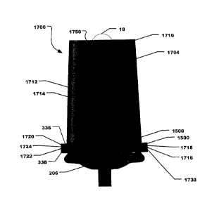
Referring now to FIG. 17, another embodiment of a paint cup assembly is
illustrated
and is designated 1700. As depicted, the paint cup assembly can include a cap
206 and a
paint reservoir 1704 removably engaged therewith. In a particular aspect, the
cap 206 is
identical to the cap 206 shown and described above in conjunction with FIG. 2,
FIG. 3, and
FIG. 13.
The paint reservoir 1704 can include a generally flat, generally round,
substantially
rigid bottom 1710 (the paint cup assembly 1700 is illustrated in an upside
down orientation in
FIG. 17 to depict the manner in which the paint cup assembly 1700 would
typically be used.)
As indicated in FIG. 17, a substantially rigid sidewall 1712 can extend from
the rigid
bottom 1710 to form an internal volume 1714 configured to receive paint. The
sidewall 1712
can include a distal end 1716 formed with a hub 1718. The hub 1718 can be
formed with
threads (not illustrated) that are configured to threadably engage the
external threads 334
formed on the cap 206. In fact, the configuration of the hub 1718 on the paint
reservoir 1704
is substantially identical to the hub 312 formed on the external ring 204. As
such, the paint
reservoir 1704 can be interchangeable with the external ring 204/paint liner
202 on the paint
cap 206 and a user would be able to choose whether to utilize a relatively
rigid paint reservoir
1704 or a collapsible paint liner 202/external ring 204 assembly depending on
the user's
particular preferences and or the particular paint spraying operation to be
performed by the
user.
In a manner similar to the hub 312 formed on the external ring 204, but more
clearly
shown than in FIG. 13, the hub 1718 of the paint reservoir 1704 can include a
primary seal
engagement surface 1720 at the base of the hub 1718 and a secondary seal
engagement
surface 1722 formed on the inner wall of the hub 1718 adjacent to the primary
seal
engagement surface 1720. As illustrated, the secondary seal engagement surface
1722 is
substantially perpendicular to the primary seal engagement surface 1720. When
the paint
reservoir 1704 is engaged with the cap 206, as depicted in FIG. 17, the
primary sealing
structure 336 can engage the primary seal engagement surface 1720 to establish
a primary
seal and the secondary sealing structure 338 can engage the secondary seal
engagement
surface 1722 to form a secondary seal.
Further, a paint containment pocket 1724 can be established, or otherwise
formed,
between the primary seal, the secondary seal, the primary seal surface 1720,
and the
18
CA 02862420 2019-06-27
WO 2013/101946 PCT/US2012/071843
secondary seal surface 1722. The paint containment pocket 1724 can capture and
substantially contain any paint that breaches the primary seal formed between
the primary
sealing structure 336 and the primary seal engagement surface 1720. The seal
207, illustrated
in FIG. 3, FIG. 15, and FIG. 16, can be installed between a distal end 1730 of
the hub 1718
(aka, a cap engagement structure) and the external rim 339 of the cap 206. The
seal 207 can
establish a tertiary seal that can further contain any paint that leaks from
the paint
containment pocket 1724. In order to leak from the paint cup assembly, paint
has to breach
three different seals. Accordingly, the likelihood of paint leaking from the
paint cup
assembly is substantially reduced.
FIG. 17 and FIG. 18 further illustrate that the bottom 1710 of the paint
reservoir 1704
can be formed with an air inlet port 1740. In a particular aspect, the air
inlet port 1740 can be
formed in a center of the bottom 1710 of the paint reservoir 1704.
A valve assembly 1750 can be installed, or otherwise disposed, on the bottom
1710 of
the paint reservoir 1704 adjacent to the air inlet port 1740 so that the valve
assembly 1750 is
in fluid communication with the air inlet port 1740. The valve assembly 1750
can include a
pressure actuated valve assembly. Further, the valve assembly 1750 can include
a flexible
bleeder 1752 and a bleeder retainer 1754. The flexible bleeder 1752 can be
made from a
flexible thermoplastic elastomer (TPE) and the bleeder retainer 1754 can be
made from
polypropylene (PP).
In a particular aspect, the elastic modulus of the TPE used to the construct
the flexible
bleeder 1752 can have an elastic modulus, A,, that can be > 0.150 ksi, such as
> 0.20 ksi,?
0.250 ksi, > 0.30 ksi, or? 0.350 ksi. Further, A, can be < 1.0 ksi, such as <
0.80 ksi, < 0.75
ksi, or < 0.725 ksi. In a particular aspect, A, can be within a range between
and including any
of the maximum and minimum values of X described herein.
For example, X can be > 0.150 ksi and < 1.0 ksi, such as > 0.150 ksi and <
0.80 ksi,?
0.150 ksi and < 0.75 ksi, or? 0.150 ksi and < 0.725 ksi. Further, A, can be?
0.20 ksi and <
1.0 ksi, such as > 0.20 ksi and < 0.80 ksi, > 0.20 ksi and < 0.75 ksi, or >
0.20 ksi and < 0.725
ksi. In another aspect, A, can be > 0.250 ksi and < 1.0 ksi, such as > 0.250
ksi and < 0.80 ksi,
> 0.250 ksi and < 0.75 ksi, or? 0.250 ksi and < 0.725 ksi. Moreover, X, can be
> 0.30 ksi and
<1.0 ksi, such as > 0.30 ksi and < 0.80 ksi, > 0.30 ksi and < 0.75 ksi. or?
0.30 ksi and <
0.725 ksi. Still further, X, can be > 0.350 ksi and < 1.0 ksi, such as > 0.350
ksi and < 0.80 ksi,
> 0.350 ksi and < 0.75 ksi, or? 0.350 ksi and < 0.725 ksi.
19
CA 02862420 2019-06-27
WO 2013/101946
PCT/US2012/071843
The flexible bleeder 1752 can be generally frustoconical and can include a
flat base
1756. An angled wall 1758 can extend from the base 1756 and can include a
distal end 1760.
The distal end 1760 of the angled wall 1758 can be formed with a rim 1762. As
illustrated in
FIG. 17 and FIG. 18. the flat base 1756 of the flexible bleeder 1752 can abut
and block the air
inlet port 1740 formed in the paint reservoir 1704 when the bleeder 1752 is in
the closed
configuration illustrated in FIG. 17 and FIG. 18.
In a particular aspect, the angled wall 1758 of the bleeder 1752 can deform as
the air
pressure is reduced within the paint reservoir 1704. As the angled wall 1758
deforms the
base 1756 of the flexible bleeder 1752 can moved away from the air inlet port
1740.
Accordingly, the flexible bleeder 1752 can move between a closed configuration
in
which the bleeder 1752 blocks the air inlet port 1740 and an open
configuration in which the
bleeder 1752 unblocks the air inlet port 1740. The bleeder 1752 is pressure
actuated and can
move to the open configuration as the air pressure inside the paint reservoir
1704 is reduced.
For example, the air pressure can be reduced within the paint reservoir 1704
as paint is
withdrawn from the paint reservoir 1704 during use of a spray gun attached
thereto.
As indicated in FIG. 17, the bleeder retainer 1754 can be engaged with an
interior
surface of the bottom 1710 of the paint cup reservoir 1704. The bleeder
retainer 1754 can
surround the flexible bleeder 1752. The bleeder retainer 1754 can include a
central hub 1770
that can include an interior 1772 in which the bleeder 1752 is installed or
otherwise disposed.
The central hub 1770 can also include at least one opening 1774 formed therein
to let air pass
through the central hub 1770 when the valve assembly 1750 is opened.
The bleeder retainer 1754 can also include a generally annular rim 1776 that
can
extend outwardly from the central hub 1770. The rim 1776 of the bleeder
retainer 1754 can
surround the air inlet port 1740 and abut the interior surface of the bottom
1710 of the paint
reservoir 1704. The rim 1776 of the bleeder retainer 1754 can be formed with
at least one
engagement bore 1778 through the rim 1776. The paint reservoir 1704 can
include at least
one engagement post 1780 that can extend perpendicularly from the interior
surface of the
bottom 1710 of the paint reservoir 1704. The engagement bore 1778 of the rim
1776 can fit
over the engagement post 1780 and maintain the bleeder retainer 1754 in
engagement with
the bottom 1710 of the paint reservoir 1704. In particular, the engagement
bore engages the
engagement post in an interference fit.
In a particular embodiment, the valve assembly 1750 can be operable to move
between a closed configuration, in which air flow through the air inlet port
1740 is prevented,
CA 02862420 2019-06-27
WO 2013/101946 PCT/US2012/071843
and an open configuration, in which air flow through the air inlet port 1740
is permitted, upon
actuation of a spray gun coupled to the paint cup assembly 1700. The valve
assembly 1750
can be pressure actuated and a change in pressure within the paint cup
assembly 1700 can
cause the valve assembly 1750 to move to the open configuration. The open
configuration
can be achieved automatically upon actuation of the spray gun.
In a particular aspect, the valve assembly 1750 can move to the open
configuration at
least partially based on the operating air pressure, PO, of the spray gun,
i.e., the pressure of
pressurized air flowing through the spray gun. In a particular aspect, PO can
be? 10 psi,
such as? 15 psi, > 20 psi, > 25 psi, or? 30 psi. Further, PO can be < 50 psi,
such as < 45 psi,
or < 35 psi. Further, PO can be within a range between and including any of
the minimum
and maximum pressure values describe above.
For example, PO can be > 10 psi and < 50 psi, such as > 10 psi and < 45 psi,
or > 10
psi and < 35 psi. PO can be > 15 psi and < 50 psi, such as > 15 psi and < 45
psi. or > 15 psi
and < 35 psi. PO can be > 20 psi and < 50 psi, such as > 20 psi and < 45 psi,
or? 20 psi and
<35 psi. Further, PO can be > 25 psi and < 50 psi, such as > 25 psi and < 45
psi, or > 25 psi
and < 35 psi. Further still, PO can be > 30 psi and < 50 psi, such as > 30 psi
and < 45 psi. or
> 30 psi and < 35 psi.
In a particular aspect, the actuation pressure, PA, to open the valve assembly
1750 can
be < PO. For example, the PA can be < 5 psi, such as < 4 psi, or < 3 psi.
Further, PA can be
> 1 psi, such as? 1.5 psi, or > 2 psi. Further, PA can be within a range
between and
including any of the minimum and maximum pressure values describe above.
For example, PA can be < 5 psi and? 1 psi, such as < 5 psi and? 1.5 psi, or <
5 psi
and > 2 psi. PA can be < 4 psi and > 1 psi, such as < 4 psi and > 1.5 psi, or
< 4 psi and > 2
psi. Moreover, PA can be < 3 psi and? 1 psi, such as < 3 psi and? 1.5 psi, or
< 3 psi and? 2
psi.
It another aspect, the valve assembly 1750 can substantially prevent paint
from
leaking out of the air inlet port 1740 when the valve assembly 1750 is in the
closed
configuration and the paint cup assembly 1700 is standing substantially
upright on the bottom
1710 of the paint reservoir 1704 (rotated 180 from the orientation
illustrated in FIG. 17).
With the configuration described herein, the convertible paint cup assembly
provides
a paint cup assembly having a single cap onto which at least two different
paint reservoirs can
be threaded. The paint cup assembly can include a paint reservoir that
includes a collapsible
liner or a rigid paint reservoir. Moreover, the collapsible liner can be used
with the extended
21
CA 02862420 2019-06-27
WO 2013/101946 PCT/US2012/071843
ring or installed inside the rigid paint reservoir. Also, the extended ring
can be configured to
fit into the rigid paint reservoir so that the rigid paint reservoir can be
used to support the
extended ring and collapsible paint liner while being filled.
A user can select which type of paint reservoir to use based on the paint
process or the
user preferences. Further, the rigid paint reservoir includes an air inlet and
a valve assembly.
The valve assembly can automatically allow the infiltration of air into the
rigid paint reservoir
upon actuation of the paint sprayer.
Note that not all of the activities described above in the general description
or the
examples are required, that a portion of a specific activity may not be
required, and that one
or more further activities may be performed in addition to those described.
Still further, the
order in which activities are listed is not necessarily the order in which
they are performed.
Certain features that are, for clarity, described herein in the context of
separate
embodiments, may also be provided in combination in a single embodiment.
Conversely,
various features that are, for brevity, described in the context of a single
embodiment, may
also be provided separately or in any subcombination. Further, reference to
values stated in
ranges includes each and every value within that range.
Benefits, other advantages, and solutions to problems have been described
above with
regard to specific embodiments. However, the benefits, advantages, solutions
to problems,
and any feature(s) that may cause any benefit, advantage, or solution to occur
or become
more pronounced are not to be construed as a critical, required, or essential
feature of any or
all the claims.
The specification and illustrations of the embodiments described herein are
intended
to provide a general understanding of the structure of the various
embodiments. The
specification and illustrations are not intended to serve as an exhaustive and
comprehensive
description of all of the elements and features of apparatus and systems that
use the structures
or methods described herein. Separate embodiments may also be provided in
combination in
a single embodiment, and conversely, various features that are, for brevity,
described in the
context of a single embodiment, may also be provided separately or in any
subcombination.
Further, reference to values stated in ranges includes each and every value
within that range.
Many other embodiments may be apparent to skilled artisans only after reading
this
specification. Other embodiments may be used and derived from the disclosure,
such that a
structural substitution, logical substitution, or another change may be made
without departing
22
CA 02862420 2019-06-27
WO 2013/101946
PCT/US2012/071843
from the scope of the disclosure. Accordingly, the disclosure is to be
regarded as illustrative
rather than restrictive.
23