Note: Descriptions are shown in the official language in which they were submitted.
DRAIN MASTS
BACKGROUND OF THE INVENTION
1. Field of the Invention
The present disclosure relates to drains, and more particularly to drain masts
such as
used to drain liquids from within an aircraft to the exterior of the aircraft.
2. Description of Related Art
An aircraft drain mast whether for water, fuel, or other liquids, protrudes
from the
fuselage into the airstream far enough that the discharged media is cleanly
swept away such
that it does not reattach to the aircraft. For example, a drain mast can be
used to drain
condensation and/or fuel leakage from the inner to outer tube gap in a double
walled fuel line.
The geometry and size of the drain mast, e.g., height, width, length and
airfoil shape,
contribute to drag components, which are items to be minimized for maximizing
fuel
consumption and range. Many conventional drain masts are built with full
length tubes and
can require significant efforts to repair a damaged tube, such as dismantling
the mast with
subsequent reassembly, repainting and retesting.
Such conventional methods and systems have generally been considered
satisfactory
for their intended purpose. However, there is still a need in the art for
improved drain masts
and methods of making drain masts. The present disclosure provides a solution
for these
problems.
1
Date Recue/Date Received 2020-06-08
CA 02862539 2014-09-10
SUMMARY OF THE INVENTION
A drain mast includes a first fairing body defining a first fairing wall and a
first drain
portion. A second fairing body defines a second fairing wall and a second
drain portion. The
first and second fairing bodies are joined together as a fairing with the
first and second fairing
walls as opposed exterior fairing walls, and with the first and second drain
portions joined to
form a drain passage through the fairing from a drain passage inlet to a drain
passage outlet.
In accordance with certain embodiments, the first drain portion includes a
first drain
channel, the second drain portion includes a second drain channel, and the
first and second
drain channels are joined defining the drain passage therebetween. The opposed
exterior
fairing walls can define an airfoil from a leading edge of the fairing to a
trailing edge of the
fairing, and the opposed exterior fairing walls can be joined to one another
at a seam along
the leading and trailing edges of the fairing. An inlet nipple can be
connected in fluid
communication with the drain passage inlet. The first fairing body can include
a first
mounting flange portion, the second fairing body can include a second mounting
flange
portion, and the first and second mounting flange portions can be joined
together as a
mounting flange surrounding the drain passage inlet for mounting the fairing
to an aircraft.
It is contemplated that the first and second fairing bodies can be
substantially
symmetrical across a plane defined by a seam where the first and second
fairing bodies are
joined together. The first and second fairing bodies can be non-metallic, e.g.
fiberglass, and
can be joined together by an adhesive, e.g., epoxy. A portion of the first
fairing body can
include a groove, and a portion of the second fairing body can include a
tongue engaged with
the groove of the first fairing body.
In certain embodiments, the fairing defines opposed leading and tailing edges,
wherein a first void is defined within the fairing between the drain passage
and the leading
2
CA 02862539 2014-09-10
edge, and wherein a second void is defined within the fairing between the
drain passage and
the trailing edge. The first void can be in fluid communication with a space
exterior to the
fairing through a vent defined in the fairing. Similarly, the second void can
be in fluid
communication with a space exterior to the fairing through a vent defined in
the fairing.
A method of making a drain mast includes joining a first fairing body as
described
above to a second fairing body as described above to form a fairing. The
method can further
include joining an inlet nipple to the fairing in fluid communication with the
drain passage
inlet. Joining the first fairing body to the second fairing body can include
applying an
adhesive to at least one of the first and second drain portions, and adhering
the first and
second fairing bodies together with the adhesive.
These and other features of the systems and methods of the subject disclosure
will
become more readily apparent to those skilled in the art from the following
detailed
description of the preferred embodiments taken in conjunction with the
drawings.
3
CA 02862539 2014-09-10
BRIEF DESCRIPTION OF THE DRAWINGS
So that those skilled in the art to which the subject disclosure appertains
will readily
understand how to make and use the devices and methods of the subject
disclosure without
undue experimentation, preferred embodiments thereof will be described in
detail herein
below with reference to certain figures, wherein:
Fig. 1 is a perspective view of an exemplary embodiment of a drain mast
constructed
in accordance with the present disclosure, showing the drain passage outlet of
the drain mast
fairing;
Fig. 2 is a perspective view of the drain mast of Fig. 1, showing the inlet
nipple joined
to the drain passage inlet;
Fig. 3 is a side elevation view of a first fairing body of the fairing of Fig.
1, showing
the interior of the fairing including the first portion of the drain passage,
with the second
fairing body removed;
Fig. 4 is a cross-sectional side elevation view of another exemplary
embodiment of an
inlet nipple for use with the drain mast of Fig. 1, showing an angled conduit;
Fig. 5 is a cross-sectional side elevation view of another exemplary
embodiment of an
inlet nipple for use with the drain mast of Fig. 1, showing a conduit with
seal members at the
inlet end thereof;
Fig. 6 is a cross-sectional end elevation view of a portion of the drain mast
of Fig. 1
taken at the corresponding cross-section indicated in Fig. 3, showing the
tongue and grove
engagement of the first and second fairing bodies;
Fig. 7 is an exploded cross-sectional end elevation view of a portion of the
drain mast
of Fig. 1 taken at the corresponding cross-section indicated in Fig. 3,
showing the tongue and
grove engagement of the first and second fairing bodies; and
4
CA 02862539 2014-09-10
Fig. 8 is an end view of the inlet nipple of Fig. 3, showing the end flange
with anti-
rotation flats.
CA 02862539 2014-09-10
DETAILED DESCRIPTION OF THE PREFERRED EMBODIMENTS
Reference will now be made to the drawings wherein like reference numerals
identify
similar structural features or aspects of the subject disclosure. For purposes
of explanation
and illustration, and not limitation, a partial view of an exemplary
embodiment of drain mast
in accordance with the disclosure is shown in Fig. 1 and is designated
generally by reference
character 100. Other embodiments of drain masts in accordance with the
disclosure, or
aspects thereof, are provided in Figs. 2-7, as will be described. The systems
and methods
described herein can be used to provide improved drain masts, for example in
aerospace
applications.
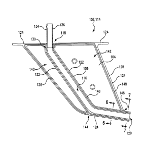
Drain mast 100 includes a first fairing body 102 defining a first fairing wall
104 and a
first drain portion 106 (first fairing wall 104 and first drain portion 106
are identified in Fig.
3). A second fairing body 108 defines a second fairing wall 110 and a second
drain portion
112. Referring to Fig. 2, the first and second fairing bodies 102 and 108 are
joined together
as a fairing 114 with the first and second fairing walls 104 and 110 forming
opposed exterior
fairing walls, and with the first and second drain portions 106 and 112 joined
to form a drain
passage 116 (indicated in Fig. 3) through the fairing from a drain passage
inlet 118 to a drain
passage outlet 120.
First and second fairing bodies 102 and 108 are substantially symmetrical
across a
plane defined by a seam 124 where the first and second fairing bodies are
joined together.
Various portions of seam 124 are indicated in each of Figs. 1-3. The opposed
exterior fairing
walls, i.e., first and second fairing walls 104 and 110, define an airfoil
from a leading edge
126 of fairing 114 to a trailing edge 128 of fairing 114. Seam 124 includes
portions where
the opposed exterior fairing walls are joined to one another along the leading
and trailing
edges 126 and 128 of fairing 114. First fairing body 102 includes a first
mounting flange
portion 130, and second fairing body 108 includes a second mounting flange
portion 132.
6
CA 02862539 2014-09-10
First and second mounting flange portions 130 and 132 are joined together as a
mounting
flange surrounding the drain passage inlet 118, and can be used for mounting
the fairing to an
aircraft, for example using fasteners in the holes shown in the mounting
flange portions 130
and 132 in Figs. 1 and 2.
With reference now to Fig. 3, first fairing body 102 is shown without second
fairing
body 108 to show the internal structure. First drain portion 106 includes a
first drain channel
defined by the sidewalls 122 of first drain portion 106, and the bottom of the
channel which
includes the portion of first fairing wall 104 between the sidewalls 122.
Second drain portion
112 includes a second drain channel with the same general channel structure,
but in mirrored
symmetry, as shown in Fig. 3 for first drain portion 106. When joined together
as shown in
Figs. 1 and 2, the first and second drain channels are joined to define the
complete drain
passage 116 therebetween. Unlike conventional designs where the drain is
provided as a
separate pipe assembled into a fairing, the drain passage 116 is formed
integral with the
fairing walls when the first and second fairing portions 102 and 108 are
joined together.
An inlet nipple 134 is connected in fluid communication with drain passage
inlet 118.
Inlet nipple 134 includes a straight conduit 136. The mounting gland for inlet
nipple 134 is
part of the first and second fairing portions 102 and 108. Inlet nipple 134 is
bonded to the
first and second fairing portions 102 and 108, and these three components
become one solid
piece. As shown in Fig. 8, inlet nipple 134 includes an end flange with flats
138. The
mounting gland of inlet 118 includes a double d structure, wherein the flat
sides, i.e., anti-
rotation dogs 139, thereof are substantially equal to the tube diameter of
inlet nipple 134.
Flats 138 and dogs 139 cooperate to resist any rotation loads on inlet nipple
134 to minimize
the chance of breaking the bond. Fig. 4 shows another exemplary embodiment of
an inlet
nipple 234 that can be used in lieu of inlet nipple 134. Inlet nipple 234 is
similar to inlet
nipple 134 except that conduit 236 is bent. Fig. 5 shows yet another exemplary
inlet nipple
7
CA 02862539 2014-09-10
334 similar to inlet nipple 134 except that conduit 336 has a different type
of interface 337
wherein the seal members are at the inlet end of conduit 336. The different
inlet nipples 134,
234, and 334 of Figs. 3-5 are shown to demonstrate the interchangeability of
inlet nipples
used with drain mast 100. This can allow drain mast 100 to be adapted to
connect with any
suitable drain interface, and those skilled in the art will readily appreciate
that any other
suitable type of inlet nipple can be used without departing from the scope of
this disclosure.
Inlet nipples 134, 234, and 334 can be made of G-10 fiberglass loaded epoxy,
for example, or
of any other suitable material.
With continued reference to Fig. 3, a first void 140 is defined within fairing
114
between drain passage 116 and leading edge 126, with portions of first and
second fairing
walls 104 and 110 and the mounting flange also bounding void 140. A second
void 142 is
defined within fairing 114 between drain passage 116 and trailing edge 128,
with portions of
first and second fairing walls 104 and 110 and the mounting flange also
bounding void 142.
First void 140 is in fluid communication with the space exterior to fairing
114 through a vent
144 defined in fairing 114. Similarly, second void 142 is in fluid
communication with the
space exterior to fairing 114 through a vent 146 defined in the fairing. Vents
144 and 146
allow voids 140 and 142 to equalize pressure as fairing 114 is exposed to
varying external
pressures, as in a climbing and descending aircraft.
With reference now to Fig. 6, the cross section 6-6 of drain mast 100
indicated in Fig.
3 is shown. A portion of the first fairing body 102 includes a groove 148, and
a portion of
second fairing body 108 includes a tongue 150 engaged with groove 148. Tongue
and groove
148 and 150 substantially surround void 142, as indicated in Fig. 3. A similar
tongue and
groove substantially surrounds void 140. The tongue and groove elements of
first and second
fairing bodies 102 and 108 are an exception to their substantial mirrored
symmetry, and this
configuration provides resistance to relative sliding of first and second
fairing bodies 102 and
8
CA 02862539 2014-09-10
108 during assembly, as well as resistance to shearing along seam 124 when
drain mast 100
is completely assembled.
Referring now to Fig. 7, the cross-section 7-7 of drain mast 100 indicated in
Fig. 3 is
shown, with first and second fairing bodies 102 and 108 shown separated. Also
schematically shown is adhesive 152 used to join first and second fairing
bodies 102 and 108.
It is contemplated that first and second fairing bodies 102 and 108 can be
entirely non-
metallic, e.g. compression molded using a sheet molding compound (SMC),
Michigan, and
that adhesive 152 can be a structural grade epoxy, for example. Those skilled
in the art will
readily appreciate that these materials are exemplary only, and that any other
suitable
materials and joining techniques can be used without departing from the scope
of this
disclosure. For example, it is possible that a metallic fairing could be
constructed in
accordance with this disclosure wherein the joining is accomplished by
brazing. However for
the following description of a method of assembly, the exemplary context of
fiberglass and
epoxy is used.
An exemplary method of making a drain mast, e.g., drain mast 100, includes
joining a
first fairing body, e.g. first fairing body 102 as described above, to a
second fairing body, e.g.,
second fairing body 108 as described above, to form a fairing, e.g., fairing
114 described
above. An inlet nipple, e.g., inlet nipples 134, 234, and 334 described above,
can be joined to
the fairing in fluid communication with the drain passage inlet, e.g. drain
passage inlet 118.
Joining the first fairing body to the second fairing body can include applying
an adhesive, e.g..
adhesive 152 which can be an epoxy, to at least one of the first and second
drain portions, and
adhering the first and second fairing bodies together with the adhesive.
Joining the fairing
bodies in this manner forms a pressure tight, fluid tolerant drainage tube
flow path, e.g., drain
passage 116 is pressure tight relative to voids 140 and 142, and is pressure
tight along its
length from drain passage inlet 118 to drain passage outlet 120.
9
CA 02862539 2014-09-10
In particular, the epoxy can be applied to the tongue and groove portions of
the first
and second fairing bodies. Epoxy can also be applied to any other seam
portions of the first
and second fairing bodies. If vents, e.g., vents 144 and 146, are included,
care should be used
to prevent blockage of the vents when applying the epoxy. With the epoxy
applied, the first
and second fairing bodies can be clamped together for curing of the epoxy. The
inlet nipple
can be joined to the fairing using the same epoxy after the first and second
fairing bodies are
joined, or the inlet nipple can be mounted with epoxy to one of the fairing
bodies prior to
assembling the fairing bodies together. The inlet nipple could also be sealed
to an airframe
first, and then the drain mast could be pushed onto inlet nipple. In the
foregoing manner, a
drain mast is formed with the drain tube as an integral part of the airfoil.
The inlet nipple can
be removed and replaced without disassembling the fairing.
A potential advantage of building the fairing airfoil with an integral drain
tube is that
the width component of the airfoil, e.g., the width of the drain mast as
viewed in Fig. 6, and
the resultant drag can be reduced compared to conventional designs, since the
fairing wall is
used as part of the drain tube wall. In another aspect of this potential
advantage, with an
integral drain tube as disclosed herein, no tube to fairing wall clearance is
needed. An
integral drain tube also provides the potential advantages of lower part count
and cost of
manufacture.
While shown and described in the exemplary context of drains for aircraft,
those
skilled in the art will readily appreciate that drain masts in accordance with
this disclosure
can be used in any other suitable application.
The methods and systems of the present disclosure, as described above and
shown in
the drawings, provide for drain masts with superior properties including ease
of manufacture
and repair as well as the potential for reduced drag. While the apparatus and
methods of the
subject disclosure have been shown and described with reference to preferred
embodiments,
CA 02862539 2014-09-10
those skilled in the art will readily appreciate that changes and/or
modifications may be made
thereto without departing from the spirit and scope of the subject disclosure.
11