Note: Descriptions are shown in the official language in which they were submitted.
CA 02862639 2014-06-30
WO 2013/101957 PCT/US2012/071865
-1-
PRODUCT CUSTOMIZATION SYSTEM AND METHOD
Charles Ohiaeri, San Francisco, CA
Young Harvill, Half Moon Bay, CA
Robert I. Beaver III, San Francisco, CA
Priority Claims/Related Applications
This application claims priority to under 35 USC 120 and is a continuation in
part of
U.S. Patent Application Serial No. 12/546,582, filed on August 24, 2009 and
entitled
"Product Customization System and Method," which application in turn claims
priority under
35 USC 119(e) and 120 to U.S. Provisional Patent Application Serial No.
61/091,316, filed
on August 22, 2008 and entitled "Product Customization System and Method", all
of which
are incorporated herein by reference.
Field
The system relates to a product customizing system and method.
Background
Markings for the purpose of information, ornamentation, expression, and
fashion are
applied to products with a variety of means. Until recently relatively few
designs of product
have been produced in large volumes. Just In Time (JIT) Manufacturing
processes have
enabled the production of many designs in production runs from 1 to 100 using
custom
marking of product surfaces with techniques such as inkjet printing and other
digital print
methods. There are also a class of technologies which may produce volumetric
forms (3d
objects) through the use of Stereo Lithography, Fused Deposition Modeling, and
other
processes. Currently there is not a unified method for the commercial design
and
manufacturing of layered optically-active surfaces for products with a complex
curved form.
There are systems for managing and applying a specialized subset of films
(Cyan, Magenta
and Yellow process color films) and for manufacturing custom lenses and
gratings for the
optics industry, but not for the interactive application of component based
optical surfaces on
commercial products. Thus, it is desirable to provide a customized product
system and
method that allows a consumer to provide user content that is then applied to
the product and
it is to this end that the system and method are directed.
CA 02862639 2014-06-30
WO 2013/101957 PCT/US2012/071865
-2-
Brief Description of the Drawings
Figure 1A illustrates an example of an embodiment of a product customization
system;
Figure 1B illustrates more details of the product customization unit that is
part of the
product customization system;
Figure 1C illustrates an implementation of a method for product customization;
Figures 2A and 2B illustrate an example of a product view user interface of
the
product customization system;
Figure 3 illustrates an example of a product design user interface of the
product
customization system;
Figures 4A and 4B illustrate an example of a product view user interface of
the
product customization system when a product has a customized user design;
Figure 5 illustrates more details of the manufacturing process;
Figure 6 illustrates an example of a carrier with a design; and
Figure 7 illustrates a manufactured skateboard with the user design.
Detailed Description of One or More Embodiments
The system and method are particularly applicable to web-based client/server
architecture system for a skateboard customization system and method
implemented in
software on a computer as described below and it is in this context that the
system and
method will be described. It will be appreciated, however, that the system and
method can be
used to customize any product in which it would be desirable to allow a
consumer/user to
insert user content onto a product with an uneven surface/texture that can be
manufactured by
the system. For example, the system may be used to design customized
skateboards (the
example described below), customized globes, customized baseball bats,
customized car tops,
or any other product with an uneven/textured surface in which a user might
want to add a
customized design. In addition, the system and method can be implemented in
software
(shown in the illustrated implementation), hardware or a combination of
hardware and
CA 02862639 2014-06-30
WO 2013/101957 PCT/US2012/071865
-3-
software and may also be implemented on client/server system (shown in the
illustrated
implementation), a web server, a terminal, a peer to peer system and the like
so that the
system and method are not limited to the particular implementation of the
system or method.
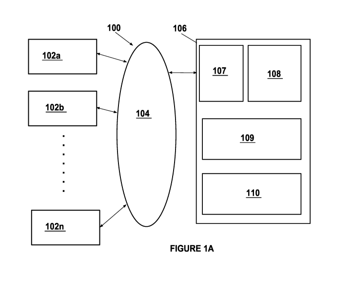
Figure 1A illustrates an example of an implementation of a product
customization
system 100. The system may include one or more consumer computing devices 102,
such as
102a, 102b, ..., 102n, wherein each computing device has at least one
processing unit,
memory, some persistent memory, some other memory, a display device and
input/output
devices and each may be a personal computer, mobile device, cellular device,
wireless email
device, converged device such as a Treo or Blackberry and the like that permit
the consumer
to interact with the consumer computing device as well as the system through
an application,
such as for example a known browser application, being executed by the
consumer computing
device. Each consumer computing device may establish a connection with and
communicate
over a link 104 using a typical secure or unsecure protocol with a product
customization unit
106. The link 104 may be implemented using a computer network, a cellular
network, a
wired or wireless link and the like, In one embodiment, the link is the
Internet. The product
customization unit 106 may be implemented in hardware, software or a
combination of
hardware and software. In one embodiment, the product customization unit 106
may be one
or more server computers that execute a plurality of lines of computer code to
perform the
functions and operations of the product customization unit 106 as described
below.
In one illustrative embodiment, the product customization unit 106 may further
comprise at least one web server 107 (implemented in hardware or software or a
combination
of the two) that establishes a connection with each consumer computer device,
receives
requests from each consumer computer device and communicates data and
information (such
as by using one or more web pages) and requests for consumer computer device
information
to each consumer computer device wherein the consumer computer device
interacts with the
web server using a known secure or unsecure protocol and a typical browser
application. The
at least one web server, for example, may serve a web page that allows the
consumer to
browse the available products and designs and then, using the product
customization system,
customize the particular design of a particular product using user content.
The product
customization unit may further include a store 108 that contains and stores
the relevant
information for the product customization unit including the product
information and images
for the web pages, customization data, etc. The product customization unit may
further
CA 02862639 2014-06-30
WO 2013/101957 PCT/US2012/071865
-4-
comprise a product customizer 109 (that may be implemented as a plurality of
lines of
computer code wherein the plurality of lines of computer code are executed by
the processing
unit(s) of the server computers to implement the product customization system)
that allows a
consumer to customize a product, allows a consumer to upload user content
(images and/or
text), allows the consumer to place the user content on the product, allows
the consumer to
view the customized product for all angles, allows the consumer to customize
various features
of the product, and manufacture the customized product once it has been
designed as
described below in more detail. The product customization unit may further
comprise a well
known ecommerce engine 110 that, once the consumer has customized a product
with
particular user content, may allow the consumer to purchase the customized
product. In one
implementation, the product customization system may also be part of a larger
web
site/system such as, for example, www.zazzle,com.
The system and method described above may be used by a user or designer to
select
and place surfaces with a variety of optical qualities and effects on a
product which has a
complex curved form. The system and method include methods for the manufacture
of these
products, for creating a model of the surface qualities, for displaying images
of the products
interactively to the user and for calibrating those images based on output of
finished product.
The system allows a consumer to control apparent color and color changes over
viewing angles (as shown in the user interface examples described below), the
surface
reflectivity (gloss) of the surface, and the apparent depth of visual elements
within the
product surface. The system also incorporates a manufacturing process which
can apply a
material in a specific location on a substrate wherein the material may be
bonded to the
substrate through the interaction of the material with light, heat,
evaporation, electrical
charge, or triggered catalytic process. For example when light is used for the
bonding
process, the time at which the light is applied, the intensity and the
location of light affects the
shape of the material deposit as it bonds to the substrate and to its
neighboring material
deposits and forms a film that whose characteristics change in response to the
character of the
light. Then, additional materials may be deposited to form layers of deposited
films on the
substrate with a variety of surface depths and textures. These surface
characteristics can
produce these properties:
1. diffuse (matte) surface.
2. smooth (gloss) surface.
CA 02862639 2014-06-30
WO 2013/101957
PCT/US2012/071865
-5-
3. figured (Fresnel) surface.
4. Refractive (grating) surface.
5. patterned surface.
For example, the substrate may be layered with opaque cut film that may be
used to
replace opaque printing as described above or the substrate may be layered
with subtractive
cuts to product relief surfaces for overprint such as laser etching or "sunken-
relief'. The
substrate may also be layered with printing passes to produce relief surfaces
for overprint
("bas-relief'). The substrate may also be layered to produce alto/high reliefs
(See
http://ermikipedia.orgiwikitRelief which is incorporated herein by reference
for a definition
of the different types of reliefs).
Further, the set of materials deposited on the substrate may have a wide
variety of
different optical properties:
1. Transparency or Opacity
2. Refractive Index
3. Absorption Spectra
4. Reflectivity
5. Light Phase Change (quarter and half wave effects)
6. Polarization changes.
The interaction of these materials in layers may change a wavefront of light
which
strikes it due to a variety of optical effects within the layered film:
1. Surface Reflection
2. Internal Occlusion by layer (opaque regions separated by transparency)
3. Refraction by Refractive Index change.
4. Reflection by constructive interference (Lippmann-Bragg effect)
5. Refraction by interference (Grating effect)
6. Attenuation through polarization.
7. Attenuation of reflection through spectral absorption.
8. Attenuation of transmission through spectral absorption.
CA 02862639 2014-06-30
WO 2013/101957 PCT/US2012/071865
-6-
9. Diffusion (translucent regions over dark regions).
The substrate to which these materials are applied may be either a receiver
sheet, or a
bonding sheet.
In the receiver sheet case:
1. The receiver sheet may be optically or mechanically figured to produce
the
product surface texture.
2. Optically active layers are applied in the viewer to product surface
direction.
3. A product bonding layer is applied last
4. The film layer is applied to the complex curved surface of the product
using
pressure and heat.
5. Trimming is performed.
6. The receiver is removed.
In the bonding sheet case:
1. Optically active layers are applied in the product surface to
view direction.
2. The final layer may be transparent and may figured by timed attenuation
of
light.
3. The film layer is applied to the complex curved surface of the product
using
pressure and heat.
4. Trimming is performed.
At startup, a set of reference film layers are made to characterize the
transport of light
through layers produced by a specific manufacturing system. These reference
films are used
to characterize and model the light transport within chosen layer groups.
These groups
optimize each optical effect, such as occlusion, The method for modeling this
interaction is
described later as the Layered Light Transport Component. A transport function
is built for
each reference film unit. Surface texture libraries are built by layering
models of reference-
film units interactively, these may be specified at the pixel level. Finished
textures are
compiled into a simplified Layered Light Transport Material, and may be
selected and applied
by Users and Designers. The resulting design can be viewed interactively.
CA 02862639 2014-06-30
WO 2013/101957 PCT/US2012/071865
-7-
For purposes of illustrating the product customization system and method, a
product
customization method and user interface for a skateboard upon which user
content is placed is
described below. However, the product customization system may also be used
for other
products with uneven/textured surfaces in which it is desirable to provide a
consumer with the
ability to customize the product with user content.
Figure 1B illustrates more details of the product customization unit 109 that
is part of
the product customization system. In particular, the product customization
unit may further
comprise a user interface portion 109a, a user product renderer portion 109b,
a layered light
transport model 109c, a manufacturing product renderer portion 109d, a
manufacturing
portion 109e and a reflection portion 109f. In one implementation, each of
these portions
may be implemented using a combination of hardware and software. Each of these
portions
of the product customization unit 109 are described in further detail with
reference to Figure
1C.
Figure 1C illustrates an implementation of a method 120 for product
customization
that may be implemented, for example, by the product customization system
shown in Figure
1A. The method allows the manufacture of user designed products and the method
applies
user created colors and designs to a product made out of layers of material
with specific
optical qualities in one embodiment.
User Interface Portion
The product customization system permits a user/consumer to customize a
product
using the user interface portion 109a (122) that may be implemented as one
more web pages
in one embodiment. The user interface portion 109a allows the user to
interactively apply a
design to a product, such as a skateboard as described below in more detail.
The data
generated by the user interface portion may include user account data, a
product description
(that describes the user's custom product), user image designs (that contains
the user content),
color choice (the color(s) chosen by the user), material choice (the type of
material for the
custom product) and the finishing choice (the finishing selected by the user
for the custom
product). The user interface portion allows the user or designer to perform
the following
processes using the user interface:
1. Select a Skateboard style and size. (See Figure 2A and 2B which are
described
below)
2. Select or upload a design containing these items:
CA 02862639 2014-06-30
WO 2013/101957
PCT/US2012/071865
-8-
a. Text.
b. Images
c. Vector Designs
3. Choose a product Design Area
a. Apply design items, and position on 2d surface of design area.
b. The UI will request and show a rendering of the product with the applied
design.
4. Choose a product Design View
a. Apply design items projected from view on 3d surface of product from
View
direction.
b. The UI will request and show a rendering of the product with the applied
design.
5. Choose a surface quality (material)
a. Choose a design item, apply a surface quality from a list.
b. The UI will request and show a rendering of the product with the new
surface
quality.
6. Change and Update the Design (repeat processes 2 through 5
above).
7. Choose to purchase design on product.
a. UI processes payment choice.
The user interface portion may also assemble a set of instruction that
describe the user
design and requests images of the final product from the user product renderer
portion 109b.
The product customization system then renders the customized product for the
user/consumer
(124) using the user product renderer portion 109b. The user product renderer
portion takes
the data/information/description (based on the user interactions with the user
interface
portion) and other user preferences and using information supplied by the
reflection portion
109f, synthesizes an image of the manufactured product that is then displayed
to the
user/consumer.
User Renderer Portion
In more detail, the user product renderer portion may perform the following
processes:
CA 02862639 2014-06-30
WO 2013/101957
PCT/US2012/071865
-9-
1. Accepts a UI request for a rendering of a custom product.
a. The Request contains:
i. Product Style
ii. Product Size
iii. User designs
1. Images
2. Vector Graphics
3. Text
iv. User design properties
1. Placement Coordinates in Design Area space.
a. Position
b. Rotation
c. Scale
2. Surface Qualities
a. Surface selection for each Design Area
b. Color
c. Shininess
v. The User Viewing Geometry
vi. The User Lighting Geometry
2. Assembles a request for the Layered Light Transport Model for a compiled
light transport model for this product, with the supplied view and lighting.
3. Renders the compiled light transport model onto the Product geometry.
4. Returns the rendered product to the User Interface component.
The reflection portion 109f (which provides feedback throughout the product
customization unit) generates calibrated color maps and calibrated luminance
maps to the
calibrated product render assets (including geometry, luminance maps, color
maps and safe
area coverage maps) that are used to generate the images for the product.
CA 02862639 2014-06-30
WO 2013/101957 PCT/US2012/071865
-10-
Light Transport Modeling
The product customization system then performs light transport modeling
process
(125). The Layered Light Transport Model contains a library of optical
interactions between
selected layers of materials. The number of layers and therefore the number of
interactions is
limited by manufacturing constraints. More layers can produce a greater
variety of effects, but
increase the cost of manufacturing the product. For each product a subset of
optical
interactions may be chosen. For the purposes of a premium Skateboard product,
the
following layering is used (described from product bonding layer toward
viewer).
1. Product Surface (wood grain)
2. Product Bonding layer (transparent)
3. Opaque Reflector: Microfine Titanium Dioxide pigment in UV activated
binder.
4. Macrolayer of transmission attenuated spectral absorption material
(pigment)
in UV activated transparent binder.
5. UV activated transparent material (refractive index varies from layers
4).
6. Occluding macrolayer (single opaque reflective absorption, or repeat of
layers
3 and 4) in UV activated transparent binder.
7. UV activated transparent material with figured surface. (refractive
index varies
from layers 5 and 4)
The layered light transport component uses the thin film geometry of the
optical
system to simplify a light transport model. It represents each pixel in a
printed layer as a
referenced volume cell that has 2d angular light inputs and outputs. Each
reference volume
contains a list of functions to process light inputs and outputs, and
calibrated values for each
function based on measured response from reference films. Since each volume
cell has a
known position, the light transport network may be implicitly linked. A
request from the
User Renderer is used to build the volume cell layers. Compiled stacks of
volume cells may
be placed at each design pixel by reference. The Layered Light Transport Model
then uses
the supplied light and view vectors to traverse the transport model and
compile a
textureInput-lightOutput map for the view and lighting of a specific product
with user
configured surfaces.
CA 02862639 2014-06-30
WO 2013/101957
PCT/US2012/071865
-11-
In this case, layered light transport reference films would be manufactured
for these
optical interactions:
1. Layer 7 interaction with layers 3 and 4.
a. Refracted light input into layer 3 based on 2d surface modulation of layer
7.
b. Refracted light output from layer 3 and 4 based on surface modulation of
layer
7.
2. Layer 7, Refractive properties based on grating surface modulation.
3. Layer 6 interaction with layers 3 and 4 with modulation of Layer 5.
a. Occluded light input into layer 3 with modulation of Layer 5.
b. Occluded light output from layer 4 based on modulation of Layers 4 and 5.
4. Layers 7, 5 and 4 interaction.
a. Reflection from Constructive Interference based on attenuation
of Layer 5.
5. Layer 6 and 4 interaction.
a. Diffusion of light with modulation of absorption of 4 and
opacity of 6.
6. Layer 3 and 4 interaction.
a. Response curves for pigment layers 4 and reflectance of layer
3.
These 6 reference films are manufactured with the needed modulation and are
then
measured over angular input and output ranges for the volume cell, and each is
characterized
as a function with associated response values.
Manufacturing Product Renderer Portion
The product customization system then renders the customized product for the
manufacturer (126) using the manufacturing product renderer portion 109d. The
Manufacturing Renderer takes the User product request, and renders the layers
and printing
instructions needed to print layers on the bonding or receiving film. For each
design layer, it
positions the user designs using the supplied coordinate systems, tags each
pixel with color
and surface information, and renders each layer by looking up the layer stack
for each surface
index. The design is reverse-warped based on data from the reflection
interface, so that it will
be aligned properly after heat transfer to the complex curved surface.
Manufacturing Portion
CA 02862639 2014-06-30
WO 2013/101957 PCT/US2012/071865
-12-
The product customization system then manufactures the customized product
(128)
using the manufacturing portion 109d. The manufacturing portion performs, for
example, the
following processes: 1) manufactures the customized design product; 2) ships
the product
based on the Operator directions; and/or 3) gathers product information for
the Reflection
portion (including patterns, reference product with calibration mark-up and/or
color and
material samples) that are input to a modelshot processing component that
performs various
modelshot processing tasks as described in more detail in U.S. Patent
Application Serial No.
11/925,716 filed on October 26, 2007 entitled "Product Modeling System and
Method" which
is incorporated herein by reference. The manufacturing process is described in
more detail
below with reference to Figure 5. Furthermore, the mark-up on the reference
product may
describe a surface curvature of the product and a boundary of the design areas
(the extent of
the design areas) for the design on the product. To recognize/identify the
mark-up on the
reference product, the product renderer portion may include a known visible
imager and a
known broad spectrum infrared imaging system which are well known and are used
to
recognize/identify the mark-up. The manufacturing portion may use a type of
well known ink
that is used to print the mark-up on the reference product and the ink is
detectable by the
visible imager of the product renderer portion, but is not detectable by the
broad spectrum
infrared imaging system. The product renderer portion may use the broad
spectrum infrared
imaging system to generate an image of a reflected luminance of the reference
product with
the mark-up features removed from the reference product.
The product customization system then performs the reflection process (129)
using the
reflection portion 109f which is a portion of the system that provides
feedback to the other
portions of the systems. For example, the reflection portion may performs the
following
tasks: 1) provides updated product information to the manufacturing product
renderer portion;
2) manufactures reference product used by the user product renderer portion;
3) calibrates
pattern position with the manufactures reference product; 4) provides
calibrated photographic
references of reference product to the user product renderer portion; 5)
provides calibrated
reflectance and color mapping for the user product renderer portion; and/or
provides
calibration feedback to the Layered Light Transport Model. Now, the user
interface portion
of the product customization unit will be described in more detail.
Figures 2A and 2B illustrate an example of a user interface 130 of the product
customization system. The user interface may include a view option portion 132
that allows
CA 02862639 2014-06-30
WO 2013/101957 PCT/US2012/071865
-13-
the user/consumer to select between a product view as shown in Figures 2A or
2B (the
product image with or without the user content shown) or a design view as
shown in Figure 3
(the pieces of product on which the user/consumer can place the user content)
in a view
portion 134. The view portion also has a view selector 134a that allows the
user/consumer to
select among the views (upper, outside quarter, outside front or tongue for
example) to be
displayed in the view portion. The user interface also allows the user to view
the
transparency and/or opacity of the design. The user interface may also include
a view tools
portion 136 that allows the user to cut a portion of the view (dotted box
tool), zoom the view
(the magnifying glass tool) and/or view the pair of products together in the
view portion. In
the user interface, as product moves/is moved by the user or the lighting
changes or is
changed by the user, the product image shown to the user changes accordingly.
The user interface further comprises a product options tab 137 (a skateboard
option
tab because the product in the example is a skateboard) that allows the user
to select various
product options and a customize it tab 138 that allows the user to customize
the product with
user content as described below in more detail. As shown, the product options
tab (for the
example in which the product is a skateboard) may further include a product
summary portion
137a that displays a summary of the particular product and a commerce portion
137b that
allows the user to select a quantity of products to purchase, shows the
accumulated price of
the products and allows the user to add the customized products to an
electronic shopping
cart.
Figure 3 illustrates an example of a product design user interface of the
product
customization system. The user interface allows the user/consumer to add
images using an
add images portion and/or add text using an add text portion. Figures 4A and
4B illustrate an
example of a product view user interface of the product customization system
when a product
has a customized user design. Now, the manufacturing process is described in
more detail.
Figure 5 illustrates more details of the manufacturing process 140. In one
illustrative
example, the following materials and equipment may be used (although the
system and
method are not limited to these materials and equipment):
1) Material
o Blank skateboard
o Print Carrier: proprietary low friction plastic film
CA 02862639 2014-06-30
WO 2013/101957
PCT/US2012/071865
-14-
o Bonding Film: proprietary, heat-activated thermoplastic film
o UV inks
= C,M,Y,K + White + Clear Ink
2) Equipment
= UV Curable, white ink enabled printer (flatbed or roll-to-roll)
= Large Format Hot-Laminator
= Large Format Vacuum Press
= Proprietary heat press for applying bonding film to a curved surface
= Proprietary trimming knife
As shown in Figure 5, the manufacturing process may include cleaning a carrier
sheet
(141). In one example, the carrier sheet may be a proprietary low friction
plastic film. Once
the carrier is cleaned and placed onto a flat surface, the user design is
rasterized and sent to
the output printer in (2) passes (142). During the first pass, a color layer
(printed with
CMYK+Clear separations) is laid down, followed by a layer of white ink in the
second pass.
When UV curable ink is used, the ink is set immediately by an in-line UV lamp
attached to
the head carriage. When solvent ink is used, the ink is set with the
appropriate setting agent.
In other embodiments, more than two layers may be laid down on the carrier
sheet which
creates a layering effect of the design. Furthermore, a white layer may be
unnecessary
depending on the desirable opacity of the design. In other embodiments, solid
inks or soy
inks may be used.
Once the design is laid down and set on the carrier sheet, an adhesive is
applied to the
carrier sheet and bonded (143) using a heater laminator, vacuum press or roll
press. In one
embodiment, a bonding film is applied on top of the UV ink on the carrier
sheet. Then, the
carrier sheet and bonding film are sent through a bonding station. Then, the
liner on the
bonding film is removed (144). Then, the liner sheet is registered and
positioned on a blank
skateboard deck with registration facilitated by using a light table as the
carrier sheet is
translucent. Once the liner sheet is positioned, the carrier sheet with the
adhesive is applied
to the skateboard blank (145). In one implementation, the carrier sheet is
pressed to the
skateboard deck using a proprietary heat press. Then, the skateboard deck is
allowed to cool
down to room temperature. Then the carrier sheet is trimmed against the
skateboard deck
using the proprietary trimming knife (146). Then the liner is removed (147)
and the
customized skateboard deck is complete.
CA 02862639 2014-06-30
WO 2013/101957 PCT/US2012/071865
-15-
In addition to the manufacturing processes described above, the manufacturing
process may also include generating a symbol, tracking number, tracking
indicia and/or
product identifier (collectively, an "identifier") on an outer portion of the
transfer that allows
each design or run of designs to be tracked using well known scanning and
machine vision
techniques. The tracking of the products/designs may be performed by a
tracking portion of
the system that may be implemented in a plurality of lines of computer code as
well as the
scanner/machine vision hardware. Alternatively, the modelshot processing
described above
may be used to recognize a particular product or product run during the
manufacturing
process.
The identifier also may be applied to the product so that it is non-visible.
The
techniques for obfuscating the identifier (making it non-visible to a human
being) may
include: 1) applying the identifier with an ink or dye that has an absorption
curve outside of
the visible spectrum; 2) encoding the identifier in the halftone or dot
pattern of the printed
image; 3) applying the identifier as change in surface reflectance; 4)
applying the identifier as
a change in refractive index (phase change); 5) applying the identifier as a
quarter wave film
that induces a change in polarization of light; 6) applying the identifier as
a change in surface
magnetic flux; and/or 7) applying the identifier as a film that causes a
change in surface
electrical capacitance.
Figure 6 illustrates an example of a carrier with a design and Figure 7
illustrates a
manufactured skateboard with the user design from Figure 6 bonded to the
skateboard.
In addition to the product manufacturing described above, the system and
method may
also be used to generate a tool that can then be used for mass production of a
product with the
surface. For example, the tool may be built by using printed layers to form a
mask or transfer
element for mass produced products. In addition, the tool may be applied to
produce
multiples with similar optical qualities. The method for production of the
tool and
subsequent product replication may include: 1) using the methods and system
described
above that can produce a single layer of a single product to produce a relief
(tool which
encodes image information as thickness) that is then used to stamp, transfer,
or emboss
similar or related multiples of the product; 2) using the methods and system
described above
that can produce a single layer of a single product to produce a mask (tool
which encodes
image information as a void in a matrix) that is then used for the application
of a variety of
materials to produce multiples of the product with specific physical or
optical characteristics;
CA 02862639 2014-06-30
WO 2013/101957 PCT/US2012/071865
-16-
3) using the methods and system described above that can produce a single
layer of a single
product to produce an optical print (tool which encodes the image information
as
transparency or opacity) that then is used to produce multiples of the product
using
photographic processes; 4) using the methods and system described above that
can produce a
single layer of a single product to produce a change in the affinity of a
surface for a chemical
compound (tool which encodes the image information as water-loving or water
resisting for
instance) that then is used to produce multiples of the product using this
surface affinity;
and/or 5) using the methods and system described above that can produce a
single layer of a
single product to produce a surface change in electrical charge (tool which
encode the image
information as a change in electrical potential) that is then used to attract
and transfer material
for transfer. This also may produce similar or related multiples of the
original product.
While the foregoing has been with reference to a particular embodiment of the
invention, it will be appreciated by those skilled in the art that changes in
this embodiment
may be made without departing from the principles and spirit of the invention,
the scope of
which is defined by the appended claims.