Language selection

Search

Patent 2862827 Summary

Third-party information liability

Some of the information on this Web page has been provided by external sources. The Government of Canada is not responsible for the accuracy, reliability or currency of the information supplied by external sources. Users wishing to rely upon this information should consult directly with the source of the information. Content provided by external sources is not subject to official languages, privacy and accessibility requirements.

Claims and Abstract availability

Any discrepancies in the text and image of the Claims and Abstract are due to differing posting times. Text of the Claims and Abstract are posted:

  • At the time the application is open to public inspection;
  • At the time of issue of the patent (grant).
(12) Patent: (11) CA 2862827
(54) English Title: RATCHETED SPINAL DEVICES
(54) French Title: DISPOSITIFS RACHIDIENS A CREMAILLERE
Status: Granted
Bibliographic Data
(51) International Patent Classification (IPC):
  • A61F 2/44 (2006.01)
(72) Inventors :
  • ARNIN, URI (Israel)
(73) Owners :
  • APIFIX LTD. (Israel)
(71) Applicants :
  • APIFIX LTD. (Israel)
(74) Agent: NORTON ROSE FULBRIGHT CANADA LLP/S.E.N.C.R.L., S.R.L.
(74) Associate agent:
(45) Issued: 2019-03-19
(86) PCT Filing Date: 2013-01-07
(87) Open to Public Inspection: 2013-07-18
Examination requested: 2017-09-25
Availability of licence: N/A
(25) Language of filing: English

Patent Cooperation Treaty (PCT): Yes
(86) PCT Filing Number: PCT/US2013/020453
(87) International Publication Number: WO2013/106262
(85) National Entry: 2014-07-02

(30) Application Priority Data:
Application No. Country/Territory Date
61/631,667 United States of America 2012-01-09
61/690,835 United States of America 2012-07-06
61/743,418 United States of America 2012-09-04

Abstracts

English Abstract

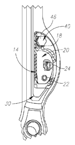
A spinal device (10) including a variable-length member (12) including a ratchet mechanism (14) that has an operative configuration that allows a change in length of the variable-length member (12) in one direction and prevents a change in length of the variable-length member (12) in an opposite direction, wherein the variable-length member (12) includes polyaxial-joint attachment members (32) for attachment to bone, which permit pivoting movement of the attachment members (32) about more than one pivoting axis, characterised by a force applicator (40) operative to adjust or advance the ratchet mechanism (14).


French Abstract

L'invention concerne un dispositif rachidien (10) comprenant un élément de longueur variable (12) qui présente un mécanisme à crémaillère (14) dont la configuration fonctionnelle permet de modifier la longueur de l'élément de longueur variable (12) dans un sens et empêche de modifier la longueur de l'élément de longueur variable (12) dans l'autre sens, lequel élément de longueur variable (12) comprend des éléments de fixation à l'articulation polyaxiale (32) permettant une fixation osseuse, lesquels éléments de fixation (32) peuvent pivoter autour de plus d'un axe de pivot, le dispositif étant caractérisé par un applicateur de force (40) actionné pour ajuster ou faire avancer le mécanisme à crémaillère (14).

Claims

Note: Claims are shown in the official language in which they were submitted.


5

CLAIMS

What is claimed is:

1. A system comprising at least one spinal device, said at least one spinal
device
comprising:
a variable-length member comprising a ratchet mechanism that has an operative
configuration that allows a change in length of said variable-length member in
one direction and
prevents a change in length of said variable-length member in an opposite
direction, wherein said
variable-length member comprises polyaxial-joint attachment members for
attachment to bone,
which permit pivoting movement of said attachment members about more than one
pivoting axis,
and
a force applicator operative to adjust or advance said ratchet mechanism,
wherein said
force applicator comprises a cam which has a tooth that engages a ratchet rack
of said ratchet
mechanism, and wherein by turning said cam, said tooth of said earn forcefully
moves said
ratchet rack so that a tooth of said ratchet rack, in which a pawl of said
ratchet mechanism is
engaged, moves out of engagement with said pawl and another tooth of said
ratchet rack moves
into engagement with said pawl.
2. The system according to claim 1, wherein said at least one spinal device
comprises a pair
of said spinal devices and a connector assembly that forms a jointed
connection between said
pair of spinal devices that permits multiple degree-of-freedom movement of
said pair of spinal
devices
3. The system according to claim 2, further comprising a connector assembly
that forms a
jointed connection between said variable-length members that permits multiple
degree-of-
freedom movement of said variable-length members
4. The system according to claim 3, wherein said connector assembly
comprises a bolt
which passes through a first hinge member and a second hinge member adjacent
said first hinge
member, and pivot pins that pivotally connect said spinal devices to said
first hinge member and
said second hinge member.
5. The system according to claim 4, wherein said connector assembly permits
rotation about
a longitudinal axis of said bolt, and independently about a longitudinal axis
of each pivot pin,
which are perpendicular to the longitudinal axis of said bolt.


6

6 The
system according to claim 1, wherein said cam of said force applicator
comprises a
head configured for turning with a tool.

Description

Note: Descriptions are shown in the official language in which they were submitted.


CA 02862827 2014-07-02
WO 2013/106262 PCT/US2013/020453
1
RATCHETED SPINAL DEVICES
FIELD OF THE INVENTION
The present invention relates generally to spinal implants and prostheses, and

particularly to spinal implants having ratchet mechanisms, such as a spinal
implant with
joints that permit movement in different degrees of freedom, or a spinal
implant with a
force applicator to control a ratchet mechanism.
BACKGROUND OF THE INVENTION
Scoliosis is a spinal deformity affecting many people. Current surgical
treatment
involves affixing long fusion rods to the spine by pedicle screws. The rod
system is
intended to force the deformed spine into a more healthy position. Other
spinal disorders
which are often treated by fusion include hyperkyphosis and hyperlordosis.
As an alternative to fusion, PCT Patent Application PCT/US2011/035278 of the
same inventor describes improved spinal devices that can be lengthened or
shortened
using a ratchet mechanism. The devices have a variable-length member that can
be
connected to standard pedicle screws as well as to other spinal rods, using
appropriate
connectors.
SUMMARY OF THE INVENTION
The present invention seeks to provide further improved spinal devices.
In one embodiment, the spinal device is in the form of a spinal rod (the term
rod,
or rod assembly, refers to one or more elongate components that together
function as a
rod and which do not necessarily have a cylindrical shape but can also be bars
and other
shapes) that can be lengthened or shortened using a ratchet mechanism. The rod
is a
variable-length member that can be connected to standard pedicle screws as
well as to
other spinal rods, using appropriate connectors. The variable-length member
can also be
directly connected to, or be supported by, bony elements of the spine.
In one embodiment of the invention, the device can be set to three different
configurations:
a. Ratchet mechanism active and the variable-length member (rod) can change in

length (extend or contract) in one direction.
b. Ratchet mechanism not active and the variable-length member can move in
opposite directions corresponding to the extending and contracting directions.
c. Locked position, wherein the length of the variable-length member is fixed.
In an embodiment of the invention, the selection of these configurations can
be
done by rotating an internal element of the assembly. For example, the
rotation of the

CA 02862827 2014-07-02
WO 2013/106262 PCT/US2013/020453
2
internal element can be done using a worm gear mechanism. The worm gear can be

activated by a shaft, through a percutaneous procedure or by an implantable
mechanism
such as an electric motor, magnet arrangement or other means known to those
skilled in
the art.
In another embodiment of the present invention, the variable-length member can

have two portions with different rigidity. For example, the variable-length
member can
have a flexible portion (e.g., when the ratchet is built such that the rod can
be only
shortened) like a flexible cable, a rope, a flexible mechanical joint and
other means
known to those skilled in the art.
In another embodiment of the invention, useful when the rod is supported
directly
by bone structure of the spine, the hook holding against the bone can have a
second hook
to fix it to the optimal position.
BRIEF DESCRIPTION OF DRAWINGS
The present invention will be understood and appreciated more fully from the
following detailed description, taken in conjunction with the drawings in
which:
Fig. 1 is a simplified pictorial illustration of a ratcheted spinal device,
constructed
and operative in accordance with a non-limiting embodiment of the invention;
Fig. 2 is a simplified pictorial illustration of a ratchet mechanism of the
ratcheted
spinal device of Fig. 1;
Fig. 3 is a simplified illustration of a force applicator that can adjust or
advance
the ratchet mechanism of the ratcheted spinal device of Fig. 1;
Fig. 4 is a simplified pictorial illustration of a spinal device, including
two rod
assemblies that are connected between three vertebrae with three bone screws,
constructed and operative in accordance with a non-limiting embodiment of the
present
invention, wherein there are connector assemblies that permit multiple degree-
of-freedom
movement;
Fig. 5 is a simplified top view illustration of one preferred embodiment of
the
connector assembly, in accordance with an embodiment of the present invention;
Fig. 6A is a simplified cross-sectional illustration of the embodiment of Fig.
5;
and
Fig. 6B is a simplified cross-sectional illustration of a modified version of
the
embodiment of Fig. 5.
DETAILED DESCRIPTION OF EMBODIMENTS

CA 02862827 2014-07-02
WO 2013/106262 PCT/US2013/020453
3
Reference is now made to Figs. 1-3, which illustrates a ratcheted spinal
device 10,
constructed and operative in accordance with another non-limiting embodiment
of the
invention.
The ratcheted spinal device 10 includes a variable-length member 12. In the
illustrated embodiment, the variable-length member 12 is a rod. The term "rod"

encompasses any slender element of any size and cross-sectional shape, such as
but not
limited to, a rod, bar, wire and the like.
As similarly described in PCT Patent Application PCT/US2011/035278, spinal
device 10 includes a ratchet mechanism 14 (Fig. 2), which has an operative
configuration
that allows a change in length of variable-length member 12 in one direction
and prevents
a change in length of the variable-length member 12 in an opposite direction.
Ratchet
mechanism 14 has ratchet teeth 16 (Fig. 3; also called ratchet rack 16) formed
along an
axial portion of variable-length member 12, and a pawl 18 (Figs. 2-3) arranged
to catch
on one of the teeth 16. Pawl 18 extends from a controller element 20 (Fig. 2)
mounted
about a pivot 22 (Fig. 2) and provided with an eccentric cam 24 (Figs. 2-3).
Rotation of
eccentric cam 24 moves pawl 18 to one of three positions: a) in ratchet
engagement with
teeth 16 so that variable-length member 12 can incrementally move in one
direction, b) in
locked engagement with teeth 16 so that variable-length member 12 cannot move
at all,
and c) moved out of engagement with teeth 16 so that variable-length member 12
can
move in both directions freely.
As seen in Fig. 1, one end 23 of variable-length member 12 is arranged to
linearly
move through an aperture 28 formed in a housing 30. Variable-length member 12
includes two polyaxial-joint attachment members 32. Both polyaxial-joint
attachment
members 32 are used to attach device 10 to available bone structure of the
spine.
In contradistinction to PCT Patent Application PCT/US2011/035278, in the
present invention, spinal device 10 includes a force applicator 40 to control
ratchet
mechanism 14. Force applicator 40 includes, without limitation, a cam 42 which
has a
tooth 44 (Fig. 3). The head 46 of cam 42 is shown in Fig. 2 (e.g., hexagonal
head); head
46 is not shown for simplicity in Fig. 3. By turning head 46 with a suitable
tool, such as a
wrench (not shown), in the clockwise direction of Fig. 3, the tooth 44 of cam
42
forcefully moves ratchet rack 16 (upwards in the sense of Fig. 3), so that the
tooth in
which pawl 18 is engaged moves out of engagement with pawl 18 and the next
lower
tooth of ratchet rack 16 moves into engagement with pawl 18. Accordingly,
force
applicator 40 adjusts or advances the ratchet mechanism 14.

CA 02862827 2014-07-02
WO 2013/106262 PCT/US2013/020453
4
Reference is now made to Fig. 4, which illustrates a spinal device 50, in
accordance with an embodiment of the present invention.
In the illustrated embodiment, spinal device 50 includes two rod assemblies 52

that are connected between three vertebrae 49 with three bone screws 54. The
rod
assemblies 52 may be constructed, without limitation, as ratcheted spinal
devices 10 or
other spinal devices. Connector assemblies 56 form jointed connections between
rod
assemblies 52. Connector assemblies 56 permit multiple degree-of-freedom
movement of
rod assemblies 52 (e.g., variable-length members 12), as will be explained
below.
It is noted that any number of vertebrae can be selected, since the design of
the
system is modular. It is also noted that the middle jointed connection of the
two rod
assemblies 52 does not have to be connected to any vertebra, meaning one or
more
vertebrae can be skipped, depending on the application. In the drawing figure,
bone
screws 54 are inserted in the pedicles, but other insertion locations can be
used.
Reference is now made to Figs. 5 and 6A, which illustrate one preferred
embodiment of the connector assembly 56, in accordance with an embodiment of
the
present invention.
Connector assembly 56 includes a bolt 58 (e.g., a central threaded bolt)
having a
head 60, and which passes through a hole formed in a first hinge member 62 and
a second
hinge member 64, which may lie on top of, or be adjacent to, first hinge
member 62. Each
hinge member is formed with a receiver 66 (Fig. 6A) for receiving therein a
pivot pin 68
(Fig. 5). One of the pivot pins 68 is pivotally received in an end 70 of one
of the rod
assemblies 52, and the other pivot pin 68 is pivotally received in an end 72
of another of
the rod assemblies 52 (Fig. 5). Thus adjacent rod assemblies 52 can pivot with
respect to
one another by means of connector assembly 56. A locking element 74 (such as a
nut)
secures pins 68 in place (Fig. 6A). Another locking element 76 (such as a nut)
is threaded
on the end of threaded bolt 58 to complete the assembly (Fig. 6A).
Fig. 6B illustrates a variation of the embodiment of Fig. 6A. Like elements
are
designated by like numerals. The main differences are the shape of locking
element 74
and the receiver 66 of the first hinge member 62 has a closed aperture instead
of the open
aperture of Fig. 6A. Other variations are also possible within the scope of
the invention.
Connector assemblies 56 permit multiple degree-of-freedom movement of rod
assemblies 52. Rotation is permissible about the longitudinal axis of central
threaded bolt
58, and independently about the longitudinal axis of each pin 68, which are
perpendicular
to the longitudinal axis of central threaded bolt 58.

Representative Drawing
A single figure which represents the drawing illustrating the invention.
Administrative Status

For a clearer understanding of the status of the application/patent presented on this page, the site Disclaimer , as well as the definitions for Patent , Administrative Status , Maintenance Fee  and Payment History  should be consulted.

Administrative Status

Title Date
Forecasted Issue Date 2019-03-19
(86) PCT Filing Date 2013-01-07
(87) PCT Publication Date 2013-07-18
(85) National Entry 2014-07-02
Examination Requested 2017-09-25
(45) Issued 2019-03-19

Abandonment History

There is no abandonment history.

Maintenance Fee

Last Payment of $263.14 was received on 2023-12-18


 Upcoming maintenance fee amounts

Description Date Amount
Next Payment if small entity fee 2025-01-07 $125.00
Next Payment if standard fee 2025-01-07 $347.00

Note : If the full payment has not been received on or before the date indicated, a further fee may be required which may be one of the following

  • the reinstatement fee;
  • the late payment fee; or
  • additional fee to reverse deemed expiry.

Patent fees are adjusted on the 1st of January every year. The amounts above are the current amounts if received by December 31 of the current year.
Please refer to the CIPO Patent Fees web page to see all current fee amounts.

Payment History

Fee Type Anniversary Year Due Date Amount Paid Paid Date
Application Fee $400.00 2014-07-02
Registration of a document - section 124 $100.00 2014-10-07
Maintenance Fee - Application - New Act 2 2015-01-07 $100.00 2014-12-30
Maintenance Fee - Application - New Act 3 2016-01-07 $100.00 2015-12-23
Maintenance Fee - Application - New Act 4 2017-01-09 $100.00 2016-12-29
Request for Examination $800.00 2017-09-25
Maintenance Fee - Application - New Act 5 2018-01-08 $200.00 2017-11-21
Maintenance Fee - Application - New Act 6 2019-01-07 $200.00 2018-11-28
Final Fee $300.00 2019-01-30
Maintenance Fee - Patent - New Act 7 2020-01-07 $200.00 2020-01-06
Maintenance Fee - Patent - New Act 8 2021-01-07 $200.00 2020-12-30
Maintenance Fee - Patent - New Act 9 2022-01-07 $203.59 2022-01-04
Maintenance Fee - Patent - New Act 10 2023-01-09 $254.49 2022-12-22
Maintenance Fee - Patent - New Act 11 2024-01-08 $263.14 2023-12-18
Owners on Record

Note: Records showing the ownership history in alphabetical order.

Current Owners on Record
APIFIX LTD.
Past Owners on Record
None
Past Owners that do not appear in the "Owners on Record" listing will appear in other documentation within the application.
Documents

To view selected files, please enter reCAPTCHA code :


To view images, click a link in the Document Description column. To download the documents, select one or more checkboxes in the first column and then click the "Download Selected in PDF format (Zip Archive)" or the "Download Selected as Single PDF" button.

List of published and non-published patent-specific documents on the CPD .

If you have any difficulty accessing content, you can call the Client Service Centre at 1-866-997-1936 or send them an e-mail at CIPO Client Service Centre.


Document
Description 
Date
(yyyy-mm-dd) 
Number of pages   Size of Image (KB) 
Abstract 2014-07-02 2 68
Claims 2014-07-02 2 59
Drawings 2014-07-02 4 76
Description 2014-07-02 4 218
Representative Drawing 2014-09-19 1 6
Cover Page 2014-10-14 2 40
Request for Examination 2017-09-25 3 87
Maintenance Fee Payment 2017-11-21 1 33
Examiner Requisition 2018-05-11 3 148
Amendment 2018-11-07 5 140
Claims 2018-11-07 2 50
Final Fee 2019-01-30 3 85
Representative Drawing 2019-02-15 1 7
Cover Page 2019-02-15 2 40
PCT 2014-07-02 4 122
Assignment 2014-07-02 7 270
Assignment 2014-10-07 5 165
Fees 2014-12-30 1 33
Fees 2015-12-23 1 33
Correspondence 2016-09-23 10 638
Correspondence 2016-10-24 10 534
Office Letter 2016-11-04 1 37
Office Letter 2016-11-15 9 1,362
Fees 2016-12-29 1 33
Office Letter 2017-02-10 1 30