Note: Descriptions are shown in the official language in which they were submitted.
CA 02862857 2014-07-08
WO 2013/165255 PCT/N02013/050073
AN EXPANSION CONTROL DEVICE FOR A PACKER BODY AND ALSO A PIPING TOOL,
METHOD AND USE FOR CONTROLLING THE EXPANSION OF THE PACKER BODY
Field of the invention
The present invention relates to a device for controlling the expansion of a
packer
s body, for example a sleeve-shaped packer body, which is arranged on a
pipe stem (a
mandrel). Depending on the relevant application, the mandrel may be hollow or
solid.
The invention also relates to a piping tool, a method and applications for
controlling
the expansion of said packer body by means of such an expansion-control
device.
A packer body like that must be compressible axially, that is to say in the
longitudinal
io direction of the mandrel, and will typically be formed from an
elastic/plastic material
of a suitable type, for example from rubber, elastomer material and/or
plastics mate-
rial. As an alternative or addition, even other materials and/or different
material quali-
ties may be used if appropriate.
The packer body is generally used in connection with pipe plugs, piping tools
and the
is like, in order to provide a pressure-tight connection against a
separate, tubular body,
possibly against a surrounding hole wall, as the packer body is being
compressed and
expanded against the tubular body or against the hole wall. Thus, the tubular
body
may be constituted by a casing in a well, for example a production tubing, a
pipeline
on a sea floor or on the surface, a pipe in a processing plant or other plant,
or a tubu-
zo lar body in any other connection above or under water. Said hole wall
may generally
define any hole, for example a borehole in the underground or some other type
of hole
in any medium.
The packer body may thus be used in connection with, for example, a downhole
plug,
a well tool, a pressure-testing plug or an anchoring means. Such an anchoring
means
zs is often used in combination with such a plug or tool. This anchoring
body may be
formed as a gripping jaw, a gripping wedge, gripping claw, gripping die or a
similar
CA 02862857 2014-07-08
WO 2013/165255 PCT/N02013/050073
2
structure provided with hooks, teeth, claws or the like for engagement with
said tubu-
lar body or hole wall.
Moreover, the packer body may be arranged for expansion radially outwards or
radial-
ly inwards seen relative to the mandrel on which the packer body is arranged.
Howev-
s er, inward radial expansion is conditional on the mandrel being hollow.
Background of the invention
The invention has its background in problems associated with known structures
and
methods of expanding, setting, fixing and/or loosening such a packer body
relative to
an external object, for example a tubular body or a hole wall. It is in
particular a ques-
io tion of problems that may arise when the packer body is subjected to
great stresses
during setting and/or use, for example great axial forces, high pressure, high
temper-
ature, erosive particles and/or a chemically aggressive environment. Such
conditions
may arise, for example, when the packer body is used in connection with an
under-
ground well at sea or on shore, for example in a petroleum well.
is Under such extreme conditions, the elastic/plastic packer body may,
inter alia, extrude
or flow into accessible cavities in the proximity of the packer body, for
example into
cavities in the proximity of the packer body lengthways and/or widthways. Such
ex-
trusion is normally the more pronounced the larger the expansion and/or
stresses to
which the packer body is subjected during setting and/or use. As a rule, this
extrusion
zo is undesired and may weaken, possibly completely or partially ruin, the
packer body.
This may entail, inter alia, poor sealing function during use, possibly the
packer body
sticking completely to, possibly wedging against, said external object. It may
thereby
be difficult to loosen the packer body after use, the packer body possibly
also getting
torn to pieces and becoming ruined by such loosening. In a subterranean well,
such a
zs weakened packer body may constitute an incomplete pressure barrier which
is possi-
bly associated with pressure/fluid leakage and poor pressure control.
Another property of such an elastic/plastic packer body is that when the
packer body
is being compressed, expanded and set/used, energy is being stored in it. It
is this
stored energy that provides for the packer body to be pressed sealingly
against said
30 external object. However, the extreme conditions mentioned may result in
the packer
body disintegrating, eroding or being crushed into pieces, so that the packer
body un-
intentionally loosens.
There is thus a need in the industry for devices that prevent extrusion and/or
disinte-
gration of such a packer body during setting and/or use.
CA 02862857 2014-07-08
WO 2013/165255 PCT/N02013/050073
3
The prior art and its drawbacks
To remedy the problem of undesired extrusion of said packer body during
setting
and/or use, the prior art includes several patent publications that disclose
various so-
called anti-extrusion devices.
s As close patent publications, the following publications are mentioned:
- US 3061012 A;
- US 6,318,461 B1;
- WO 2011/037581 A;
- US 7,178,602 B2, corresponding to NO 318363 B1; and
lo - US 7,290,603 B2, corresponding to NO 321083 B3.
All these publications disclose variants of such anti-extrusion devices that
in actual
fact relate to expansion-control mechanisms for associated packer bodies. Each
such
expansion-control mechanism provides for controlling the radial expansion of
the
packer body during its compression and setting against an external object, for
exam-
is against a pipe. The expansion-control mechanism also provides for the
packer
body to be held in place within a defined area during use.
Furthermore, each such known expansion-control mechanism includes several
individ-
ual and overlapping screen elements which can be moved radially outwards, and
which together may form an annular and supporting screen against an axially
adjacent
zo packer body. In the passive position, the screen elements are retracted,
lying more or
less parallel to the longitudinal direction of the mechanism. Activation of
the screen
elements is typically performed by subjecting them to an axial push force from
an as-
sociated activation device. Such an activation device may be constituted by,
for exam-
ple, an actuator, a driving motor, a hydraulic piston, a separate running tool
or a pip-
25 ing tool, for example a pipe plug with anchoring bodies, which is
connected to the
expansion-control mechanism. During activation, all the screen elements are
moved
radially outwards into an expanded position, in which, together and in an
overlapping
configuration, they form said annular and supporting screen against the packer
body.
The screen is also formed to rest against said external object, for example a
pipe.
30 Said US 3061012 A appears to represent the closest prior art. The
publication disclos-
es such an annular and supporting screen. Each screen element of the screen is
ar-
ranged to rotate around an inner element portion and thereby tilt an opposite
outer
element portion out radially when a push force is supplied to the inner
element por-
tion. The outer element portion is formed with a chamfered face, abutting,
when in the
CA 02862857 2014-07-08
WO 2013/165255 PCT/N02013/050073
4
expanded position, against the packer body and supporting it together with
other
screen elements of the screen.
US 6,318,461 B1, WO 2011/037581A and US 7,178,602 B2 disclose plug devices,
each plug device of which includes such an annular and supporting screen for
an adja-
s cent packer body. Each screen element of the screen is connected to an
expansion-
control mechanism which includes, inter alia, two movable members that are
rotatably
connected to each other. At its free end, one member is movably connected to,
or
formed as, a screen element of the screen, whereas the free end of the second
mem-
ber is movably connected to an axially movable activation device. When the
activation
lo device supplies an axial push force to the second member, both members
are tilted
outwards, rotating relative to each other. In this way, all screen elements
are activat-
ed and may position themselves as a supporting screen against the packer
element.
US 7,290,603 B2 also deals with a plug device including such an annular and
support-
ing screen for an adjacent packer body. Each screen element of the screen is
connect-
is ed to an axially movable pressure element. As the pressure element
supplies an axial
push force to the screen element, the screen element is pushed onto a conical
thrust
collar which is arranged adjacent to the packer body, and which is sloping
towards the
screen element. The screen element may thereby be pushed further in the radial
di-
rection outwards. In this way, all the screen elements are activated and may
position
20 themselves as a supporting screen against the packer body.
The anti-extrusion devices according to the above-mentioned prior art may be
encum-
bered with various drawbacks. Thus, it may be a question of relatively great
technical
complexity and/or lack of flexibility as far as the structure and/or operation
are/is con-
cerned, possibly lack of reliability and/or effectiveness, and/or technical
limitations of
zs various components and equipment forming part of the specific device.
As examples of such drawbacks, both US 6,318,461 B1, WO 2011/037581 A and US
7,178,602 B2 describe relatively complex anti-extrusion devices. Besides, US
7,178,602 B2 describes a structure that entails very uneven compression of the
pack-
er body during setting, that is to say in which the radially inner portion of
the packer
30 body is compressed far more than the radially outer portion thereof.
Such uneven
compression results in, inter alia, locally high friction in and around the
packer body
and may weaken, possibly ruin, one or more portions of the packer body.
Further, several such known anti-extrusion devices are encumbered with unduly
much
friction in connection with the radial expansion and setting of the screen
elements of
CA 02862857 2014-07-08
WO 2013/165255 PCT/N02013/050073
the device against, for example, a surrounding well wall or pipe wall. In this
connec-
tion, the screen elements may scrape against the well wall/pipe wall and
create unduly
much friction. This may also lead to insufficient compressive force being
supplied to
the associated packer body for its adequate expansion and setting. This may
further
s result in incorrect setting of the anti-extrusion device and/or the
associated packer
body, for example when these have been assembled into a downhole plug. This
may
also lead to the anti-extrusion device and/or packer body becoming completely
or par-
tially ruined, so that the downhole plug will have to be replaced with a new
downhole
plug.
io Object of the invention
The supereminent objective of the invention is to remedy or reduce at least
one of the
drawbacks of the prior art in the relevant field, or at least provide a useful
alternative
to the prior art in the field.
Further, it is a primary objective of the invention to provide an expansion-
control
is mechanism which effectively prevents the extrusion of a packer body
during its ex-
pansion (cf. anti-extrusion device).
Further, it is an object to provide an expansion-control mechanism which at
least
counteracts the environmentally related disintegration of said packer body
during use.
It is also an objective to provide an expansion-control mechanism which
provides for
zo the least possible friction associated with the radial expansion and
setting of said
screen elements (hereinafter termed packer-control elements) and the packer
body
against an external object, for example a well wall or pipe wall.
Another object of the invention is to provide an expansion-control mechanism
which
has great technical flexibility with regard to its structure and operation.
25 A further object is to provide an expansion-control mechanism that leads
to the most
gentle and even compression possible of said packer body.
Yet another object is to provide an expansion-control mechanism which has
packer-
control elements whose radial travel may be individually matched in order
thereby to
compensate for any irregularities, for example restrictions, deposits or
ovality of the
30 object against which the elements are to be moved, for example against a
pipe.
Further, it is an object to provide an expansion-control mechanism that may be
used
to create a barrier against cross flow in a pipe, for example a casing in a
well.
CA 02862857 2014-07-08
WO 2013/165255 PCT/N02013/050073
6
Furthermore, it is an object to provide an expansion-control mechanism that
can be
used to create a supporting base for a fluid in a well pipe, for example for a
highly
viscous fluid, cement slurry or the like in a casing in a well.
Additional objects of the invention are to provide a piping tool, a method and
also uses
s based on such an expansion-control mechanism for a packer body, for
example a
sleeve-shaped packer body.
General description of how the objects are achieved
The objects are achieved through features as specified in the description
below and in
the claims that follow.
io According to a first aspect of the invention, an expansion-control
device is provided for
a packer body on a mandrel which is provided with a supporting ring arranged
axially
adjacent to an end of the packer body, the expansion-control device including:
- a packer-control element arranged to be placed axially adjacent to the
supporting
ring and arranged for radial movement relative to the mandrel; and
is - a power-transmission body operatively connected to the packer-control
element for
the optional transmission of activating power to the packer-control element.
What is particular about the expansion-control device is that said power-
transmission
body includes a lever body with (a) a fulcrum portion and (b) a lever arm that
projects
radially from the fulcrum portion;
zo - that the free end of the lever arm is operatively connected to the
packer-control el-
ement;
- that the lever body is rotatable around an axis of rotation through said
fulcrum por-
tion, whereby the lever arm is rotatable around the axis of rotation as well;
and
- that the power-transmission body also includes a torque-supplying device
to which
25 the lever body is operatively connected for the optional supply of a
torque to the lever
body, and for the associated rotation of the lever body around the axis of
rotation. The
free end of the lever arm and the packer-control element are thereby arranged
to be
moved radially relative to the mandrel.
As mentioned, the packer body must be axially compressible, that is to say in
the Ion-
30 gitudinal direction of the mandrel, in order thereby to be expanded
radially relative to
the mandrel. Such a packer body will typically be sleeve-shaped, but other
suitable
packer types may be used as well. Further, the packer body may be formed from
an
elastic/plastic material, for example from rubber, elastomer material,
plastics material
and/or from other suitable materials if appropriate. The packer body may
possibly be
CA 02862857 2014-07-08
WO 2013/165255 PCT/N02013/050073
7
constituted by a compound packer body including two or more packer elements
that
are arranged on said mandrel with possible separating bodies between them.
Such
packer elements may be arranged axially and/or radially adjacent to each
other, that
is to say axially following and/or radially onlapping each other. Thus, for
example, a
s compound packer body including three sleeve-shaped and axially successive
packer
elements with metallic separating rings between them may be used. The two
packer
elements arranged at the end portions of the packer body are formed from
relatively
hard rubber or elastomer material, whereas the intermediate packer element is
formed from softer rubber or elastomer material. As the packer body is being
com-
ic) pressed, the two outer and harder packer elements will provide for a
controlled radial
expansion of the intermediate and softer packer element against an external
object,
for example a pipe wall or a hole wall, in order finally to form an effective
seal against
the external object.
Furthermore, the packer-control element in question may have a configuration
as
is shown in the following exemplary embodiment, but any other appropriate
configura-
tion may be used as well. In this connection, the packer-control element is
preferably
arranged to cooperate with one or more separate and at least partially
overlapping
packer-control elements to form, all together, in the operative position, a
supporting
screen against the adjacent supporting ring and the adjacent packer body, as
de-
20 scribed above in connection with said prior-art screen elements. This
screen of packer-
control elements is preferably annular and continuous.
Thus, adjacent and overlapping packer-control elements in the screen may have
con-
tact areas of complementary designs. Neighbouring packer-control elements
prefera-
bly have a sufficiently large overlap for the overlap to be maintained all the
time when
zs the screen is being activated and expanded in both the radial and the
circumferential
directions. Examples of such screens with expandable, complementary and
overlap-
ping packer-control elements (screen elements) are shown in US 3061012 A, in
WO
2011/037581 A, in US 7,178,602 B2 and in US 7,290,603 B2, among other docu-
ments; cf. the above discussion of the prior art.
30 Cooperating packer-control elements that are to form such a supporting
screen may
also be arranged axially adjacent to said supporting ring on a portion of said
mandrel,
for example on a fixed end portion of the mandrel. As an alternative, such
cooperating
packer-control elements may be arranged axially adjacent to said supporting
ring and
be supported and carried on a supporting sleeve extending axially, which is
connected
35 to the supporting ring. Such a supporting sleeve is preferably arranged
in an axially
CA 02862857 2014-07-08
WO 2013/165255 PCT/N02013/050073
8
movable manner on the mandrel.
In addition, said supporting ring and/or supporting sleeve may be provided or
formed
with suitable guiding elements, for example guiding grooves, guide edges,
guide rails,
guide rods, recesses or the like, providing for the cooperating packer-control
elements
s to be guided in the radial direction during their activation.
Besides, the lever body of the expansion-control device may have an axis of
rotation
which is arranged to extend in a circumferential direction relative to the
mandrel.
Thus, the axis of rotation may be arranged to extend, in the main,
perpendicularly to
the axial direction of the mandrel.
lo According to a first embodiment of the expansion-control device, the
free end of the
lever arm may be movably connected to the packer-control element.
In a first variant of this first embodiment, the free end of the lever arm may
include a
first pivot head which is rotatably connected to the packer-control element.
Thus, the
first pivot head may be rotatably arranged in a corresponding recess in the
packer-
is control element.
In a second variant of this first embodiment, the free end of the lever arm
may include
a toothed cam or arch in movable engagement with a corresponding toothed
portion
of the packer-control element. Thus, the packer-control element may include a
pitch
rack which includes said corresponding toothed portion of the packer-control
element.
20 According to a second embodiment of the expansion-control device, said
torque-
supplying device may include a rotary motor, for example a reversible rotary
motor, to
which the lever body is rotatably connected, for the optional supply of a
torque to the
lever body, the rotary motor constituting an activating device for the
expansion-
control device. If reversible, the rotary motor may be used to activate and
push out
25 the associated packer-control element of said screen of such elements,
and subse-
quently to deactivate and retract the packer-control element when, possibly,
neces-
sary. Thus, the rotary motor may be constituted by an electromotor, a
hydraulic motor
or a pneumatic motor.
According to an alternative, third embodiment of the expansion-control device,
torque-
30 supplying device may include:
- a torque arm projecting radially from the fulcrum portion in a direction
not coinciding
with the radial direction of the lever arm out from the fulcrum portion; and
- a driving body which is movably connected to the free end of the lever
arm for the
CA 02862857 2014-07-08
WO 2013/165255 PCT/N02013/050073
9
optional supply of a torque-generating driving force to the lever body. This
driving
body is arranged to be connected to an activation device for the expansion-
control
device.
In a first variant of this third embodiment, the driving body may be arranged
in an
s axially movable manner, wherein the free end of the torque arm includes a
second
pivot head which is rotatably connected to the axially movable driving body.
Thus, the
second pivot head may be rotatably arranged in a corresponding recess in the
axially
movable driving body. As an alternative or addition, the axially movable
driving body
may include a plunger, a rod, for example a push rod, a piston or the like.
io In a second variant of this third embodiment, the driving body may be
arranged in an
axially movable manner, wherein the free end of the torque arm includes a
toothed
cam or arch in movable engagement with in a corresponding toothed portion of
the
axially movable driving body. Thus, the axially movable driving body may
include a
pitch rack which includes said corresponding toothed portion on the driving
body.
is According to the first or second variant of the third embodiment, the
axially movable
driving body may be spring-loaded for matched axial movement of the driving
body
and thereby for matched radial movement of the packer-control element. The
radial
travel of the packer-control element may be matched to compensate for any
irregular-
ities, for example restrictions, deposits or ova lity, of the object against
which the ele-
20 ment is to be moved.
According to the first or second variant of the third embodiment, and as an
alternative
or addition, the axially movable driving body may be arranged to be
connectable to an
axially movable activation device for the expansion-control device. Thus, the
axially
movable activation device may include one of an actuator and a pusher.
Further, the
25 axially movable activation device may be mechanically activated,
electrically activated,
hydraulically activated and/or pneumatically activate.
In a third variant of this third embodiment, the driving body may include a
rotatable
worm screw, wherein the free end of the torque arm includes a toothed cam or
arch
which is rotatably engaged in the worm screw. The rotatable worm screw may
thus be
30 connected to a torque limiter for the matched supply of torque to the
worm screw, and
thereby for the matched radial movement of the packer-control element. The
radial
travel of the packer-control element may thereby be matched to possibly
compensate
for any irregularities on the object against which the element is to be moved.
The
torque limiter may include, for example, a spring-loaded ratchet device of a
known
CA 02862857 2014-07-08
WO 2013/165255 PCT/N02013/050073
type.
As an alternative or addition, the driving body may be arranged to be
connectable to a
rotatable activation device for the expansion-control device. Thus, the
rotatable acti-
vation device may include a rotary motor, for example a reversible rotary
motor. This
s rotary motor may be constituted by an electromotor, a hydraulic motor or
a pneumatic
motor.
According to this third embodiment, seen relative to the position of the
mandrel, the
free end of the torque arm may be arranged on the inside of the rotational
axis of the
lever body. An axial push force supplied by the driving body to the free end
of the
io torque arm will thereby supply a torque that lifts the free end of the
lever arm away
from the mandrel, thus moving the packer-control element radially away from
the
mandrel.
As an alternative to the latter embodiment variant, the free end of the torque
arm,
seen relative to the position of the mandrel, may be arranged on the outside
of the
is rotational axis of the lever body. An axial pull force supplied by the
driving body to the
free end of the torque arm, will thus supply a torque that lifts the free end
of the lever
arm away from the mandrel, thus moving the packer-control element radially
away
from the mandrel.
According to a fourth embodiment of the expansion-control device, said lever
body
zo may be formed by a toothed wheel which is rotatable around said
rotational axis,
wherein a first circular sector of the toothed wheel constitutes said lever
arm and in-
cludes a circumferential first toothed portion which is in movable engagement
with a
corresponding toothed portion on the packer-control element. Thus, the packer-
control
element may include a pitch rack which includes said corresponding toothed
portion of
25 the packer-control element.
In a first variant of this fourth embodiment, said torque-supplying device may
include
a rotary motor, for example a reversible rotary motor, to which the toothed
wheel is
rotatably connected, for the optional supply of torque to the toothed wheel,
the rotary
motor constituting an activation device for the expansion-control device. The
rotary
30 motor may thus be constituted by one of an electromotor, a hydraulic
motor and a
pneumatic motor.
In a second variant of this fourth embodiment, the torque-supplying device may
in-
clude:
- a second circular sector of the toothed wheel, which forms a torque arm and
includes
CA 02862857 2014-07-08
WO 2013/165255 PCT/N02013/050073
11
a circumferential second toothed portion; and
- a driving body with a corresponding toothed portion which is in movable
engagement
with the circumferential second toothed portion of the toothed wheel. This
driving
body is arranged to be connectable to an activation device for the expansion-
control
device.
The driving body may thus be arranged to be axially movable. This axially
movable
driving body may include a pitch rack which includes the corresponding toothed
por-
tion of the driving body. As an alternative or addition, the axially movable
driving body
may be spring-loaded for matched axial movement of the driving body, and
thereby
io for matched radial movement of the packer-control element. The radial
travel of the
packer-control element may thereby be matched in order, possibly, to
compensate for
any irregularities on the object against which the element is to be moved.
As an alternative, the driving body may include a rotatable worm screw which
is rotat-
ably engaged in the circumferential second toothed portion of the toothed
wheel. This
is rotatable worm screw may be connected to a torque limiter for a matched
supply of
torque to the worm screw, and thereby for a matched radial movement of the
packer-
control element. The radial travel of the packer-control element may thereby
be
matched to possibly compensate for any irregularities on the object against
which the
element is to be moved. The torque limiter may include, for example, a spring-
loaded
20 ratchet device of a known type.
Further, the driving body may be arranged to be connectable to a rotatable
activation
device for the expansion-control device. This rotatable activation device may
include a
rotary motor, for example a reversible rotary motor. Further, the rotary motor
may be
constituted by an electromotor, a hydraulic motor or a pneumatic motor.
25 According to a second aspect of the invention, a piping tool with
expansion-control
function for a packer is provided as well, the tool including:
- a mandrel;
- a packer body arranged on the mandrel;
- a first supporting ring arranged axially adjacent to a first end of the
packer body;
30 - a second supporting ring arranged axially adjacent to a second end of
the packer
body; and
- an annular assembly of at least two radially movable packer-control
elements ar-
ranged axially adjacent to at least one of the first supporting ring and the
second sup-
porting ring;
35 - at least one of the first supporting ring and the second supporting
ring being axially
CA 02862857 2014-07-08
WO 2013/165255 PCT/N02013/050073
12
movably arranged on the mandrel; and
- the at least one axially movable supporting ring being provided with an
annular as-
sembly which is also axially movably arranged on the mandrel.
What is particular about the piping tool is that each of said packer-control
elements
s constitutes part of in an expansion-control device according to the first
aspect of the
invention.
Thus, one or both of the support rings may be axially movably arranged on the
man-
drel.
As mentioned above, said packer body will typically be sleeve-shaped, but
other sulta-
n ble packer types may be used as well.
Further, in the operative position, said annular assembly of packer-control
elements is
arranged to form a supporting screen against one of said adjacent supporting
rings
and the adjacent packer body, as described above. This annular assembly
(screen)
preferably has overlapping packer-control elements and is thereby continuous.
is Furthermore, cooperating packer-control elements that are to form such a
supporting
screen may be arranged axially adjacent to said supporting ring on a portion
of said
mandrel, for example on a fixed end portion of the mandrel. As an alternative,
such
cooperating packer-control elements may be arranged axially adjacent to said
sup-
porting ring and be carried on a supporting sleeve extending axially, which is
connect-
20 ed to the supporting ring. Preferably, such a supporting sleeve is
axially movably ar-
ranged on the mandrel.
In addition, said supporting ring and/or supporting sleeve may be provided or
formed
with suitable guiding elements, for example guiding grooves, guide edges,
guide rails,
guide rods, guide projections, recesses or the like, which provide for the
cooperating
25 packer-control elements to be guided in the radial direction during
their activation.
For further details and comments concerning said expansion-control device,
reference
is made to the preceding discussion of the first aspect of the invention and
the de-
scription of an exemplary embodiment of the invention below.
Moreover, an annular assembly of at least two radially movable packer-control
ele-
30 ments may be arranged axially adjacent to just one of the first
supporting ring and the
second supporting ring.
As an alternative, an annular assembly of at least two radially movable packer-
control
CA 02862857 2014-07-08
WO 2013/165255 PCT/N02013/050073
13
elements may be arranged axially adjacent to both the first supporting ring
and the
second supporting ring.
Further, at least the lever body and the torque-supplying device of the
expansion-
control device may be arranged in a tubular power-transmission housing which
is con-
nected to the mandrel. Thus, the lever body may be provided with a rotary axle
which
is rotatable around the rotational axis of the lever body, and which is
supported in the
tubular power-transmission housing.
Furthermore, the lever body may be arranged in an axial recess in the tubular
power-
transmission housing or, alternatively, in an axial bore in the tubular power-
io transmission housing. As an alternative or addition, the torque-
supplying device may
be arranged in an axial recess in the tubular power-transmission housing or,
alterna-
tively, in an axial bore in the tubular power-transmission housing.
As an alternative or addition, said at least one axially movable assembly may
be con-
nected to at least one activation device for the optional supply of activating
power to
is the power-transmitting bodies of the expansion-control device.
In this connection, said at least one activation device may include at least
one of an
axially movable activation device and a rotatable activation device. Thus,
such an axi-
ally movable activation device may include one of an actuator and a pusher,
whereas
such a rotatable activation device may include a rotary motor. Further, the
activation
zo device may be mechanically activated, electrically activated,
hydraulically activated
and/or pneumatically activated.
Besides, when arranged in a tubular power-transmission housing, the lever body
and
torque-supplying device of the expansion-control device, possibly said
activation de-
vice as well, may be protectively arranged under at least one suitable cover,
for ex-
25 ample a sleeve-shaped cover surrounding the power-transmission housing
and its lev-
er body, torque-supplying device and possibly its activation device. During
use, this
will prevent unwanted particles and dirt from penetrating to said components,
possibly
hampering the operation thereof.
Moreover, the piping tool and/or said activation device may include at least
one lock-
30 ing device or locking mechanism, for example a releasable locking
device/locking
mechanism which provides for said annular assembly of packer-control elements
and
the packer body to be kept locked in an expanded position. In this connection,
the
piping tool and/or activation device may include, for example, suitable latch
grooves,
locking dogs, retaining rings, detention wedges, detention springs, detention
sleeves,
CA 02862857 2014-07-08
WO 2013/165255 PCT/N02013/050073
14
self-locking threads or similar locking devices/locking mechanisms.
The mandrel may also be hollow or solid, as mentioned above. However, inward
radial
expansion of the packer body is conditional on the mandrel being hollow.
According to a third aspect of the invention, a method of controlling the
expansion of a
s packer body on a mandrel is provided as well, the method including the
following
steps:
- arranging a first supporting ring and a second supporting ring axially
adjacent to,
respectively, a first end and a second end of the packer body;
- arranging an annular assembly which includes at least two radially
movable packer-
io control elements, axially adjacent to at least one of the first
supporting ring and the
second supporting ring.
What is particular about the method is that it also includes the following
steps:
- incorporating each of said packer-control elements in an expansion-
control device in
accordance with the first aspect of the invention;
is - activating at least one activation device for the expansion-control
device in order
thereby to supply a torque to said lever body, rotating the lever body around
said ro-
tational axis, whereby the free end of the lever arm and the packer-control
element
are moved radially away from the mandrel and in the direction of a tubular
object,
against which the packer body is to be set; and
zo - then sliding at least one of the first supporting ring and the second
supporting ring
against the packer-control element in order thereby to expand the packer-body
radial-
ly relative to the mandrel. Said supporting rings and said at least one
assembly of
packer-control elements thereby control the expansion of the packer body.
As mentioned above, said packer body will typically be sleeve-shaped, but
other suita-
25 ble packer types may be used as well.
Further, in the operative position, said annular assembly of packer-control
elements is
arranged to form a supporting screen against at least one of said adjacent
supporting
rings and the adjacent packer body, as described above. This annular assembly
(screen) preferably has overlapping packer-control elements and is thereby
continu-
30 ous.
For further details and comments concerning said expansion-control device,
reference
is made here as well to the preceding discussion of the first aspect of the
invention
and the description of an exemplary embodiment of the invention below.
CA 02862857 2014-07-08
WO 2013/165255 PCT/N02013/050073
According to a fourth aspect of the invention, a use of an expansion-control
device
according to the first aspect of the invention is provided as well, for
controlling the
expansion of a packer body, for example a sleeve-shaped packer body, on a
mandrel.
Finally, according to a fifth aspect of the invention, a use of a piping tool
according to
s the second aspect of the invention is provided, for controlling the
expansion of a pack-
er body, for example a sleeve-shaped packer body, on a mandrel in the piping
tool.
Brief description of the figures of the exemplary embodiment
In what follows, a non-limiting example of an embodiment of the description is
de-
scribed, wherein:
io Figures 1-5 show, respectively, a perspective drawing, a side view, a
plan view, an
end view and an opposite end view of an expansion-control device ac-
cording to the invention;
Figure 6 shows a longitudinal section through the expansion-control
device,
viewed along the cutting line VI-VI of figure 5;
is Figures 7, 8 and 9 show, respectively, a perspective drawing, a cross
section and a
longitudinal section of a piping tool according to the invention placed in
a casing, figure 9 showing a longitudinal section through the piping tool
seen along the cutting line IX-IX of figure 8, the piping tool being pro-
vided with a sleeve-shaped packer body, whose end portions are adja-
cent to expansion-control devices of the type that is shown in figures 1-
6, and figures 7-9 showing the piping tool before the expansion and set-
ting of the packer body against the casing;
Figures 10, 11 and 12 show, respectively, a perspective drawing, a cross
section and a
longitudinal section of said piping tool and casing, figure 12 showing a
longitudinal section through the piping tool and casing seen along the
cutting line XII-XII of figure 11, figures 10-12 showing the piping tool
after the activation and expansion of said expansion-control devices, but
before the expansion and setting of the packer body against the casing;
Figures 13, 14 and 15 show, respectively, a perspective drawing, a cross
section and a
longitudinal section of said piping tool and casing, figure 15 showing a
longitudinal section through the piping tool and the casing seen along
the cutting line XV-XV shown in figure 14, figures 13-15 showing the
piping tool after the activation and expansion of said expansion-control
CA 02862857 2014-07-08
WO 2013/165255 PCT/N02013/050073
16
devices, but before the expansion and setting of the packer body against
the casing, and an expansion-control device at one end portion of the
packer body having been expanded only partially against the casing be-
cause of a local restriction on the inside of the casing; and
s Figures 16, 17 and 18 show, respectively, a perspective drawing, a cross
section and a
longitudinal section of said piping tool and casing, figure 18 showing a
longitudinal section through the piping tool and the casing seen along
the cutting line XVIII-XVIII shown in figure 17, figures 16-18 showing
the piping tool after the activation and expansion of said expansion-
control devices, and after the expansion and setting of the packer body
against the casing.
The figures are somewhat schematic and show elements and details that are
essential
for the understanding of the invention. Further, the figures may be somewhat
distort-
ed with regard to the relative dimensions of the elements and details that are
shown
is in the figures. The figures may also be somewhat simplified drawings
with regard to
the design and richness in detail of such elements and details. In what
follows, some
like, equivalent or corresponding elements and details in the figures will be
indicated,
by and large, by the same reference numerals.
Detailed description of the exemplary embodiment
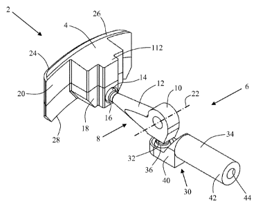
zo Figures 1-6 show an expansion-control device 2 in accordance with the
invention. This
expansion-control device 2 includes a packer-control element 4 and a power-
transmission body 6 which is movably connected to the packer-control element
4.
Further, the power-transmission body 6 includes, inter alia, a lever body 8
with a ful-
crum portion 10, and a lever arm 12 projecting radially from the fulcrum
portion 10.
25 In this embodiment, the free end of the lever arm 12 includes a first
pivot head 14
which is rotatably arranged in a corresponding bore 16 in a lower portion 18,
and at a
back 20, of the packer-control element 4. Further, the lever body 8 is
rotatable around
a rotational axis 22 through said fulcrum portion 10, whereby the lever arm 12
is ro-
tatable around the rotational axis 22 as well.
30 The packer-control element 4 also includes a front 24 which, in the
activated and radi-
ally expanded position and together with several cooperating and overlapping
packer-
control elements, forms an annular and supporting screen against an axially
adjacent
packer (cf. the above discussion of the prior art). The screen is also
arranged to rest
against a tubular object, for example against a casing. For this reason, the
top side 26
CA 02862857 2014-07-08
WO 2013/165255 PCT/N02013/050073
17
and the bottom side 28 of the packer-control element 4 have the shape of a
circular
arc which fits complementarily against an associated tubular body, cf. figures
4 and 5.
Furthermore, the power-transmission body 6 also includes a torque-supplying
device
30 to which the lever body 8 is operatively connected for the optional supply
of torque
s to the lever body 8, and for the associated rotation of the lever body 8
around the
rotational axis 22. In this embodiment, the torque-supplying device 30
includes, inter
alia, a torque arm 32 which projects radially from the fulcrum portion 10 at
approxi-
mately a 90-degree angle relative to the radial direction of the lever arm 12
out from
the fulcrum portion 10. The torque-supplying device 30 also includes an
axially mova-
lo ble driving body in the form of a push rod 34 (or piston) which is
movably connected
to the free end of the torque arm 32 for the optional supply of a torque-
generating
driving force to the lever body 8. In this embodiment, the free end of the
torque arm
32 includes a second pivot head 36 which is rotatably arranged in a
corresponding
hole 38 in a recessed end portion 40 of the axially movable push rod 34. This
consti-
is tutes said rotary connection between the power-transmission body 6 and
the torque-
supplying device 30. In addition, an opposite end portion 42 of the push rod
34 is pro-
vided with a threaded bore 44 to be connectable to a separate activation
device for
the expansion-control device 2. The latter will be explained in further detail
in connec-
tion with figures 7-18.
20 Reference is now made to figures 7-18, which show a piping tool 46 in
accordance
with the invention placed in a casing 48. The piping tool 46 in question may
be used
together with other types of piping tools, for example pipe plugs, pressure-
testing
plugs, downhole piping tools, anchoring means and the like, as mentioned
above.
The piping tool 46 includes a mandrel 50; a sleeve-shaped packer body 52
arranged
zs on the mandrel 50; a first supporting ring 54 which is arranged axially
adjacent to a
first end 56 of the packer body 52, and which is axially movably arranged on
the
mandrel 50; a second supporting ring 58 which is arranged axially adjacent to
a sec-
ond end 60 of the packer body 52, and which is stationarily arranged on the
mandrel
50; an annular first assembly 62 of several radially movable and overlapping
packer-
30 control elements 4 (cf. figures 1-6) arranged axially adjacent to the
first supporting
ring 54; and an annular second assembly 64 of several radially movable and
overlap-
ping packer-control elements 4 arranged axially adjacent to the second
supporting
ring 58.
Each packer-control element 4 of the assemblies 62, 64 is part of an expansion-
35 control device 2 of the type that is shown in figures 1-6. Each assembly
62, 64 is also
CA 02862857 2014-07-08
WO 2013/165255 PCT/N02013/050073
18
arranged to form a continuous, annular and supporting screen against the
packer body
52 when each assembly 62, 64 is in the activated and radially expanded
position, as
described above. In this embodiment, cooperating and overlapping packer-
control el-
ements 4 of two slightly different designs are used, packer-control elements
4a and
s packer-control elements 4b, respectively. These packer-control elements
4a and 4b
have complementary contact surfaces and lie alternately along the
circumference of
the assembly; cf. figures 7 and 9. In addition, the packer-control elements
4a, 4b in
question have sufficiently large overlap for the overlap to be maintained all
the time
when the assemblies 62, 64 (screens) are being activated and expanded in both
the
io radial and the circumferential directions, as shown in figures 10, 11,
13, 14, 16 and
17.
Further, the axially movable first supporting ring 54 is provided with a
supporting
sleeve 66 extending axially, whereby the supporting sleeve 66 is axially
movably ar-
ranged on the mandrel 50 as well. The axially movable supporting sleeve 66
supports
is and carries the packer-control elements 4a, 4b of the first assembly 62.
Thereby, both
the first supporting ring 54, the supporting sleeve 66 and the first assembly
62 may
be moved axially relative to the mandrel 50 as the packer body 52 is being com-
pressed and expanded, or as the packer body 52 is being relieved.
The second annular assembly 64, on the other hand, which is arranged adjacent
to the
zo stationary second supporting ring 58, is arranged directly on a second
end portion 68
of the mandrel 50 and will remain stationary relative to the mandrel 50 as the
packer
body 52 is being expanded or relieved. However, the operation of the second
annular
assembly 64 is by and large the same as that of the first assembly 62 of
packer-
control elements 4.
zs Moreover, the power-transmission body 6 of each packer-control element 4
is ar-
ranged in a tubular power-transmission housing placed externally on the
mandrel 50,
the power-transmission body 6 including said lever body 8 and torque-supplying
de-
vice 30, including the axially movable push rod 34. For the packer-control
elements 4
of the first assembly 62, the respective power-transmission bodies 6 are
arranged in a
30 common, tubular first power-transmission housing 70, whereas the
respective power-
transmission bodies 6 for the packer-control elements 4 of the second assembly
64
are arranged in a common, tubular second power-transmission housing 72 which
is at
the opposite end of the piping tool 46. Like the associated first supporting
ring 54 with
the supporting sleeve 66 extending axially, the first power-transmission
housing 70 is
35 axially movably arranged on the mandrel 50. To facilitate the fitting of
the power-
CA 02862857 2014-07-08
WO 2013/165255 PCT/N02013/050073
19
transmission housing 70, the first assembly 62 and the first supporting ring
54 with
the supporting sleeve 66 on the mandrel 50, but also to prevent the power-
transmission housing 70 from being pushed off the mandrel 50 when the housing
70 is
moved axially, a first end portion 74 of the mandrel 50 is provided with
radially mova-
ble fingers 76 distributed circumferentially, with stop dogs 78 facing
outwards at the
outer ends of the fingers. The fingers 76 can flex in a radial direction as
the power-
transmission housing 70 et cetera are being fitted on or dismantled from the
mandrel
50, whereas the stop dogs 78 prevent the power-transmission housing 70 et
cetera
from sliding off the mandrel 50 when being moved axially. The opposite, second
pow-
io er-transmission housing 72, on the other hand, is non-movably attached
to said oppo-
site end portion 68 of the mandrel 50.
In addition, each power-transmission housing 70, 72 is connected to a
separate, axial-
ly movable activation device for joint activation of the power-transmission
bodies 6 of
each power-transmission housing 70, 72. The associated packer-control elements
4
is may thereby be moved radially relative to the mandrel 50. In this
embodiment, the
respective activation devices are constituted by a tubular first pusher
housing 80, con-
nected to the first power-transmission housing 70, and a tubular second pusher
hous-
ing 82 connected to the second power-transmission housing 72. Depending on the
relevant application, each pusher housing 80, 82 may be mechanically
activated, elec-
20 trically activated, hydraulically activated and/or pneumatically
activated, for example
via a separate running tool (not shown) which is connected to the piping tool
46
whenever necessary, or via another piping tool (not shown), for example a pipe
plug
with anchoring bodies, which is associated with the pusher housings 80, 82.
In what follows, and owing to the fact that the structures and operations of
the power-
2.5 transmission housings 70, 72 and the pusher housings 80, 82 are by and
large similar,
components thereof will be designated by the same reference numerals.
Thus, each lever body 8 of the power-transmission body 6 is provided with a
rotary
axle 84 which is supported in the power-transmission housing 70, 72, and which
ex-
tends through the fulcrum portion 10 of the lever body 8. The rotary axle 84
defines,
30 and is rotatable around, the rotational axis 22 of the lever body 8,
which extends in a
circumferential direction relative to the mandrel 50 and, in the main,
perpendicularly
to the axial direction thereof. In this embodiment, each lever body 8 is
arranged in an
axial recess 86 in the power-transmission housing 70, 72, whereas each
associated
and axially movable push rod 34 is arranged in an axial push-rod bore 88 in
the pow-
35 er-transmission housing 70, 72.
CA 02862857 2014-07-08
WO 2013/165255 PCT/N02013/050073
Furthermore, the threaded bore 44 of each push rod 34 is connected to an
associated
threaded bolt 90 which is arranged in a corresponding axial spring bore 92 in
the
pusher housing 80, 82. Each threaded bolt 90 has a bolt head 94 which is
supported
against an annular shoulder 96 formed in each spring bore 92. A helical spring
98 is
s also placed around the threaded bolt 90 in each spring bore 92, and
between the re-
spective shoulder 96 and end portion 42 of the push rod 34. Each push rod 34
in the
power-transmission housing 70, 72 is thereby arranged to be spring-loaded when
the
pusher housing 80, 82 is moved in the axial direction towards the push rod 34
and
packer body 52. The effect of this will be explained in further detail in
connection with
lo figures 13-15.
Besides, placed circumferentially between each push-rod bore 88 and
corresponding
spring bore 92, similar axial spring bores 100 with threaded bolts 102,
annular shoul-
ders 104 and helical springs 105 are arranged. These spring bores 100 extend
only
partially into the power-transmission housing 70, 72 (not shown). The
associated hell-
is cal springs will thereby offer a sprung resistance against the pusher
housing 80, 82
when this is activated and moved in the axial direction towards the packer
body 52.
This prevents unintentional axial movement of the push rods 34 towards the
packer
body 52, whereby unintentional and potentially destructive radial movement of
the
packer-control elements 4 out from the mandrel 50 is prevented as well. In a
possible
zo subsequent relieving and releasing of the packer-control elements 4 and
the packer
body 52, said helical springs in the spring bores 100 will also supply a
releasing force
to the packer-control elements 4, contributing to moving these in towards the
mandrel
50.
Moreover, the first and second assemblies 62, 64 (screen) are arranged
adjacent to,
zs respectively, a first guide ring 106 and a second guide ring 108, each
formed with
several circumferential guiding grooves 110 accommodating corresponding guide
pro-
jections 112 arranged on the back 20 of each packer-control element 4, as
shown in
figures 7, 10, 13 and 16. In addition, the first and second power-transmission
hous-
ings 70, 72 are provided with, respectively, a sleeve-shaped first cover 114
and a
sleeve-shaped second cover 116 which protectively cover the respective power-
transmission bodies 6 in the housings 70, 72, as shown in figures 7, 9, 10,
12, 13, 15,
16 and 18.
The operation of the piping tool 46 will now be explained with reference to
figures 7-
18.
Figures 7-9 show the piping tool 46 placed in the casing 48 before the
expansion and
CA 02862857 2014-07-08
WO 2013/165255 PCT/N02013/050073
21
setting of the packer body 52 against the casing 48, for example as the piping
tool 46
will be configured when being run into the casing 48. In this configuration,
the first
and second assemblies 62, 64 of packer-control elements 4 have been retracted
to-
wards the mandrel 50, whereas the first and second pusher housings 80, 82 are
in a
s passive position with a small axial distance to, respectively, the first
and second pow-
er-transmission housings 70, 72. At the same time, the first power-
transmission hous-
ing 70 rests against said stop dogs 78 on the fingers 76 of the mandrel 50.
Figures 10-12 show the piping tool 46 after the activation and expansion of
the first
and second assemblies 62, 64 of packer-control elements 4 against the casing
48, but
lo before the expansion and setting of the packer body 52 against the
casing 48. In this
configuration, each assembly 62, 64 forms a supporting, mechanical screen
against
the packer body 52 and against the casing 48. In this connection, the first
and second
pusher housings 80, 82 have been activated and moved towards, respectively,
the
first and second power-transmission housings 70, 72, for example by means of a
suit-
is able running tool (not shown) or another piping tool (not shown), for
example a pipe
plug with anchoring bodies, which is moved into the casing 48 simultaneously
with the
piping tool 46, possibly after the insertion of the piping tool 46. Thereby
said axial
distance between the pusher housing 80, 82 and the power-transmission housing
70,
72 is closed, but only after the activation force from the power-transmission
housing
zo 70, 72 has overcome the sprung resistance from the respective helical
springs 105 in
said axial spring bores 100. Then the activation force is transmitted to each
expan-
sion-control device 2 (that is to say each power-transmission body 6 with the
associ-
ated packer-control element 4) via a respective push rod 34 in the power-
transmission
housing 70, 72. As each associated torque arm 32 has a free end located
between the
zs fulcrum portion 10 and the mandrel 50, an axial push force from the
pusher housing
80, 82, via the respective push rod 34, on the free end of the torque arm 32
will sup-
ply a torque to the torque arm 32, lifting the free end of the lever arm 12
out from the
mandrel 50 and in a radial direction towards the casing 48.
Figures 13-15 show a special variant of the configuration that is shown in
figures 10-
30 12. In this special variant, one of the packer-control elements 4b of
the first assembly
62, that is to say a packer-control element 4b', rests against a restriction
118 (or simi-
lar obstruction) on the inside of the casing 48, cf. the lower portion of the
casing 48
shown in figures 14 and 15. As the restriction 118 projects somewhat into the
casing
48 opposite the packer-control element 4b', the radial travel of the packer-
control el-
35 ement 4b' is smaller than the radial travel of the rest of the packer-
control elements
4a, 4b arranged alternately along the circumference of the assembly 62,
resting di-
CA 02862857 2014-07-08
WO 2013/165255 PCT/N02013/050073
22
rectly against the inside of the casing 48. Thereby the axial movement of a
push rod
34' which is associated with the packer-control element 4b' is smaller than
the axial
movement of the rest of the push rods 32 in the power-transmission housing 70
as
well, as shown in figure 15. This is possible because each push rod 34 is
individually
s spring-loaded via an associated helical spring 98 in a respective spring
bore 92 in the
first pusher housing 80 (as mentioned above). When the pusher housing 80 is
activat-
ed and pushed in the axial direction against all the push rods 34 in the first
power-
transmission housing 70, all the packer-control elements 4a, 4b (including the
packer-
control element 4b') of the assembly 62 will commence their outward radial
travel rel-
ic) ative to the mandrel 50. When the packer-control element 4b' then hits
the restriction
118, thereby stopping its own radial travel and also the axial travel of the
push rod
34', the rest of the packer-control elements 4a, 4b of the assembly 62, and
also the
associated push rods 34 in the power-transmission housing 70, will still
continue their
respective radial movements and axial movements, respectively, until the
packer-
is control elements 4a, 4b hit the inside of the casing 48. During the
continued move-
ment of the pusher housing 80 and the rest of the packer-control elements 4a,
4b with
associated push rods 34, a bolt head 94' of a threaded bolt 90' which is
connected to
the push rod 34' will lift from an annular shoulder 96' formed in an
associated spring
bore 92' in the pusher housing 80, as shown in figure 15.
zo In this way, the axial movement of each push rod 34, and also the radial
movement of
each associated packer-control element 4, will be matched individually in both
the first
and the second power-transmission housings 70, 72 of the piping tool 46.
Finally, figures 16-18 show the piping tool 46 after the activation and
expansion of the
first and second assemblies 62, 64 of packer-control elements 4 against the
casing 48,
zs and after the expansion and setting of the packer body 52 against the
casing 48. In
this connection, the first pusher housing 80 has been pushed further towards
the axi-
ally movable first power-transmission housing 70, for example by means of said
run-
ning tool (not shown) or said other piping tool (not shown), for example a
pipe plug
with anchoring bodies. This has then pushed the power-transmission housing 70
and
30 the axially movable first supporting ring 54, including its supporting
sleeve 66 extend-
ing axially and supporting the packer-control element 4 in the first assembly
62,
against the packer body 52 to compress this axially and thereby expand the
packer
body 52 radially outwards into sealing abutment against the inside of the
casing 48.
When the setting of the packer body 52 against the casing 48 has been
completed,
35 the first power-transmission housing 70, the first pusher housing 80,
the first support-
ing ring 54 and its supporting sleeve 66 extending axially, carrying the first
assembly
CA 02862857 2014-07-08
WO 2013/165255 PCT/N02013/050073
23
62, have been pushed inwards along the mandrel 50 and a long way away from the
stop dogs 78 at the first end portion 74 of the mandrel 50, as shown in
figures 16 and
18.
Moreover, the piping tool 46 and/or its pusher housings 80, 82 may possibly
include at
s least one locking device or locking mechanism, for example a releasable
locking de-
vice/locking mechanism which provides for the assembly 62, 64 of packer-
control el-
ements 4 and the packer body 52 to be locked in an expanded position against
the
casing 48. In this connection, the piping tool 46 and/or its pusher housings
80, 82,
may include, for example, suitable latch grooves, locking dogs, retaining
rings, deten-
lo tion wedges, detention springs, detention sleeves, self-locking threads
and similar
locking devices/locking mechanisms, as mentioned above.
Even though the piping tool 46 according to this embodiment utilizes one type
of ex-
pansion-control device 2 according to the invention, other piping tools
according to the
invention may just as well make use of other types of expansion-control
devices ac-
is cording to the invention, and possibly a mix of such types of expansion-
control devices
and/or features from such expansion-control devices. Such other types of
expansion-
control devices are described in connection with the general part of this
description.