Note: Descriptions are shown in the official language in which they were submitted.
CA 02863168 2014-07-29
WO 2013/116448 PCT/US2013/024028
METHODS AND SYSTEMS FOR DETERMINING AIRSPEED OF AN
AIRCRAFT
TECHNICAL FIELD
[0001] Embodiments of the present invention generally relate to aircraft,
and
more particularly relate to methods and systems for determining airspeed of an
aircraft.
BACKGROUND OF THE INVENTION
[0002] When an aircraft is in flight, availability of airspeed data is
critical and
therefore it is necessary to have systems that can be used to measure
airspeed. To
measure airspeed data needed to determine an aircraft's airspeed, many
aircraft
employ a pitot-static system.
[0003] A pitot-static system generally has a pitot tube, a static port, and
the
pitot-static instruments. The pitot-static system is used to obtain pressures
for
interpretation by the pitot-static instruments. For example, this equipment
measures the forces acting on a vehicle as a function of the temperature,
density,
pressure, and viscosity of the fluid in which it is operating. For example, an
airspeed indicator is connected to both the pitot and static pressure sources.
The
difference between the pitot pressure and the static pressure is called
"impact
pressure". The greater the impact pressure, the higher the airspeed reported.
[0004] Other instruments that might be connected can include air data
computers, flight control computers, autopilots, flight data recorders,
altitude
recorders, cabin pressurization controllers, and various airspeed switches.
For
example, many modern aircraft use an air data computer (ADC) to calculate
airspeed, rate of climb, altitude, and Mach number. In some aircraft, two ADCs
receive total and static pressure from independent pitot tubes and static
ports, and
- 1 -
CA 02863168 2014-07-29
WO 2013/116448 PCT/US2013/024028
the aircraft's flight data computer compares the information from both
computers
and checks one against the other.
[0005] Failure of Pitot-static Measurement Equipment
[0006] Although pitot-static equipment is normally reliable, errors in or
absence of pitot-static system readings can be extremely dangerous since the
information obtained from the pitot static system, such as airspeed or
altitude, is
often critical to a successful and safe flight.
[0007] Pitot-static systems and apparatus can fail for several different
reasons.
[0008] One type of pitot-static system malfunction occurs when a pitot tube
is
blocked. A blocked pitot tube will cause the airspeed indicator to register a
faulty
or incorrect airspeed, such as an increase in airspeed when the aircraft
climbs,
even though actual airspeed is constant. This is caused by the pressure in the
pitot-system remaining constant when the atmospheric pressure (and static
pressure) is decreasing. In reverse, the airspeed indicator will show a
decrease in
airspeed when the aircraft descends. Another failure is a reading of zero
airspeed,
when in fact the airspeed is still ample, which can occur when the pitot tube
becomes blocked or clogged but the static port remains clear. The pitot tube
is
susceptible to clogging by ice, water, insects, volcanic ash, bird strike or
some
other obstruction. For this reason, aviation regulatory agencies such as the
Federal Aviation Administration (FAA) recommend checking the pitot tube for
obstructions prior to any flight. To prevent icing, many pitot tubes are
equipped
with a heating element.
[0009] Another type of pitot-static system malfunction occurs when a static
port is blocked. A blocked static port is a more serious situation because it
affects
all pitot-static instruments. One of the most common causes of a blocked
static
port is airframe icing. A blocked static port will cause the altimeter to
freeze at a
constant value, the altitude at which the static port became blocked. The
vertical
speed indicator will freeze at zero and will not change at all, even if
vertical
airspeed increases or decreases. The airspeed indicator will reverse the error
that
occurs with a clogged pitot tube and result in an airspeed that is less than
it is
- 2 -
CA 02863168 2014-07-29
WO 2013/116448
PCT/US2013/024028
actually is as the aircraft climbs. When the aircraft is descending, the
airspeed will
be over-reported. In most aircraft with unpressurized cabins, an alternative
static
source is available and toggled from within the cockpit of the airplane.
[0010] Inherent errors can affect different pitot-static equipment.
For
example, density errors affect instruments metering airspeed and altitude.
This
type of error is caused by variations of pressure and temperature in the
atmosphere. Therefore, modern pitot-static systems will automatically correct
for
temperature and pressure variances from standard atmospheric conditions to
ensure accurate airspeed data is presented.
[0011] Need For Backup Airspeed Measurement Sources
[0012] Many modern aircraft implement redundant pitot-static airspeed
measurement equipment that can serve as a backup when the primary pitot-static
measurement equipment experiences a fault condition or fails. For example,
many large transport category aircraft include three very similar or identical
pitot-
static systems for redundancy.
[0013] While the FAA permits this configuration, one drawback of this
approach is that the two redundant pitot-static airspeed measurement systems
are
susceptible to failing for the same reasons that caused the primary pitot-
static
measurement system to fault or fail. For instance, all three pitot-static
measurement systems can fall prey to a common mode failure (e.g., blockage
failure due to contamination by ice, volcano ash, bird strikes and/or pitot
heater
failure, etc.) and experience a fault or failure at the same time.
Unfortunately, no
other backup airspeed measurement system is available.
[0014] There is a need for improved backup/redundant systems and
apparatus
that can be used to provide airspeed measurements during flight of an aircraft
in
the event that the pitot-static airspeed measurement equipment experiences a
fault
or fails.
[0015] It would be desirable to provide a secondary or "backup"
airspeed
measurement source for use in emergencies (e.g., when a partial or complete
failure of the primary airspeed measurement occurs). It would also be
desirable if
- 3 -
CA 02863168 2014-07-29
WO 2013/116448 PCT/US2013/024028
such secondary or "backup" airspeed measurement sources are not susceptible to
the same modes of failure as the primary pitot-static system(s). Other
desirable
features and characteristics of the present invention will become apparent
from
the subsequent detailed description and the appended claims, taken in
conjunction
with the accompanying drawings and the foregoing technical field and
background.
SUMMARY
[0016] In one embodiment, a method is provided for determining airspeed of
an aircraft that includes an air turbine system. The air turbine system
includes a
turbine having a propeller that is configured to rotate at an angular velocity
as an
aircraft moves through the air at an airspeed, and a shaft, coupled to the
turbine,
that also rotates at the angular velocity as the propeller rotates. In
accordance
with this method, a shaft output power signal is generated, and an airspeed
output
signal is computed based on the shaft output power signal and other
information.
[0017] In another embodiment, a system is provided for determining airspeed
of an aircraft. The system includes an air turbine system. The air turbine
system
includes a turbine having a propeller and a shaft. The propeller is configured
to
rotate at an angular velocity as the aircraft moves through the air at an
airspeed,
and the shaft rotates at the angular velocity as the propeller rotates. A
shaft power
determination module is configured to generate a shaft output power signal,
and
an airspeed computation module is configured to generate an airspeed output
signal based on the shaft output power signal and other information.
[0018] In another embodiment, another method is provided for computing
airspeed of an aircraft. The aircraft includes an air turbine system that
includes a
turbine having a propeller and a shaft coupled to the turbine. The propeller
is
configured to rotate at an angular velocity as the aircraft moves through the
air at
an airspeed. In accordance with the method, a blade angle of the propeller is
measured, the static air pressure and the static air temperature are sensed,
and an
air density value is determined based on the sensed static air pressure and
the
- 4 -
CA 02863168 2014-07-29
WO 2013/116448 PCT/US2013/024028
sensed static air temperature. A rotational speed of the shaft is computed.
Output
power of the shaft is computed and used along with the rotational speed of the
shaft, the measured blade pitch angle, and the air density value to compute
the
airspeed.
DESCRIPTION OF THE DRAWINGS
[0019] Embodiments of the present invention will hereinafter be described
in
conjunction with the following drawing figures, wherein like numerals denote
like
elements, and
[0020] FIG. 1 is an exemplary perspective view of an aircraft that can be
used
in accordance with some of the disclosed embodiments.
[0021] FIG. 2 is a functional block diagram of a system implemented within
an aircraft for acquiring airspeed data in accordance with an exemplary
implementation of the disclosed embodiments.
[0022] FIG. 3 is a block diagram of a system for determining airspeed of an
aircraft in accordance with one exemplary implementation of the disclosed
embodiments.
[0023] FIG. 4 is a block diagram of a power converter and transducer
portion
of an electrical air turbine system and a shaft power determination module
that
can be implemented in the system of FIG. 3 in accordance with one exemplary
implementation of the disclosed embodiments.
[0024] FIG. 5 is a block diagram of a power converter and transducer
portion
of a hydraulic air turbine system and a shaft power determination module that
can
be implemented in the system of FIG. 3 in accordance with another exemplary
implementation of the disclosed embodiments.
[0025] FIG. 6 is a block diagram of a power converter and transducer
portion
of a generic air turbine system and a shaft power determination module that
can
be implemented in the system of FIG. 3 in accordance with one exemplary
implementation of the disclosed embodiments.
- 5 -
CA 02863168 2014-07-29
WO 2013/116448 PCT/US2013/024028
[0026] FIG. 7 is a flow diagram that shows some of the processing steps in
accordance with one exemplary implementation of an airspeed calculation method
that can be executed by the airspeed computation module of FIG. 3 in
accordance
with an exemplary implementation of the disclosed embodiments.
[0027] FIG. 8 is a set of exemplary graphs that illustrate the power
coefficient
(Cr) to advance ratio (J) relationship for given blade angles.
DESCRIPTION OF EXEMPLARY EMBODIMENTS
[0028] As used herein, the word "exemplary" means "serving as an example,
instance, or illustration." The following detailed description is merely
exemplary
in nature and is not intended to limit the invention or the application and
uses of
the invention. Any embodiment described herein as "exemplary" is not
necessarily to be construed as preferred or advantageous over other
embodiments.
All of the embodiments described in this Detailed Description are exemplary
embodiments provided to enable persons skilled in the art to make or use the
invention and not to limit the scope of the invention, which is defined by the
claims. Furthermore, there is no intention to be bound by any expressed or
implied theory presented in the preceding technical field, background, brief
summary or the following detailed description.
[0029] FIG. 1 is a perspective view of an aircraft 100 that can be used in
accordance with some of the disclosed embodiments. In accordance with one
non-limiting implementation of the disclosed embodiments, the aircraft
100 includes a fuselage 105, two main wings 101-1, 101-2, a vertical
stabilizer
112, an elevator 109 that includes two horizontal stabilizers 113-1 and 113-2
in a
T-tail stabilizer configuration, and two jet engines 111-1, 111-2. For flight
control, the two main wings 101-1, 101-2 each have an aileron 102-1, 102-2, an
aileron trim tab 106-1, 106-2, a spoiler 104-1, 104-2 and a flap 103-1, 103-2,
while the vertical stabilizer 112 includes a rudder 107, and the aircraft's
horizontal stabilizers (or tail) 113-1, 113-2 each include an elevator trim
tab 108-
1, 108-2. The aircraft 100 also includes at least one air turbine system 120
such
- 6 -
CA 02863168 2014-07-29
WO 2013/116448
PCT/US2013/024028
as any ram air turbine system. The air turbine system 120 can be stowed within
the aircraft, and deployed either manually or automatically so that at least a
portion of it (including its propeller) extends external to the aircraft.
Although
not shown in FIG. 1, the aircraft 100 also includes an onboard computer,
aircraft
instrumentation and various control systems and sub-systems as will now be
described with reference to FIG. 1.
[0030] The air
turbine system 120 can employ any type of air turbine (e.g.,
ram air turbine). In general, an air turbine is a small turbine having a
propeller
with at least two blades. The diameter of the propeller can be greater than
one
meter in some implementations. The turbine can be connected to a power sink
that
receives power from the turbine shaft, such as a hydraulic pump, and/or an
electrical generator. The air turbine is installed in or on an aircraft and
used as a
power source. To
explain further, in normal conditions the air turbine is
retracted into the fuselage (or wing). Following loss of power in the main
engines
and/or auxiliary power unit, the air turbine system 120 can be deployed so
that its
propeller extends outward from the aircraft to generate energy that can be
used in
emergencies to power vital systems (e.g., flight controls, linked hydraulics,
flight-
critical instrumentation). In some systems, batteries can be used to provide
power
until the air turbine is deployed either manually or automatically. The air
turbine
system 120 is located in a position to be exposed to sufficient, undisturbed,
free-
stream flow and can be located anywhere within the aircraft with its propeller
extending outward from said position on the aircraft during deployment. The
air
turbine propeller is oriented so as to be aligned with the expected free-
stream
conditions during operation.
[0031] The air
turbine generates power from the airstream due to the speed of
the aircraft. For instance, in some implementations, the air turbine system
120
can produce electrical power via an electrical generator or hydraulic power
via a
hydraulic pump. In other implementations, the air turbine system 120 can
produce hydraulic power, which is in turn used to power one or more electrical
generators. The air turbine system 120 can implement any known air turbine
- 7 -
CA 02863168 2014-07-29
WO 2013/116448 PCT/US2013/024028
including those supplied by Honeywell and Hamilton Sundstrand. A typical large
air turbine on a commercial aircraft can be capable of producing, depending on
the generator, from 5 to 70 kWatts. Smaller air turbines may generate as
little as
400 watts.
[0032] FIG. 2 is a block diagram of a system 200 implemented within an
aircraft 100 for acquiring airspeed data in accordance with an exemplary
implementation of the disclosed embodiments.
[0033] The system 200 includes an onboard computer 210, an air turbine
system 230, aircraft instrumentation 250, cockpit output devices 260 (e.g.,
display
units 262 such as control display units, multifunction displays (MFDs), etc.,
audio
elements 264, such as speakers, etc.).
[0034] The aircraft instrumentation 250 can include, for example, flight
control computers, sensors, transducers, elements of a Global Position System
(GPS), which provides GPS information regarding the position and ground speed
of the aircraft, autopilots, and elements of an Inertial Reference System
(IRS),
proximity sensors, switches, relays, video imagers, etc. In general, the IRS
is a
self-contained navigation system that includes inertial detectors, such as
accelerometers, and rotation sensors (e.g., gyroscopes) to automatically and
continuously calculate the aircraft's position, orientation, heading
(direction)
and velocity (speed of movement) without the need for external references once
the IRS has been initialized. The IRS can include data supplied from pitot-
static
systems such as those described above to minimize inertial-based calculations.
[0035] The onboard computer system 210 includes a data bus 215, a processor
220, system memory 223, and satellite communication transceivers, and wireless
communication network interfaces 271.
[0036] The data bus 215 serves to transmit programs, data, status and other
information or signals between the various elements of FIG. 2. The data bus
215
is used to carry information communicated between the processor 220, the
system
memory 223, the air turbine system 230, aircraft instrumentation 250, cockpit
output devices 260, various input devices 270, and the satellite communication
- 8 -
CA 02863168 2014-07-29
WO 2013/116448 PCT/US2013/024028
transceivers and wireless communication network interfaces 271. The data bus
215 can be implemented using any suitable physical or logical means of
connecting the on-board computer system 210 to at least the external and
internal
elements mentioned above. This includes, but is not limited to, direct hard-
wired
connections, fiber optics, and infrared and wireless bus technologies.
[0037] The processor 220 performs the computation and control functions of
the on-board computer system 210, and may comprise any type of processor 220
or multiple processors 220, single integrated circuits such as a
microprocessor, or
any suitable number of integrated circuit devices and/or circuit boards
working in
cooperation to accomplish the functions of a processing unit.
[0038] It should be understood that the system memory 223 may be a single
type of memory component, or it may be composed of many different types of
memory components. The system memory 223 can include non-volatile memory
(such as ROM 224, flash memory, etc.), memory (such as RAM 225), or some
combination of the two. The RAM 225 can be any type of suitable random access
memory including the various types of dynamic random access memory (DRAM)
such as SDRAM, the various types of static RAM (SRAM). The RAM 225
includes an operating system 226, and data file generation programs 228.
[0039] The RAM 225 stores executable code for one or more shaft power and
airspeed computation programs 228. The shaft power and airspeed computation
programs 228 (stored in system memory 223) that can be loaded and executed at
processor 220 to implement a shaft power and airspeed computation module 222
at processor 220. As will be explained below, the processor 220 executes the
shaft power and airspeed computation programs 228 to generate a computed
airspeed of the aircraft 100 that is computed based on information acquired
from
the air turbine system 230.
[0040] In addition, it is noted that in some embodiments, the system memory
223 and the processor 220 may be distributed across several different on-board
computers that collectively comprise the on-board computer system 210.
- 9 -
CA 02863168 2014-07-29
WO 2013/116448 PCT/US2013/024028
[0041] The satellite
communication transceivers and wireless communication
network interfaces 271 are operatively and communicatively coupled to
satellite
antenna 272 that can be external to the on-board computer system 210. The
satellite antenna 272 can be used to communicate information (i.e., receive
information from or send information to) with a satellite 114 over satellite
communication links 111. The satellite 114 can communicate information to or
from a satellite gateway over other satellite communications links. The
satellite
gateway can be coupled to other networks (not illustrated), including the
Internet,
so that information can be exchanged with remote computers including a ground
support network.
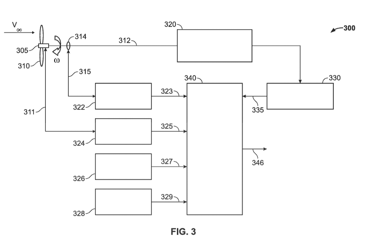
[0042] FIG. 3 is a block
diagram of a system 300 for determining airspeed
of an aircraft 100 in accordance with one exemplary implementation of the
disclosed embodiments.
[0043] The system 300
includes an air turbine 305/310/312, an air turbine
power converter and transducer(s) 320, a sensor 314, an angular speed
transducer
322, a blade angle transducer 324, a static pressure transducer 326, a static
air
temperature transducer 328, a shaft power determination module 330, and an
airspeed computation module 340.
[0044] The air turbine
includes a turbine 305 having a propeller 310. The
propeller 310 has at least two blades that define a propeller diameter (D).
The
turbine 305 is coupled to a shaft 312. As the aircraft moves through the air
during
flight, the propeller 310 rotates at an angular velocity, which causes the
shaft 312
to also rotate and drive an electrical or hydraulic generator (not illustrated
in FIG.
3).
[0045] The sensor 314 is
coupled to the shaft 312, and configured to
measure an angular position of the shaft 312, or an angular speed at which the
shaft 312 rotates, which depending on the implementation, can be in units of
radians or degrees per unit time, or in units of revolutions per unit time. In
the
non-limiting description that follows, the sensor 314 generates a shaft
angular
velocity signal 315 in response to the rotation of the shaft 312; however, it
is
- 10 -
CA 02863168 2014-07-29
WO 2013/116448 PCT/US2013/024028
noted that in other implementations, the sensor 314 can also include the
functionality of the angular speed transducer 322 such that the angular speed
transducer 322 can be eliminated, and such that the sensor 314 outputs an
angular
velocity signal (o)) in radians or degree per unit time. Further, in some
implementations, the sensor 314 can output an angular velocity signal (n) that
is
in revolutions per unit time, in which block 632 of FIG. 6 can also be
eliminated.
For instance, in some embodiments, the sensor 314 measures an angular velocity
of the shaft in revolutions per unit time such as revolutions per minute or
revolutions per second, and outputs a signal that can be directly used by the
airspeed computation module 340 without further processing.
[0046] The air turbine power converter and transducer(s) 320 are generally
shown in a block since the type of power converter and additional
transducer(s)
can vary depending on the implementation. For example, in one implementation,
the power converter can be an electrical power generator and controls, and the
additional transducers can include current, voltage and/or power sensors. In
another implementation, the power converter can be a hydraulic power
generator,
and the additional transducers can include hydraulic pressure and flow
transducers.
[0047] In this particular implementation, the angular speed transducer 322
is
coupled to the sensor 314, and configured to receive signal 315. As the
propeller
310 rotates, the angular speed transducer 322 generates a shaft angular
velocity
output signal 323 in response to signal 315. The shaft angular velocity output
signal 323 can be in units of radians/degrees per unit time, or revolutions
per unit
time. In the later case, this allows block 632 of FIG. 6 to be eliminated.
[0048] The blade angle transducer 324 is coupled to the propeller 310. The
blade angle transducer 324 is configured to measure a blade incidence or pitch
angle 311 as the propeller 310 rotates, and to generate a blade angle output
signal
325 in response to the measured blade incidence or pitch angle 311. For sake
of
clarity, the blade incidence angle is the angle of incidence of the mean
aerodynamic chord of a blade, and is related to the pitch of a blade or
propeller.
-11-
CA 02863168 2014-07-29
WO 2013/116448
PCT/US2013/024028
As will be described below, this blade angle measurement is utilized in the
blade
pitch angle computation module 625.
[0049] The
static pressure transducer 326 is configured to sense static
pressure and to generate a static air pressure output signal 327 in response
to the
static pressure that is sensed. The static air temperature transducer 328 is
configured to sense static air temperature and to generate a static air
temperature
output signal 329 in response to the static air temperature that is sensed.
[0050] The shaft
power determination module 330 includes measurement
hardware and computation software that can be used to generate a shaft output
power signal 335. The shaft output power signal 335 provides an indication of
turbine power, and can be used along with other measured or sensed parameters
and turbine configuration inputs (e.g., turbine shaft rotational speed,
propeller
diameter and blade angle) to generate a computed airspeed. The computed shaft
power (Ps) output signal 335 can be directly measured or computationally
determined. Shaft power (Ps) can be expressed in Watts. Various
implementations of the shaft power determination module 330 that can be used
together or separately depending on the implementation will be described below
with reference to FIGS. 4-6.
[0051] The
airspeed computation module 340 generates an airspeed output
signal 346 based on the shaft output power signal 335 and other inputs that
include one or more of the shaft angular velocity output signal 323, the blade
angle output signal 325, the static air pressure output signal 327, the static
air
temperature output signal 329. Depending on the implementation, the airspeed
computation module 340 can be implemented using a relational algorithm or
database between total power 355 and free-stream airspeed (Vc) 346, which can
be analytically and/or empirically determined based on the known concepts of
classical propeller and blade-element momentum theory. One exemplary
implementation of the airspeed computation module 340 will be described below
with reference to FIG. 7.
- 12 -
CA 02863168 2014-07-29
WO 2013/116448 PCT/US2013/024028
[0052] FIG. 4 is a block
diagram of a power converter and transducer portion
320-1 of an electrical air turbine system and a shaft power determination
module
330-1 that can be implemented in the system 300 of FIG. 3 in accordance with
one exemplary implementation of the disclosed embodiments.
[0053] In this embodiment,
air turbine system is an electrical air turbine
system air turbine power converter and transducer(s) 320-1 are implemented via
an air turbine electrical generator 331 and an electrical generator control
module
332 that can include additional transducers including current, voltage and/or
power sensors. As will be described below, measured electrical power
generation
can be used to infer input shaft power provided from the turbine.
[0054] The air turbine
electrical generator 331 is coupled to the shaft 312, and
to the electrical generator control module 332. The shaft 312 rotates at an
angular
velocity (o)) as the propeller 310 rotates, which causes the air turbine
electrical
generator 331 to generate an electrical load output signal in response to
rotation of
the shaft 312.
[0055] Once the blade angle
and rotational speed of the air turbine becomes
sufficiently stabilized, the electrical generator control module 332 is
configured to
directly and continuously measure the electrical load output signal of the
generator, to calculate measured electrical load, and to generate a measured
electrical load in response to electrical load output signal. Alternatively,
the
generator load output can be measured by the aircraft emergency electrical bus
(EBUS).
[0056] The shaft power
determination module 330-1 includes an electrical
power computation module 333 and a shaft power determination sub-module 334
[0057] The electrical power
computation module 333 is coupled to the
electrical generator control module 332. The electrical power computation
module 333 is configured to generate an electrical power output signal based
on
the measured electrical load. For example, in one embodiment, the measured
electrical load is current, and the electrical power computation module 333 is
configured to continuously compute instantaneous electrical power (PE)
(typically
- 13 -
CA 02863168 2014-07-29
WO 2013/116448 PCT/US2013/024028
expressed in Watts) to generate an electrical power output signal. In one
implementation, this is done by computing the product of the measured current
and voltage provided from the electrical generator control module 332.
[0058] The shaft power determination sub-module 334 is coupled to the
electrical power computation module 333. The shaft power determination module
334 is configured to generate the shaft output power signal 335 based on the
electrical power output signal from the electrical power computation module
333.
For example, in one embodiment, the generalized turbine power input to the
generator 331 can be determined from the relationship: PS=PEtrim-e, where Ps
is
the instantaneous mechanical turbine shaft power input to the generator 331,
PE is
the electrical power load from the generator and rim_e is a mechanical-to-
electrical
power transfer efficiency factor. The instantaneous mechanical turbine shaft
power (Ps) input to the generator 331 is directly related to the shaft power
being
generated by the turbine's propeller.
[0059] FIG. 5 is a block diagram of a power converter and transducer
portion
320-2 of a hydraulic air turbine system and a shaft power determination module
330-2 that can be implemented in the system 300 of FIG. 3 in accordance with
another exemplary implementation of the disclosed embodiments.
[0060] In this embodiment, air turbine system is hydraulic air turbine
system
and the air turbine power converter and transducer(s) 320-1 are implemented
via
an air turbine hydraulic pump 431 that is coupled to the propeller 310 via a
shaft
312, a hydraulic pressure transducer 432-1 and a hydraulic flow transducer 432-
2
coupled to the air turbine hydraulic pump 431. The shaft 312 rotates at an
angular
velocity (o)) as the propeller 310 rotates, which causes the air turbine
hydraulic
pump 431 to generate an air turbine hydraulic pump output in response to the
rotation of the shaft 312. As will be described below, measured hydraulic
power
generation can be used to infer input shaft power provided from the turbine.
[0061] Once the blade angle and rotational speed of the hydraulic air
turbine
becomes sufficiently stabilized, air turbine pump output pressure and flow are
measured. In one embodiment, the hydraulic pressure transducer 432-1 is
- 14 -
CA 02863168 2014-07-29
WO 2013/116448 PCT/US2013/024028
configured to receive the air turbine hydraulic pump output and to generate a
measured pressure output signal (p) in response to the air turbine hydraulic
pump
output. The hydraulic flow transducer 432-2 is configured to receive the air
turbine hydraulic pump output and to generate a measured flow output signal
(Q)
in response to the air turbine hydraulic pump output.
[0062] The shaft power determination module 330-2 includes a hydraulic
power computation module 433 and a shaft power determination sub-module 434.
[0063] The hydraulic power computation module 433 is coupled to the
hydraulic pressure transducer 432-1 and the hydraulic flow transducer 432-2,
and
is configured to generate a hydraulic power load (PH) output signal based on
the
measured pressure output signal (p) and the measured flow output signal (Q).
In
one embodiment, the hydraulic power computation module 433 determines the
product of the measured pressure output signal and flow output signals to
compute the hydraulic power load (PH) output signal as follows:
PH=P*Q,
where p is the hydraulic output pressure (typically in force per unit area,
e.g., psi)
and Q is the hydraulic flow from the hydraulic air turbine (typically measured
in
unit volume per unit time, e.g., in3/sec).
[0064] The shaft power determination sub-module 434 is coupled to the
hydraulic power (PH) computation module 433, and is configured to continuously
generate the shaft output power signal 335 (that reflects instantaneous power)
based on the hydraulic power load (PH) output signal. For instance, in one
embodiment, given the hydraulic power load (PH) from the hydraulic pump, the
generalized turbine power input to the pump can be determined from the
relationship:
Ps=P11/11m-h,
where Ps is the instantaneous mechanical turbine shaft power input to the
pump,
which is directly related to the shaft power being generated by the propeller
turbine, PH is the hydraulic power, and rim_h is the mechanical-to-hydraulic
power
transfer efficiency factor.
- 15 -
CA 02863168 2014-07-29
WO 2013/116448 PCT/US2013/024028
[0065] FIG. 6 is a block
diagram of a power converter and transducer
portion 320-3 of a generic air turbine system and a shaft power determination
module 330-3 that can be implemented in the system 300 of FIG. 3 in accordance
with one exemplary implementation of the disclosed embodiments.
[0066] In this embodiment,
air turbine system can include any known air
turbine (e.g., an electrical air turbine, a hydraulic air turbine, etc.). The
power
converter and transducer portion 320-3 is illustrated in FIG. 6 as a generic
air
turbine power sink 532 that is coupled to an air turbine via a shaft 312
(representative of a power generator that generates power as the shaft 312
rotates), and a torque transducer 531 coupled to the shaft 312. The torque
transducer 531 can be implemented using strain-based instrumentation such as a
strain gauge or other such device.
[0067] As the propeller 310
(FIG. 3) rotates, the shaft 312 rotates at an
angular velocity (o)). The torque transducer 531 directly measures torque
generated by the shaft 312, and outputs a shaft torque output signal that
reflects
the instantaneous torque generated by the shaft 312 as it rotates. The
instantaneous torque generated by the shaft 312 is directly related to the
power
being generated by the propeller. Turbine shaft torque can be directly
measured
and used along with the shaft rotational velocity to infer input shaft power
provided from the turbine.
[0068] The shaft power
determination module 330-3 includes a shaft power
determination sub-module 534 that is coupled to the torque transducer 531 and
to
the angular speed transducer 322 of FIG. 3. The power (Ps) generated is equal
to
the product of torque (T) and shaft rotational velocity (o)) in radians per
unit time
(e.g., rad/sec). The shaft power determination sub-module 534 can generate a
computed shaft power (Ps) output signal 335 based on the product of the shaft
angular velocity (o)) output signal 323 and the shaft torque (T) output signal
as
follows:
Ps=T*co.
- 16-
CA 02863168 2014-07-29
WO 2013/116448 PCT/US2013/024028
[0070] Rotational speed (n)
in per unit time (e.g., revolutions per second or
revolutions per minute) is related to the rotational velocity (co) in radians
per unit
time by the relationship:
n=(27c*co).
[0071] FIG. 7 is a flow
diagram that shows some of the processing steps in
accordance with one exemplary implementation of an airspeed calculation method
that can be executed by the airspeed computation module 340 of FIG. 3 in
accordance with an exemplary implementation of the disclosed embodiments. In
one embodiment, the airspeed computation module 340 includes a blade pitch
angle computation module 625, an air density computation module 630, a
rotational speed computation module 632, a power coefficient generation module
636, a propeller advance ratio coefficient generation module 640, and an air
velocity computation module 644.
[0072] The blade pitch angle
computation module 625 computes a particular
value of a measured blade pitch angle (a,) based on a particular value of the
blade
angle output signal 325 from the blade angle transducer 324.
[0073] The air density
computation module 630 computes a particular free-
stream air density value 631 based on a particular value of the static air
pressure
output signal 327 and a particular value of the static air temperature output
signal
329.
[0074] The rotational speed
computation module 632 is optional and is
employed in implementations where the output signal 323 is not in revolutions
per
unit time (e.g., when the output signal 323 is in units of radians per second
or
degrees per second, etc.) In such implementations, the rotational speed
computation module 632 is configured to compute a particular value of a
rotational speed 633 based on a particular value of the output signal 323. For
example, in one implementation, the rotational speed computation module 632
computes the rotational speed (n) 633 per unit time (e.g., revolutions per
second
or revolutions per minute) based on the rotational velocity output signal (co)
323
in radians per unit time as follows:
- 17 -
CA 02863168 2014-07-29
WO 2013/116448 PCT/US2013/024028
n=(27c* co).
Cp=Ps/(pn3D5).
Cp(ai).
- 18-
CA 02863168 2014-07-29
WO 2013/116448 PCT/US2013/024028
exemplary graphs that illustrate the power coefficient (Cp) as a function of
advance ratio (J) for blade pitch angles of 15 , 20 and 25 . Other blade
pitch
angles could be considered or utilized, based on the operational envelope
needed.
[0079] The air velocity
computation module 644 configured to generate a
particular instantaneous value of the airspeed output signal (-Vc) 346 based
on the
particular instantaneous value of the shaft rotational speed (n) 633 (in
revolutions
per unit time), the propeller diameter (D) (in length units), and the
particular
instantaneous value of a propeller advance ratio coefficient (J) 642. The
propeller
advance ratio coefficient (J) 642 is a non-dimensional coefficient that
relates
forward free-stream velocity with the product of the propeller's rotational
speed
and diameter as follows:
J=VGI(n*D)
[0081] In one embodiment,
given the non-dimensional advance ratio
coefficient (J) 642, then free-stream velocity (-Vs) 346 can be computed using
the
equation:
VG0=n*D*J.
where n is the shaft rotational speed (in revolutions per unit time), D is the
propeller diameter (in length units) and J is the advance ratio coefficient.
The
free-stream air velocity (Voo) is typically expressed in speed per unit time,
e.g.,
Knots-Calibrated Air Speed (KCAS) or Knots-True Air Speed (KTAS).
[0082] Thus, the disclosed
embodiments can utilize the inherent features of
an air turbine along with additional sensors to allow for calculation of free
stream
airspeed. This airspeed data can then be passed to the aircraft flight crew
display
for presentation.
[0083] One of the benefits
of the disclosed embodiments is that they can be
used to acquire airspeed when pitot-static measurement devices are
unavailable.
In one implementation, the systems and methods in accordance with the
disclosed embodiments can be employed in an aircraft as a secondary or backup
airspeed measurement source for use in emergency situations when primary pitot-
static airspeed measurement systems experience a partial or complete failure.
For
- 19 -
CA 02863168 2014-07-29
WO 2013/116448 PCT/US2013/024028
example, in the event pitot sensors fail due to blockage or other reasons, the
air
turbine could be deployed to restore the airspeed data. The use of air turbine
systems for determining airspeed is not subject to many of the same failure
modes
that the primary pitot-static airspeed measurement systems are subject to
(e.g. ,a
blocked pitot port or pitot heater failure) since they do not rely on data
from pitot-
static probes.
[0084] Those of skill in the
art would further appreciate that the various
illustrative logical blocks/tasks/steps, modules, circuits, and algorithm
steps
described in connection with the embodiments disclosed herein may be
implemented as electronic hardware, computer software, or combinations of
both.
Some of the embodiments and implementations are described above in terms of
functional and/or logical block components (or modules) and various processing
steps. However, it should be
appreciated that such block components (or
modules) may be realized by any number of hardware, software, and/or firmware
components configured to perform the specified functions. To clearly
illustrate
this interchangeability of hardware and software, various illustrative
components,
blocks, modules, circuits, and steps have been described above generally in
terms
of their functionality. Whether such functionality is implemented as hardware
or
software depends upon the particular application and design constraints
imposed
on the overall system. Skilled artisans may implement the described
functionality
in varying ways for each particular application, but such implementation
decisions should not be interpreted as causing a departure from the scope of
the
present invention. For example, an embodiment of a system or a component may
employ various integrated circuit components, e.g., memory elements, digital
signal processing elements, logic elements, look-up tables, or the like, which
may
carry out a variety of functions under the control of one or more
microprocessors
or other control devices. In addition, those skilled in the art will
appreciate that
embodiments described herein are merely exemplary implementations
[0085] The various
illustrative logical blocks, modules, and circuits
described in connection with the embodiments disclosed herein may be
- 20 -
CA 02863168 2014-07-29
WO 2013/116448 PCT/US2013/024028
implemented or performed with a general purpose processor, a digital signal
processor (DSP), an application specific integrated circuit (ASIC), a field
programmable gate array (FPGA) or other programmable logic device, discrete
gate or transistor logic, discrete hardware components, or any combination
thereof
designed to perform the functions described herein. A general-purpose
processor
may be a microprocessor, but in the alternative, the processor may be any
conventional processor, controller, microcontroller, or state machine. A
processor
may also be implemented as a combination of computing devices, e.g., a
combination of a DSP and a microprocessor, a plurality of microprocessors, one
or more microprocessors in conjunction with a DSP core, or any other such
configuration. The word "exemplary" is used exclusively herein to mean
"serving
as an example, instance, or illustration." Any embodiment described herein as
"exemplary" is not necessarily to be construed as preferred or advantageous
over
other embodiments.
[0086] The steps of a method or algorithm described in connection with the
embodiments disclosed herein may be embodied directly in hardware, in a
software module executed by a processor, or in a combination of the two. A
software module may reside in RAM memory, flash memory, ROM memory,
EPROM memory, EEPROM memory, registers, hard disk, a removable disk, a
CD-ROM, or any other form of storage medium known in the art. An exemplary
storage medium is coupled to the processor such the processor can read
information from, and write information to, the storage medium. In the
alternative, the storage medium may be integral to the processor. The
processor
and the storage medium may reside in an ASIC.
[0087] In this document, relational terms such as first and second, and the
like may be used solely to distinguish one entity or action from another
entity or
action without necessarily requiring or implying any actual such relationship
or
order between such entities or actions. Numerical ordinals such as "first,"
"second," "third," etc. simply denote different singles of a plurality and do
not
imply any order or sequence unless specifically defined by the claim language.
-21-
CA 02863168 2014-07-29
WO 2013/116448 PCT/US2013/024028
The sequence of the text in any of the claims does not imply that process
steps
must be performed in a temporal or logical order according to such sequence
unless it is specifically defined by the language of the claim. The process
steps
may be interchanged in any order without departing from the scope of the
invention as long as such an interchange does not contradict the claim
language
and is not logically nonsensical.
[0088] Furthermore, depending on the context, words such as "connect" or
"coupled to" used in describing a relationship between different elements do
not
imply that a direct physical connection must be made between these elements.
For example, two elements may be connected to each other physically,
electronically, logically, or in any other manner, through one or more
additional
elements.
[0089] While at least one exemplary embodiment has been presented in the
foregoing detailed description, it should be appreciated that a vast number of
variations exist. It should also be appreciated that the exemplary embodiment
or
exemplary embodiments are only examples, and are not intended to limit the
scope, applicability, or configuration of the invention in any way. Rather,
the
foregoing detailed description will provide those skilled in the art with a
convenient road map for implementing the exemplary embodiment or exemplary
embodiments. It should be understood that various changes can be made in the
function and arrangement of elements without departing from the scope of the
invention as set forth in the appended claims and the legal equivalents
thereof
- 22 -