Note: Descriptions are shown in the official language in which they were submitted.
CA 02863290 2014-07-30
WO 2013/113815 PCT/EP2013/051898
1
A System and Method for Manufacturing a Wind Turbine Blade
Field of the Invention
The present invention relates to a system and method of manufacture of a wind
turbine
blade using a post-moulding station.
Background of the Invention
Wind turbine blades are normally manufactured as first and second blade
shells, using a
pair of adjacent blade moulds. The blade moulds comprise first and second
moulding
surfaces conforming to the upwind and downwind halves (or the suction and
pressure
sides) of a wind turbine blade, the first blade mould used to form a first
blade shell and the
second blade mould used to form a second blade shell, the shells subsequently
joined
together to form a wind turbine blade.
A fibrous composite material is initially layered on top of the first and
second moulding
surfaces, the layers of material conforming to the contours of the moulds to
form the
external aerodynamic surfaces of the blade shells. Once sufficient layers of
the fibrous
material have been applied in the moulds, a resin is applied to the fibrous
material to cure
the material, to allow it to harden. The resin is most commonly infused using
a vacuum
bag system, and takes approximately 2-3 hours from the start of resin infusion
to a time
when the blade shells are effectively cured to have a resilient structure.
Once the blade shells have sufficiently cured, the vacuum bags are removed and
further
operations can be performed on the hardened shells. For example, blade
laminates
and/or webs can be installed in the blade shells, various repair or patching
operations may
be carried out on the shells, grinding of shell surfaces, etc.
Next, an adhesive glue is applied to the edges of the shells while in the
moulds. The blade
moulds are linked via a hinged turning mechanism, and a first of the blade
moulds,
containing a first of the blade shells, is accordingly turned relative to the
second mould
and shell, such that the first shell is positioned above the second shell.
This allows for the
blade shells to be closed together along the edge of the shells, to form a
complete wind
turbine blade having an upwind and a downwind side. To allow for secure
bonding of the
shells together, a suitable pressure is maintained along the exterior surfaces
of the blade
shells by the blade moulds, usually for approximately 3-4 hours.
CA 02863290 2014-07-30
WO 2013/113815 PCT/EP2013/051898
2
Once the complete wind turbine blade is fully adhered, the first blade mould
may be
hinged back to an open state, allowing access to the contained wind turbine
blade. The
blade can then be de-moulded from the second blade mould, and supported using
blade
carts to perform additional production operations, e.g. grinding of the
external blade
surface, coating, etc.
High-quality blade moulds are one of the most expensive pieces of equipment in
the blade
manufacturing process, requiring extensive tooling and manufacture before use
to ensure
accurate reproduction of desired blade profiles, as well as to allow for the
turning of the
moulds to bond blade shell parts together. In addition, even a minor
difference in blade
characteristics such as length, camber, etc. will in general require a
completely new blade
mould for the manufacturing process.
Blade moulds in use in current processes can cost approximately Ã1-3 million
to
manufacture and, dependent on where the moulds are made, extensive
transportation
time may be a factor before a new mould can be used at a manufacturing plant.
This
introduces considerable expense and lead time in the implementation of a
manufacturing
process for a new wind turbine blade.
Accordingly, one of the limitations to efficient implementation of wind
turbine technology is
the time required for the initial setup of a blade manufacturing system. A
further limitation
is the time taken for the manufacturing of individual blades within such a
system.
It is an object of the invention to provide a system and a method of
manufacture of a wind
turbine blade which reduces these limitations.
Summary of the Invention
Accordingly, there is provided a method of manufacturing a wind turbine blade
of at least
40 metres in length, the method comprising the steps of:
curing at least a section of a first wind turbine blade shell in a first blade
mould;
curing at least a section of a second wind turbine blade shell in a second
blade
mould;
transferring said first and second cured blade shells from said first and
second
blade moulds to a post-moulding station;
closing said first and second cured blade shells to form a closed wind turbine
blade shell, and
CA 02863290 2014-07-30
WO 2013/113815 PCT/EP2013/051898
3
bonding said first and second cured blade shells in said closed wind turbine
blade
shell to form a wind turbine blade.
Performing the closing operation away from the blade moulds allows for a
greater
utilisation efficiency of the relatively expensive blade moulds, thereby
providing for a
greater throughput of wind turbine blades manufactured according to the
method.
Preferably, said closing step comprises the step of turning said first cured
blade shell
relative to said second cured blade shell in said post-moulding station to
form a closed
wind turbine blade shell, and wherein said step of bonding is performed on
said closed
wind turbine blade shell to form a wind turbine blade.
Preferably, the method comprises the step of performing at least one post-
moulding
operation on at least one of said first and second cured blade shells at said
post-moulding
station.
Additionally or alternatively, there is provided a method of manufacturing a
wind turbine
blade of at least 40 metres in length, the method comprising the steps of:
curing a first wind turbine blade shell in a first blade mould;
curing a second wind turbine blade shell in a second blade mould;
transferring said first and second cured blade shells from said first and
second
blade moulds to a post-moulding station;
performing at least one post-moulding operation on at least one of said first
and
second cured blade shells at said post-moulding station; and
bonding said first cured blade shell with said second cured blade shell to
form a
wind turbine blade.
Providing a post-moulding station for use during the manufacturing process
allows for
operations to be performed on the blade shells after curing, away from the
blade moulds,
which allows for the blade moulds to be re-used relatively quickly. In one
aspect, said
bonding step is performed subsequent to said at least one post-moulding
operation ¨ this
means that operations which are normally performed within the blade moulds
(e.g. web
installation, glue application, etc.) can be performed at the post-moulding
station, freeing
up the blade moulds at an earlier stage of the manufacturing process.
CA 02863290 2014-07-30
WO 2013/113815 PCT/EP2013/051898
4
The term "cured blade shells" is used herein to refer to blade shells which
have been
substantially cured by the curing operation, preferably to a level where the
blade shells
can be handled without undergoing significant deformation of the shell
structure. The
duration of the curing operation performed will depend on the type of curing
resin used in
the manufacture of the blade shells, but may be of the order of 2-3 hours
using standard
resins. However, it will be understood that the blade shells may continue to
undergo a
curing process within the body of the blade shells for several hours after the
denoted
curing operation.
While the steps of the method may be performed on at least a section of a wind
turbine
blade shell which may be assembled with other shell sections to form a
complete wind
turbine blade shell, preferably the steps of the method are performed on a
section of a
wind turbine blade shell which corresponds to substantially an entire blade
shell. In a
preferred embodiment, the steps of the method are performed on a section of a
blade
shell corresponding to at least 50% of an entire wind turbine blade shell,
further preferably
at least 70%. In this case, the remainder of the entire wind turbine blade
shell may be
formed from separate dedicated blade sections, e.g. a dedicated blade root
section and/or
a dedicated blade tip section.
Preferably, said first wind turbine blade shell and said second wind turbine
blade shell
substantially form respective upwind and downwind blade shells. Where
reference is
made to at least a section of a wind turbine blade shell, in a preferred
aspect this will be
interpreted to mean a longitudinal section of an upwind or a downwind blade
shell.
Preferably, the upwind or a downwind blade shells extend between a leading
edge end
and a trailing edge end to be located at respective leading and trailing edges
of a finished
wind turbine blade.
The method of manufacture is used to manufacture a blade for a wind turbine in
a quick
and efficient manner, at a manufacturing location. In one embodiment, said
post-moulding
station is provided local to, preferably adjacent to the blade mould, to
provide for a
relatively short transfer distance between the blade mould and the post-
moulding station.
Further preferably, said bonding step is performed local to said post-moulding
station,
preferably using said post-moulding station.
CA 02863290 2014-07-30
WO 2013/113815 PCT/EP2013/051898
In an alternative embodiment, the cured blade shells may be transported from
the
moulding location to a remote assembly location, for finishing and assembly
using a post-
moulding station.
5 Preferably, said wind turbine blade shells are load-bearing wind turbine
blade shells.
It will be understood that said curing steps comprise curing said blade shells
to a level
wherein the shells may be handled and transferred from a blade mould to a
separate
post-moulding station without deformation. It will further be understood that
subsequent
curing of the blade shells may occur in the post-moulding station, or the
blade shells may
undergo a second curing operation after demoulding from the blade mould, e.g.
in a
dedicated curing oven.
In one aspect, there is provided a method of manufacturing a wind turbine
blade of at
least 40 metres in length, the blade comprising a profiled contour including a
pressure
side and a suction side, and a leading edge and a trailing edge with a chord
having a
chord length extending therebetween, the profiled contour, when being impacted
by an
incident airflow, generating a lift, the method comprising the steps of:
curing a first wind turbine blade shell in a first blade mould, said first
wind turbine
blade shell comprising a body substantially forming a pressure side of a wind
turbine
blade having a leading edge and a trailing edge;
curing a second wind turbine blade shell in a second blade mould, said second
wind turbine blade shell comprising a body substantially forming a suction
side of a wind
turbine blade having a leading edge and a trailing edge;
transferring at least one of said first and second cured blade shells,
preferably
both of said shells, from said first and second blade moulds to a post-
moulding station;
performing at least one post-moulding operation on at least one of said first
and
second cured blade shells at said post-moulding station; and
subsequently bonding said first cured blade shell with said second cured blade
shell to form a wind turbine blade.
Preferably, said at least one post-moulding operation is selected from one or
more of the
following: a blade shell repair operation, a blade shell grinding operation, a
blade root
flange coupling operation, a blade web installation operation, a gluing
operation, a coating
operation, an assembly operation to assemble at least two separate sections of
a wind
CA 02863290 2014-07-30
WO 2013/113815 PCT/EP2013/051898
6
turbine blade shell to form a single wind turbine blade shell, a main laminate
installation
operation, an overlamination operation, installation of blade sensor systems,
installation of
blade lightning protection systems, a geometry check operation, a geometry
adjustment
operation to push or pull portions of the blade shell into position, a
secondary curing
operation in for example an oven, additions of external components, e.g. aero
devices,
fans, spoilers, stall fences, or any other suitable manufacturing or assembly
operations, or
any suitable non-destructive testing activity, e.g. wrinkle measurements,
ultra sonic
thickness measurement, phased array testing of glue bonds, etc.
Preferably, the post-moulding station comprises at least one blade cradle to
receive a
cured blade shell, and wherein said step of transferring comprises
transferring said first
cured blade shell to a first blade cradle and transferring said second cured
blade shell to a
second blade cradle.
Preferably, the method comprises the step of providing at least one of said
first and
second blade cradles as a substantially open-frame structure.
Providing at least one of the cradles as an open-framed structure allows that
the at least
one post-moulding operation may be performed on substantially any surface of a
cured
blade shell contained in the cradle. This allows for workers to easily access
practically any
part of the shell, to easily and effectively carry out operations which
previously would be
delayed until after the blade moulding process had carried out and the
completed wind
turbine blade removed from the blade moulds, e.g. grinding operations,
coating, etc.
Furthermore, as the cradles are provided to handle a substantially cured
shell, there is a
reduced need for 100% geometry support of the entire shell. As a consequence,
the
cradle does not have to be a stiff and strong component to provide complete
support to
every part of the shell surface, and thus can be formed of less rigid, lighter
components
and be of a reduced height ¨ thereby reducing the height required during a
possible
turning operation of the cradle. The open-framed construction will be
understood to relate
to a structure which provides a non-continuous support surface to receive a
portion of a
shell for a wind turbine blade.
Additionally or alternatively, at least one of said first and second blade
cradles comprises
a plurality of support members to provide support to a surface of at least one
of said first
and second cured blade shells, and wherein the method comprises the step of
removing
at least one of said support members to provide access to a surface of at
least one of said
CA 02863290 2014-07-30
WO 2013/113815 PCT/EP2013/051898
7
first and second cured blade shells, to facilitate said step of performing a
post-moulding
operation.
The use of removable support members allows for increased access to surfaces
of the
shells. The support members may be removed to provide direct access to that
section of
the surface initially supported by the support member in question. After the
appropriate
post-moulding operations are performed, the support member may be replaced in
the
cradles in question. It will be understood that this step may also be
performed for any
intra-bonding operations. It will be understood that the term "plurality" may
refer to any
suitable arrangement of a support surface to receive and support a portion of
a blade
shell, and which preferably may be moveable relative to the blade cradle. For
example, a
flexible support surface coupled to an array of moveable actuators may be
provided, the
actuators operable to adjust the shape of the flexible surface to bring
sections of the
flexible support surface into and out of contact with a portion of a supported
blade shell, to
provide access to the surfaces of said blade shell.
Preferably, said step of transferring comprises demoulding said first and
second cured
blade shells from said first and second blade moulds.
Preferably, said step of transferring comprises applying a vacuum lifting
force to said first
and second cured blade shells to demould said first and second cured blade
shells
Preferably, at least one of said first and second blade cradles comprises at
least one
vacuum clamp, and wherein said step of transferring comprises applying a
vacuum
clamping force to a surface of at least one of said first and second cured
blade shells
received within said at least one blade cradle, to retain said at least one
blade shell within
said at least one blade cradle.
The use of moveable vacuum clamps to secure the blade shells provides for a
secure
coupling mechanism which can be selectively applied with minimum additional
worker
operations.
Preferably, said at least one vacuum clamp is initially provided in a
retracted position on
said at least one blade cradle, and wherein said step of transferring
comprises the step of
advancing said at least one vacuum clamp from said retracted position to bear
against a
CA 02863290 2014-07-30
WO 2013/113815 PCT/EP2013/051898
8
surface of said at least one blade shell to retain said at least one blade
shell within said at
least one blade cradle.
Preferably, the method comprises the step of retracting said vacuum clamp to
said
retracted position when it is desired to remove said at least one blade shell
from said at
least one blade cradle.
Preferably, said step of performing at least one post-moulding operation
comprises
applying an adhesive at a leading edge and a trailing edge of at least one of
said first and
second cured blade shells, and wherein said step of bonding comprises
arranging said
first and second cured blade shells to adhere the leading edge of the first
blade shell to
the leading edge of the second blade shell, and to adhere the trailing edge of
the first
blade shell to the trailing edge of the second blade shell.
It will be understood that the invention is not limited to a direct connection
between the
respective leading and trailing edges of the shells, e.g. a tail piece or
insert may be
positioned between the leading edges and/or trailing edges of the shells.
Preferably, said step of bonding comprises moving said first blade cradle
containing said
first cured blade shell relative to said second blade cradle containing said
second cured
blade shell, to close said first and second cured blade shells to form a wind
turbine blade.
Preferably, said first blade cradle is hingedly coupled to said second blade
cradle, and
wherein the step of moving comprises hinging said first blade cradle or said
second blade
cradle to close said first and second cured blade shells.
The cradles may be further used as turning devices. As an alternative, there
could be a
separate station used for turning operations, wherein the blade shells are
moved from the
post-moulding station to the turning station after post-moulding operations
are completed.
Preferably, the method further comprises the step of aligning said first cured
blade shell
with said second cured blade shell such that the leading edge and trailing
edge of said
first cured blade shell are in register with the respective leading edge and
trailing edge of
said second cured blade shell during said bonding step.
The cradles can be moved to adjust for over/under bites between the shells.
CA 02863290 2014-07-30
WO 2013/113815 PCT/EP2013/051898
9
Preferably, said step of aligning comprises translationally moving at least
one of said first
and second blade cradles, preferably, relative to the other of said first and
second blade
cradles, to align the first and second cured blade shells contained within
said first and
second blade cradles.
The cradles are preferably positioned such that initially the leading edge
side of said first
blade shell is provided adjacent the leading edge side of said second blade
shell. The
step of moving (preferably hinging) is performed such that the trailing edge
side of said
first blade shell is brought into contact with the trailing edge side of said
second blade
shell.
Preferably, said first and second cured blade shells have a profiled contour
dependent on
the wind turbine blade to be manufactured, wherein at least one of said first
and second
blade cradles comprises a plurality of variable support members to support a
surface of a
blade shell to be received in said blade cradle, and wherein the method
comprises the
step of:
prior to said step of transferring, adjusting the variable support members of
at
least one of said first and second blade cradles based on the profiled contour
of the blade
shell to be received in said blade cradle.
This step provides for the adjustment of the support ribs/arms to accommodate
the shell
member to be received. This allows for the re-use of the cradles for different
blade shell
types/dimensions etc.
Preferably, said step of adjusting comprises varying said support members to
present a
support surface substantially conforming to the profiled contour of the blade
shell to be
received in said blade cradle.
Preferably, the post-moulding station is at least partly provided as a modular
construction
of a plurality of interchangeable station sub-modules, said sub-modules
coupled together
to form said post-moulding station, wherein the method comprises the steps of:
selecting a plurality of sub-modules based on a set of characteristics of the
blade
being manufactured, and
assembling the selected plurality of sub-modules to form said post-moulding
station.
CA 02863290 2014-07-30
WO 2013/113815 PCT/EP2013/051898
By providing a modular post-moulding station, the particular construction of
station can be
varied to accommodate the particular blade being manufactured. The
characteristics of
the blade being manufactured may include any combination of, but are not
limited to:
5 blade length, blade chord, blade camber, blade aerodynamic profile, blade
shell thickness,
etc.
It will be understood that the sub-modules may comprise structures having
different
lengths, widths, etc. Some sub-modules may be designed to receive different
portions of a
10 wind turbine blade shell, for example a section for receiving a root
section of a blade shell
may comprise a flange section for securing to the root end of the shell. A
section for
receiving a tip end may have a reduced width compared to a section for
receiving a
portion of the blade from towards the mid-point of the blade along the length
of the blade
shell, i.e. a portion having a longer chord length than the tip end of the
shell.
Preferably, the method comprises the step of providing at least one of said
first blade
mould and said second blade mould as a substantially fixed mould. Preferably,
the mould
has substantially rigid foundations, e.g. concrete foundations.
Providing the blade moulds as fixed installations means that the moulds can be
relatively
easily produced, and mould costs can be kept relatively low.
Preferably, the method comprises the step of:
laying up a fibre-based material in an internal surface of a blade shell mould
to
form an uncured wind turbine blade shell.
The lay-up operation may be used for both of the first and second blade
moulds, to form
uncured first and second blade shells. The lay-up may be a manual or hand lay-
up
operation, or an automatic lay-up operation, e.g. spray lay-up, tape lay-up,
fibre pultrusion,
automotive lay-up of plies, etc.
Preferably, said step of curing comprises infusing said uncured wind turbine
blade shell
with a resin to cure the wind turbine blade shell. This infusion step may be
an automatic or
a manual process.
CA 02863290 2014-07-30
WO 2013/113815 PCT/EP2013/051898
11
Preferably, the method further comprises, following said transferring step,
iteratively
repeating said steps of laying up and curing in said first and second blade
moulds, to
provide subsequent first and second cured blade shells.
By performing the next lay-up and curing operation using the moulds freed up
by the step
of transferring, the productivity rate of the moulds is greatly increased, as
a new moulding
operation can be performed as soon as the curing of the previous blade shells
is
completed. Accordingly, occupancy time of the blade moulds due to post-
moulding
operations is reduced, preferably eliminated, providing for a more efficient
use of overall
resources and equipment.
Preferably, the method further comprises iteratively repeating said step of
transferring, to
transfer said subsequent first and second cured blade shells to a post-
moulding station.
The cured shells may be transferred to a new post moulding station, or may be
transferred
to the post moulding station used for the first pair of blade shells.
Preferably, the method further comprises iteratively repeating the steps of
performing at
least one post-moulding operation on at least one of said subsequent first and
second
cured blade shells at said post-moulding station, and bonding said subsequent
first and
second cured blade shells to form a wind turbine blade.
The transferring of cured shells to the post moulding station for subsequent
post-moulding
operations allows for a streamlining of the blade production process, as the
effectiveness
of the individual manufacturing components, i.e. the blade moulds and the post
moulding
stations, is maximized. Such a system allows for the use of low-cost blade
moulds, which
may be easily manufactured and replaced if necessary.
Relating to the step of bonding, preferably, the method further comprises the
step of
performing at least one intra-bonding operation on at least one of said blade
shells in at
least one of said first and second blade cradles, during the step of bonding
said first cured
blade shell with said second cured blade shell to form a wind turbine blade.
Some operations may be performed while the adhesive between the shells is
setting.
Preferably this is accomplished through use of open-frame cradle structures.
CA 02863290 2014-07-30
WO 2013/113815 PCT/EP2013/051898
12
Preferably, said at least one intra-bonding operation is selected from one or
more of the
following: a blade shell repair operation, a surface grinding operation, a
coating operation,
a blade root flange finishing operation.
Relating to the steps of curing, preferably the method further comprises the
step of
performing at least one intra-curing operation on at least one of said blade
shells in at
least one of said moulds, during the step of curing said blade shell.
Some operations may be performed while the blade is curing in the mould, if
the shell
requires additional time to cure.
Preferably, said at least one intra-curing operation is selected from one or
more of the
following: a grinding operation, a blade shell repair operation.
Further relating to the step of bonding, preferably the method further
comprises the step
of performing at least one post-bonding operation on at least one of said
blade shells in at
least one of said moulds, subsequent to said bonding step.
Preferably, said at least one post-bonding operation is selected from one or
more of the
following: a leading edge grinding operation, wherein the leading edge surface
of the
bonded wind turbine blade is grinded to a smooth surface; a trailing edge
grinding
operation, wherein the trailing edge surface of the bonded wind turbine blade
is grinded to
a smooth surface; a blade repair operation, wherein a defect in the blade
surface may be
corrected, e.g. by applying a filler material; a coating operation, wherein at
least one layer
of gel coat or erosion resistant material or tape is applied to the external
surface of the
bonded wind turbine blade.
In another aspect of the invention, there is provided a method of
manufacturing a wind
turbine blade comprising the steps of:
curing a wind turbine blade shell in a mould
transferring the cured blade shell from the mould to a post-moulding station;
performing at least one post-moulding operation on the cured blade shell at
said
post-moulding station; and
subsequently bonding said cured blade shell with a second cured blade shell to
form a wind turbine blade.
CA 02863290 2014-07-30
WO 2013/113815 PCT/EP2013/051898
13
There is also provided a post-moulding station for performing at least one
post-moulding
operation on at least a section of a cured wind turbine blade shell of at
least 40 metres
length, the post-moulding station for use in the manufacture of a wind turbine
blade,
preferably in the method described above, and comprising:
at least one cradle to receive at least a section of a cured wind turbine
blade shell
transferred from a blade mould,
wherein at least one post-moulding operation can be performed on at least one
surface of said cured wind turbine blade shell received in said cradle.
By providing a cradle to receive a cured blade shell which is removed from a
blade mould,
this frees up the blade mould to be used for a subsequent lay-up and moulding
operation.
This increases the productivity of a single blade mould, and means that post-
moulding
operations can be performed outside of the mould. Preferably, the post-
moulding station
is operable to receive an entire blade shell, but it will be understood that
the post-
moulding station may receive a plurality of sections of a blade shell to be
assembled to
form a single blade shell, or alternatively, individual sections of a blade
shell may be
supported by individual post-moulding sections, for assembly into a single
blade shell.
Preferably, said post-moulding station comprises a first cradle to receive a
first cured
blade shell and a second cradle to receive a second cured blade shell, said
first and
second cured blade shells together substantially forming a wind turbine blade.
Providing two cradles at the post-moulding station allows for post-moulding
operations to
be performed at the same time on the shells forming a wind turbine blade.
Preferably, one
of the cradles is arranged to receive a pressure side shell of a wind turbine
blade, with the
other cradle arranged to receive a suction side shell of a wind turbine blade.
Preferably, the post-moulding station further comprises a closing mechanism
operable to
move said first cradle having a first cured blade shell relative to said
second cradle having
a second cured blade shell to form a closed cradle, such that said first cured
blade shell
may be joined to said second cured blade shell within said closed cradle to
form a wind
turbine blade.
Providing a closing mechanism at the post-moulding station means that the
closing
operation can be performed away from the blade moulds. This means that blade
moulds
of relatively simple construction can be used in the manufacturing process,
e.g. moulds
CA 02863290 2014-07-30
WO 2013/113815 PCT/EP2013/051898
14
which are fixed to a floor surface using a concrete foundation. It will be
understood that
either of the first or second cradles may be the hingedly moved cradle,
preferably said first
cradle.
Preferably, said first cradle is hingedly coupled to said second cradle,
wherein said closing
mechanism is operable to hinge said first cradle relative to said second
cradle.
Preferably, said first cradle is translationally moveable relative to said
second cradle when
said first and second cradles are closed, to align a first cured blade shell
with a second
cured blade shell within said closed cradle to form a wind turbine blade.
As the cradles can be moved relative to one another when in the closed
position, this
allows for the correction of any over- or under-bite misalignment between the
edges of the
cured blade shells contained in the cradles, e.g. as a result of manufacturing
variances
and/or post-moulding station alignment. It will be understood that either of
said first or
second cradles may be moveable relative to each other.
Preferably, said cured blade shells are received in said cradles with the
internal surfaces
of said shells facing upwards. Preferably, said post-moulding station is
configured such
that the first and second cradles are positioned adjacent each other.
Accordingly, a
hinging operation of one cradle with respect to the other provides an
effective method of
closing for the contained blade shells.
Preferably, said at least one post-moulding operation comprises applying an
adhesive to
at least one of said first and second cured blade shells, and wherein said
closing
mechanism is operable to move said first cradle relative to said second cradle
to bond
said first cured blade shell to said second cured blade shell to form a wind
turbine blade.
As the closing operation can be performed at the post-moulding station, the
cradles
provide the optimum location for the gluing operation to apply adhesive to one
or both of
the contained blade shells.
Preferably, said first and second cradles are arranged to apply a bonding
pressure to said
first and second cured blade shells when said first and second cradles are
closed.
CA 02863290 2014-07-30
WO 2013/113815 PCT/EP2013/051898
As the bonding of the shells may require the application of a bonding pressure
to the
shells to be bonded, the post-moulding station may be arranged to force the
shells
together to produce an effective bonding of the shells. Preferably, at least
one of said
cradles comprises a pressure member extending along substantially the length
of said
5 cradle. Preferably, said pressure member is operable to apply a pressure
along a portion
of the length of a cured blade shell received within said cradle. Preferably,
said pressure
member is operable to apply a bonding pressure along an edge of a cured blade
shell
received within said cradle.
10 Additionally or alternatively, said at least one post-moulding operation
is selected from
one or more of the following: a blade shell repair operation, a blade shell
grinding
operation, a blade web installation operation, a gluing operation, a coating
operation.
Preferably, said at least one cradle is a substantially open-framed structure
having a
15 plurality of support members to support a surface of a cured wind
turbine blade shell
received in said cradle.
The use of an open-framed structure as the cradle allows that post-moulding
operations
may be performed on substantially any surface of a cured blade shell contained
in the
cradle. This allows for workers to easily access practically any part of the
shell, to easily
and effectively carry out operations which previously would be delayed until
after the
blade moulding process had carried out and the completed wind turbine blade
removed
from the blade moulds, e.g. grinding operations, coating, etc.
Preferably, at least one of said plurality of support members is moveable
relative to a
cured blade shell received in said cradle, preferably removable, to provide
access to a
supported surface of a cured blade shell received in said cradle.
The support members may be adjusted, moved or removed to provide direct access
to
that section of the surface initially supported by the support member in
question. After the
appropriate post-moulding operations are performed, the support member may be
replaced or returned to position in the cradles in question.
Preferably, at least one of said plurality of support members is adjustable
such that the
geometry of a support surface presented by said plurality of support members
is variable
CA 02863290 2014-07-30
WO 2013/113815 PCT/EP2013/051898
16
to accommodate cured blade shells having different/diverse shell profiles.
As the support members can be adjusted, this allows for a configurable cradle
which can
support different types of cured blade shells. Accordingly, such a cradle can
be re-used in
manufacturing processes for differently shaped wind turbine blades.
Preferably, said plurality of support members comprise at least one vacuum
clamp device
operable to apply a vacuum against a portion of the surface of a cured blade
shell
received in said cradle, to secure said cured blade shell within said cradle.
Vacuum clamps provide a simple and controllable mechanism for securing a blade
shell
within a cradle. It will be understood that the clamps are operable to retain
a shell within
the cradle during possible movement of the cradle, e.g. hinging motion and/or
rotational
motion.
Preferably, said at least one vacuum clamp is movably mounted on said
plurality of
support members, said at least one vacuum clamp operable to move between a
first
retracted position wherein said at least one vacuum clamp is spaced from the
surface of a
cured blade shell received in said cradle, and a second advanced position
wherein said at
least on vacuum clamp abuts a surface of said cured blade shell received in
said cradle.
By moving the vacuum clamps between positions, it is possible to selectively
apply a
clamping force to a blade shell, while preventing damage to the clamps and/or
the blade
shell during positioning of the shell in the cradle, or subsequent removal.
Preferably, said at least one vacuum clamp is operable to engage with a
surface of a
blade shell received within said cradle, said vacuum clamp moveable to push
and/or pull a
portion of said surface of said blade shell to an adjusted position.
The securing of the vacuum clamps against the surfaces of the shells allows
for minor
adjustments to be made to the shell surfaces, e.g. to correct minor errors in
local
geometry.
Preferably, said cured wind turbine blade shell comprises a profiled shell
body having a
leading edge side and a trailing edge side, and wherein said post-moulding
station
comprises a first array of support members arranged to support a cured blade
shell at the
CA 02863290 2014-07-30
WO 2013/113815 PCT/EP2013/051898
17
leading edge side of the profiled shell body and a second array of support
members
arranged to support a cured blade shell at the trailing edge side of the
profiled shell body.
Providing support members or arms at the leading and trailing edges provides
for an
optimised and effective support of the cured blade shell within the cradle.
Furthermore,
such an arrangement of support members can aim in the application of a bonding
pressure to the edges of the blade shells when closing a pair of blade shells
to form a
wind turbine blade.
Preferably, said post-moulding station comprises a third array of support
members
arranged to support a cured blade shell at a point between the leading edge
side and the
trailing edge side of the profiled shell body.
Preferably, said third array of support members are arranged to support the
deepest
section of the profiled shell body between the leading edge side and the
trailing edge side
of the profiled shell body. Preferably, the third array of support members are
provided
along a line corresponding to the line of maximum thickness or camber of a
wind turbine
blade formed by said cured blade shell.
Preferably, said first and/or second arrays of support members are moveable to
allow
access to the leading and/or trailing edge sides of a profiled shell body
received within the
cradle.
By moving the first or second arrays, access is provided to the edges of the
shells and the
wind turbine blade, allowing for operations to be performed directly on these
edges, e.g. a
grinding operation. It will be understood that individual support members of
the first and
second arrays may be individually moveable, to provide access to a localized
section of
the leading and/or trailing edge sides of the contained shell body.
Preferably, said at least one cradle comprises a root flange clamping
mechanism, said
root flange clamping mechanism arranged to couple with a blade root flange of
a cured
blade shell to be received within said at least one cradle.
The cradle root flange clamping mechanism provides for a mounting point for a
blade shell
received within the cradle. As the blade root flange of the shell is
effectively designed to
support the weight of the blade shell body, it provides a useful initial
securing point for
CA 02863290 2014-07-30
WO 2013/113815 PCT/EP2013/051898
18
positioning the shell in the cradle. Furthermore, as the position of the root
flange is
defined in the cradle, it can be used to align a received blade shell with
respect to the
other support surfaces of the cradle.
Preferably, said at least one cradle is formed by a plurality of cradle sub-
modules.
A modular construction of cradle allows for the characteristics of the cradle
(which are
determined by the characteristics of the blade shell to be received in the
cradle) to be
varied through selection of appropriate sub-modules, e.g. cradle length, root
end width,
cradle width, etc.
Preferably, said plurality of sub-modules are selected based on the
characteristics of a
cured blade shell to be received within said at least one cradle.
Preferably, said plurality of sub-modules are selected from a range of sub-
modules having
alternative sub-module dimensions.
Preferably, said plurality of cradle sub-modules comprise a root end sub-
module arranged
to support a root end of a cured blade shell, a tip end sub-module arranged to
support a
tip end of a cured blade shell, and at least one intermediate sub-module
arranged to
support a portion of a cured blade shell between said root end and said tip
end.
It will be understood that the different types of sub-modules may have
different
characteristics, e.g. a tip end module may have a greater or lesser height to
accommodate
a tip end of a pre-bent blade (dependent on the direction of bending), a root
end module
may be provided with a connection for coupling to a root flange, etc.
Preferably, said post-moulding station further comprises at least one support
rail which
extends along at least a portion of the length of said post-moulding station
adjacent said
at least one cradle, said support rail operable to receive a tool for
performing a post-
moulding operation on a cured blade shell received in said at least one
cradle.
The use of a support rail allows for improved ease of mounting manufacturing
equipment
at the location of the blade shell to be worked upon. Providing a secure
mounting location
can improve the safety aspects of the process, as well as facilitating
automated
19
operations by presenting a configurable platform which can be used as a guide
for
movement of a tool with respect to an adjacent blade shell.
Preferably, said post-moulding station further comprises at least one tool,
wherein said tool
is moveable along said rail to perform a post-moulding operation along at
least a portion of
the length of a cured blade shell received in said cradle.
The tool may comprise a grinding device, a glue applicator device, a spray
coating device,
etc. The tool may be remotely controllable. In a further embodiment, said rail
is operable to
receive a tool to perform an intra-bonding or a post-bonding operation on a
wind turbine
blade formed by first and second blade shells.
in a further embodiment, at least one cradle is rotatable about a central
longitudinal axis of
said cradle.
By providing a rotatable cradle, access to different sections of a contained
blade shell may
be improved by rotating the cradle and contained shell.
Additionally or alternatively, said post moulding station comprises a first
cradle to receive a
first cured blade shell and a second cradle to receive a second cured blade
shell, said first
and second cradles operable to close to form a wind turbine blade from said
first and
second shells, wherein said first and second cradles are rotatable when closed
about a
central longitudinal axis of said closed first and second cradles.
75 A single cradle may be rotatable about its own longitudinal axis.
Additionally or
alternatively, the entire post-moulding station and/or the first and second
cradles may be
rotatable about a longitudinal axis when the cradles are closed, to allow for
rotation of the
wind turbine blade formed from first and second blade shells as the shells are
being
bonded together in the closecl'cradles.
In another aspect, there is provided a method of manufacturing a wind turbine
blade of at
least 40 metres in length, the method comprising the steps of: curing at least
a section of a
first wind turbine blade shell in a first blade mould; curing at least a
section of a second
wind turbine blade shell In a second blade mould; transferring said first and
second cured
blade shells from said first and second blade moulds to a post-moulding
station comprising
at least one blade cradle to receive a cured blade shell, wherein said step of
transferring
comprises transferring said first cured blade shell to a first blade cradle
and transferring
CA 2863290 2020-01-03
20
said second cured blade shell to a second blade cradle; closing said first and
second cured
blade shells to form a closed wind turbine blade shell, and bonding said first
and second
cured blade shells in said closed wind turbine blade shell to form a wind
turbine blade,
wherein the method further comprises the step of turning said first cured
blade shell relative
to said second cured blade shell in said post-moulding station to forrn the
closed wind
turbine blade shell, and wherein said step of bonding is performed on said
closed wind
turbine blade shell to form the wind turbine blade.
In still another aspect there is provided a manufacturing system for the
manufacture of wind
turbine blades formed from a pair of cured blade shells bonded together, the
system
comprising: a first upwind blade mould to produce at least a portion of a
first upwind cured
blade shell; a second downwind blade mould to produce at least a portion of a
second
downwind cured blade shell; a post-moulding station to receive said first and
second cured
blade shells from said first and second blade moulds, said post-moulding
station
comprising a first blade cradle to receive a first cured blade shell and a
second blade
cradle to receive a second cured blade shell, wherein a post-moulding
operation can be
performed on said first and second cured blade shells at said post-moulding
station; and a
closing mechanism operable to close said first and second cured blade shells
by turning
the first blade cradle relative to the second blade cradle to form a wind
turbine blade.
The use of such a manufacturing system provides for a relatively quick and
efficient
manufacture of wind turbine blade, allowing for maximum effective blade mould
usage. The
closing mechanism is operable to bond said first and second blade shells
together, to form
a wind turbine blade having an upwind and a downwind section. In one
embodiment, said
post-moulding station is local to said first and second blade moulds.
Alternatively, said
post-moulding station is remote from said first and second blade moulds.
In a preferred aspect of the invention, an entire blade shell is moulded using
a single blade
mould. In an alternative aspect, the blade shells may be moulded as individual
sections
with each section manufactured in a separate blade mould for later assembly.
Preferably, said post-moulding station comprises said closing mechanism.
Preferably, said post-moulding station comprises first and second blade
cradles operable to
receive said first and second cured blade shells.
CA 2863290 2020-01-03
20a
Preferably, the system further comprises a lifting device operable to demould
or remove
said first and second cured blade shells from said first and second blade
moulds.
Preferably, said lifting device is further operable to transfer said first and
second cured
blade shells to said post-moulding station.
Preferably, said first and second blade moulds are used in a lay-up process of
a fibrous
composite material to produce said first and second cured blade shells.
Preferably, said
manufacturing system further comprises an infusion mechanism operable to
infuse said
fibrous composite material with a resin to cure said fibrous composite
material to form said
CA 2863290 2020-01-03
CA 02863290 2014-07-30
WO 2013/113815 PCT/EP2013/051898
21
first and second cured blade shells, Said support modules may comprise
individual
supports for separate root sections, tip sections, and/or aerodynamic sections
of individual
blade shells.
Preferably, said post-moulding station comprises a post-moulding station as
described
above.
There is further provided a wind turbine blade manufactured using the system
and method
described above.
Description of the Invention
An embodiment of the invention will now be described, by way of example only,
with
reference to the accompanying drawings, in which:
Fig. 1 shows a wind turbine;
Fig. 2 shows a schematic view of a wind turbine blade;
Fig. 3 shows a schematic view of an airfoil profile of the blade of Fig. 2;
Fig. 4 illustrates an embodiment of a manufacturing process for a wind turbine
blade according to the invention;
Fig. 5 is a top plan view of an embodiment of a post-moulding station for use
in
the manufacture of a wind turbine blade according to the invention;
Fig. 6 is a perspective view of the post-moulding station of Fig. 5;
Fig. 7(a) is a side view of the post-moulding station of Fig. 5 when in an
open
state;
Fig. 7(b) is a side view of the post-moulding station of Fig. 5 when in a
closed
state;
Fig. 8(a) is an end view of the post-moulding station of Fig. 5 when in an
open
state;
Fig. 8(b) is an end view of the post-moulding station of Fig. 5 when in a
closed
state;
Fig. 9 is an enlarged perspective view of the root end of the post-moulding
station
of Fig. 5;
Fig. 10(a) is a front perspective view of a side support element of the post-
moulding station of Fig. 5;
Fig. 10(b) is a rear perspective view of a side support element of the post-
moulding station of Fig. 5;
CA 02863290 2014-07-30
WO 2013/113815 PCT/EP2013/051898
22
Fig. 11(a) is an enlarged perspective view of a side support element of Fig.
10
when the vacuum clamp members are retracted;
Fig. 11(b) is an enlarged perspective view of a side support element of Fig.
10
when the vacuum clamp members are advanced;
Fig. 12 is a perspective view of the open post-moulding station of Fig. 5 when
supporting a pair of cured blade shells;
Fig. 13 is a perspective view of the post-moulding station of Fig. 12 when
closed;
Fig. 14 is an enlarged perspective view of the root end of the post-moulding
station of Fig. 12;
Fig. 15(a) is a perspective view of a cradle body of a first cradle of the
post-
moulding station of Fig. 5;
Fig. 15(b) is a perspective view of the cradle body of Fig. 15(a) when
disassembled into separate modular sections; and
Fig. 16 is an overview of the manufacturing process according to the
invention.
Fig. 1 illustrates a conventional modern upwind wind turbine according to the
so-called
"Danish concept" with a tower 4, a nacelle 6 and a rotor with a substantially
horizontal
rotor shaft. The rotor includes a hub 8 and three blades 10 extending radially
from the hub
8, each having a blade root 16 nearest the hub and a blade tip 14 furthest
from the hub 8.
The rotor has a radius denoted R. While a three-bladed upwind wind turbine
design is
presented here, it will be understood that the invention may equally apply to
blades of
other wind turbine designs, e.g. two-bladed, downwind, etc.
Fig. 2 shows a schematic view of a first embodiment of a wind turbine blade 10
according
to an embodiment of the invention. The wind turbine blade 10 has the shape of
a
conventional wind turbine blade and comprises a root region 30 closest to the
hub, a
profiled or an airfoil region 34 furthest away from the hub and a transition
region 32
between the root region 30 and the airfoil region 34. The blade 10 comprises a
leading
edge 18 facing the direction of rotation of the blade 10, when the blade is
mounted on the
hub, and a trailing edge 20 facing the opposite direction of the leading edge
18.
The airfoil region 34 (also called the profiled region) has an ideal or almost
ideal blade
shape with respect to generating lift, whereas the root region 30 due to
structural
considerations has a substantially circular or elliptical cross-section, which
for instance
makes it easier and safer to mount the blade 10 to the hub. The diameter (or
the chord) of
the root region 30 is typically constant along the entire root area 30. The
transition region
CA 02863290 2014-07-30
WO 2013/113815 PCT/EP2013/051898
23
32 has a transitional profile 42 gradually changing from the circular or
elliptical shape 40
of the root region 30 to the airfoil profile 50 of the airfoil region 34. The
chord length of the
transition region 32 typically increases substantially linearly with
increasing distance r from
the hub.
The airfoil region 34 has an airfoil profile 50 with a chord extending between
the leading
edge 18 and the trailing edge 20 of the blade 10. The width of the chord
decreases with
increasing distance r from the hub.
It should be noted that the chords of different sections of the blade normally
do not lie in a
common plane, since the blade may be twisted and/or curved (i.e. pre-bent),
thus
providing the chord plane with a correspondingly twisted and/or curved course,
this being
most often the case in order to compensate for the local velocity of the blade
being
dependent on the radius from the hub.
Fig. 3 shows a schematic view of an airfoil profile 50 of a typical blade of a
wind turbine
depicted with the various parameters, which are typically used to define the
geometrical
shape of an airfoil. The airfoil profile 50 has a pressure side 52 and a
suction side 54,
which during use ¨ i.e. during rotation of the rotor ¨ normally face towards
the windward
(or upwind) side and the leeward (or downwind) side, respectively. The airfoil
50 has a
chord 60 with a chord length c extending between a leading edge 56 and a
trailing edge
58 of the blade. The airfoil 50 has a thickness t, which is defined as the
distance between
the pressure side 52 and the suction side 54. The thickness t of the airfoil
varies along the
chord 60. The deviation from a symmetrical profile is given by a camber line
62, which is a
median line through the airfoil profile 50. The median line can be found by
drawing
inscribed circles from the leading edge 56 to the trailing edge 58. The median
line follows
the centres of these inscribed circles and the deviation or distance from the
chord 60 is
called the camber f. The asymmetry can also be defined by use of parameters
called the
upper camber and lower camber, which are defined as the distances from the
chord 60
and the suction side 54 and pressure side 52, respectively.
Airfoil profiles are often characterised by the following parameters: the
chord length c, the
maximum camber f, the position df of the maximum camber f, the maximum airfoil
thickness t, which is the largest diameter of the inscribed circles along the
median camber
line 62, the position dt of the maximum thickness t, and a nose radius (not
shown). These
parameters are typically defined as ratios to the chord length c.
CA 02863290 2014-07-30
WO 2013/113815 PCT/EP2013/051898
24
The wind turbine blades may further comprise pre-bent blades, wherein the body
of the
blade is designed having a bend or curve, preferably in the direction of the
pressure side
of the blade. Pre-bent blades are designed to flex during operation of the
wind turbine,
such that the blades straighten under the effect of optimum wind speed at the
wind
turbine. Such a pre-bent blade will provide improved performance during wind
turbine
operation, resulting in numerous advantages, e.g. tower clearance, swept area,
blade
weight, etc.
One way of constructing a wind turbine blade 10 comprises forming the blade 10
as two
separate shell pieces ¨ a first piece which substantially forms the pressure
or upwind side
52 of the blade 10, and a second piece which substantially forms the suction
or downwind
side 54 of the blade 10. Such shell pieces are normally formed in separate
open blade
moulds conforming to the aerodynamic shapes of the respective sides, and are
subsequently joined together by closing the blade moulds to form a wind
turbine blade 10.
It will be understood that the invention may apply for the manufacture of
straight blades or
of pre-bent blades.
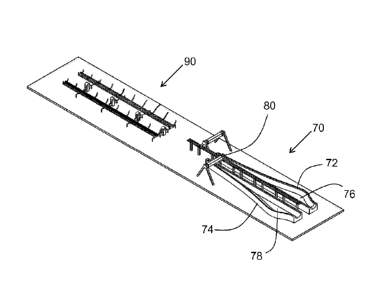
An embodiment of a manufacturing system for a wind turbine blade according to
the
invention is illustrated in Fig. 4. The manufacturing system comprises a blade
moulding
station (indicated at 70) and a post-moulding station (indicated at 90). The
blade moulding
station 70 comprises a set of first and second blade shell moulds 72,74. The
blade
moulds comprise respective first and second internal surfaces 76,78 which are
arranged
to produce first and second shaped blade shells having an aerodynamic profile
substantially corresponding to respective upwind (or pressure side) and
downwind (or
suction side) halves of a wind turbine blade.
During manufacture of a wind turbine blade, a lay-up operation is performed at
the blade
moulding station 70, wherein a plurality of layers of a preferably fibre-based
composite
material are applied to the internal surfaces 76,78 of the blade moulds 72,74.
The fibre
layers are applied to conform to the mould shape, and may be arranged at
various
thicknesses or densities dependent on the structural requirements of the wind
turbine
blade to be manufactured.
CA 02863290 2014-07-30
WO 2013/113815 PCT/EP2013/051898
In the embodiment shown in Fig. 4, the blade moulding station 70 is provided
with an
automatic fibre lay-up apparatus 80, which allows for machine-controlled lay-
up of the
layers of fibre-based material in the blade moulds 72,74. The automatic fibre
lay-up
apparatus comprises at least one fibre applicator device suspended on a
moveable gantry
5 provided above the blade moulds 72,74, the at least one fibre applicator
device operable
to move along the length of the blade moulds 72,74 to apply fibre layers, e.g.
fibre tape, to
the internal surfaces 76,78 of the blade moulds 72,74.
However, it will be understood that the manufacturing system of the invention
may be
10 implemented using any suitable lay-up mechanism, e.g. hand lay-up.
Furthermore, the
lay-up operation may comprise the use of pultruded elements or pre-pregs of
composite
material within the blade moulds, either as an alternative to or in addition
to the layers of
fibre-based material.
15 Once sufficient layers of the fibre-based material have been applied to
the surfaces of the
moulds 72,74, a curing operation is then performed to cure the fibre layers to
a relatively
hardened state. In one embodiment, this may comprise applying a cover or
vacuum bag
over the fibre layers to form a container, and subsequently applying a vacuum
pressure to
the interior of the container defined by the vacuum bag and the surface of the
blade
20 mould 72,74.
A curing resin is then infused or injected into the interior of the container,
the resin
spreading throughout the fibre layers by the action of the vacuum pressure.
The resin is
then allowed to cure and accordingly harden and join the layers of fibre-based
material
25 into a blade shell (not shown), having a structural profile
corresponding to the shape of
the surface of the blade moulds 72,74.
The term "cured blade shells" is used herein to refer to blade shells which
have been
substantially cured by the curing operation, preferably to a level where the
blade shells
can be handled without undergoing significant deformation of the shell
structure. The
duration of the curing operation performed will depend on the type of curing
resin used in
the manufacture of the blade shells, but may be of the order of 2-3 hours
using standard
resins. However, it will be understood that the blade shells themselves may
continue to
undergo a curing process within the body of the blade shells for several hours
after the
denoted curing operation.
CA 02863290 2014-07-30
WO 2013/113815 PCT/EP2013/051898
26
Accordingly, once the blade shells have substantially cured, the associated
cover or
vacuum bag may be removed, and the cured blade shells can be demoulded from
the
blade moulds 72,74. To demould the blade shells, any manufacturing equipment
which
may be provided above the blade moulds 72,74, e.g. automatic fibre applicator
device 80,
may be removed, and a lifting apparatus (not shown) may be positioned above
the blade
shells contained in the blade moulds 72,74. The lifting apparatus is operable
to lift the
cured blade shells out of the blade moulds 72,74, and to transfer the cured
blade shells to
the post-moulding station 90, where additional post-moulding operations may be
performed.
It will be understood that the transferring operation may be performed using
any suitable
lifting apparatus for the transferral of a wind turbine blade shell, e.g. a
vacuum lifting
device, a crane, a manual lifting operation, etc.
Examples of post-moulding operations which can be performed at the post-
moulding
station 90 on the blade shells can include, but are not limited to: a blade
shell repair
operation, involving a repair of any minor defects in a cured blade shell; a
blade shell
cutting or grinding operation, wherein a portion of a surface of the cured
blade shell can
be cut away or ground to present a relatively smooth profile; a blade root
flange coupling
operation, wherein a pair of blade root flanges which are provided on first
and second
blade shells are coupled together to form a single integral blade root flange;
a gluing
operation, wherein an adhesive is applied to a surface of a blade shell to
bond
components or blade shells together; a coating operation, wherein an external
surface of
a blade shell is coated with a coating layer, e.g. a gel coat or suitable
erosion resistant
material; a laminate installation operation, wherein a main laminate or other
element of the
interior of a wind turbine blade may be fixed to an internal surface of one of
the blade
shells for positioning in the interior of a wind turbine blade; an
overlamination operation;
installation of internal blade components, e.g. load or deflection monitoring
sensors,
lightning protection systems, etc.; a survey of blade shell geometry; a
secondary curing
operation in, for example, an oven; or any other suitable manufacturing or
assembly
operations.
As a result of performing these post-moulding operations at the post-moulding
station 90,
the blade moulds 72,74 are now released from the production time associated
with the
above post-moulding operations, which traditionally have been performed with
the blade
shells retained in the blade moulds 72,74. Accordingly, the use of a post-
moulding station
CA 02863290 2014-07-30
WO 2013/113815 PCT/EP2013/051898
27
90 to receive blade shells from a blade moulding station allows for the blade
moulds 72,74
to be freed up for a subsequent lay-up operation once the curing and
transferring of the
blade shells has been completed, and provides for reduced occupancy time of
the blade
moulds 72,74 by the components of a single wind turbine blade. This acts to
increase the
productivity of a single set of blade moulds 72,74, and provides for greater
flexibility in the
manufacturing process.
In the embodiment of Fig. 4, the post-moulding station comprises an open-
ribbed structure
to receive a cured blade shell from a blade moulding station, and to support
said cured
blade shells during post-moulding operations. With reference to Figs. 5-8, a
more detailed
view is provided of an alternate embodiment of a post-moulding station 100
according to
the invention.
The post-moulding station 100 of Figs. 5-8 comprises first and second blade
shell cradles
102,104 which are arranged to receive a cured blade shell after demoulding
from a blade
mould 72,74. The cradles 102,104 comprise substantially open-framed structures
or
cradle bodies 105 having respective tip ends 102a,102b and root ends
102b,104b, the
open-framed structures 105 having a plurality of support members 106 provided
thereon
to support the external surfaces of the cured blade shells.
The first blade cradle 102 is arranged to receive a first cured blade shell
corresponding to
an upwind or pressure side blade shell, and the second blade cradle 104 is
arranged to
receive a second cured blade shell corresponding to a downwind or suction side
blade
shell, wherein the support members 106 are configured to present a support
arrangement
appropriate for the characteristic dimensions of the blade shells, e.g. blade
length, blade
camber on the upwind and downwind surfaces, transition zones in the
aerodynamic profile
between different blade sections, etc.
The first and second cradles 102,104 are arranged in a parallel longitudinal
relationship,
the first cradle 102 coupled to the second cradle 104 via a plurality of
hinging mechanisms
108. With reference to Figs. 7 and 8, the first cradle 102 is arranged to be
hinged relative
to the second cradle 104, as indicated by the arrow X shown in Fig. 8(b), such
that the
first cradle 102 is positioned above the second cradle 104 to form a closed
post-moulding
station 100, as seen in Figs. 7(b) and 8(b). The post-moulding station 100 is
further
operable to translationally move the first cradle 102 relative to the second
cradle 104
when in the closed position, in order to correct the alignment between the
first and second
CA 02863290 2014-07-30
WO 2013/113815 PCT/EP2013/051898
28
cradles 102,104, as indicated by the arrows A and B in Fig. 8(b). The first
cradle 102 may
be moveable along the horizontal and/or vertical axis with respect to the
second cradle
104.
With reference to Fig. 5, the plan layout of the post-moulding station 100 is
substantially
symmetrical about the hinge axis Y, which extends through the plurality of
hinging
mechanisms 108. The first and second cradles 102,104 are connected to the
hinging
mechanisms 108 at the opposed sides 107 of the cradle bodies 105 corresponding
to the
leading edges of the blade shells to be received within the cradles 102,104.
Accordingly,
through the hinging of the first cradle 102 relative to the second cradle 104,
the sides 109
of the cradle bodies 105 corresponding to the trailing edges of the blade
shells to be
received within the cradles 102,104 are brought into close alignment.
With reference to the enlarged view of the root end of a post-moulding station
100 shown
in Fig. 9, the first and second cradles 102,104 each comprise opposed arrays
of side
support elements 106 located at the respective opposed leading edge side 107
and
trailing edge side 109 of the open-frame cradle body 105 of each cradle
102,104. The
cradles 102,104 each further comprise an array of support pads 110 provided on
the
cradle body 105, between the leading edge side 107 and the trailing edge side
109 of the
cradle body 105.
The array of side support elements 106 and the array of support pads 110
extend in a
longitudinal direction along the length of the cradle body 105, substantially
corresponding
to the length of the blade shell to be received in the cradle 102,104.
An embodiment of an individual side support element 106 is illustrated in
greater detail in
Fig. 10. The side support elements 106 each comprise a support main body 112
which is
provided on a pair of support legs 114 for attachment to the cradle body 105.
As
described above, the side support elements 106 may be moveable relative to the
cradle
body 105, preferably removable from the post-moulding station cradle 102,104,
to provide
easy access to a surface of a blade shell received within the cradle 102,104.
For example,
the side support elements 106 indicated in Fig. 9 may be removed from the
cradle body
105, to provide access to that portion of the leading or trailing edge of a
blade shell
supported by the indicated elements.
CA 02863290 2014-07-30
WO 2013/113815 PCT/EP2013/051898
29
With further reference to the enlarged views of Fig. 11, the support 106
comprises a
support main body 112 having a shell-facing surface 116 shaped to
substantially conform
to the external surface of a blade shell to be received in the post-moulding
station 100,
such that the shell-facing surface 116 of the support element 106 is provided
adjacent the
external surface of the blade shell when received in the post-moulding station
100.
A plurality of apertures 118 are defined in the shell-facing surface 116 of
the main body
112, wherein a series of vacuum clamp members 120 are received in said
plurality of
apertures 118. The vacuum clamp members 120 comprise a substantially circular
body,
and are linearly translatable relative to the main body 112 of the support
element 106, the
vacuum clamp members 120 coupled to linear actuators 122 located on the
opposite side
of the main body 112 to the shell-facing surface 116, as indicated in Fig.
10(b).
The vacuum clamp members 120 are actuatable from a first recessed position, as
indicated in Fig. 11(a), wherein the vacuum clamps 120 are positioned within
the
apertures 118 of the support element body 112 and do not substantially project
beyond
the shell-facing surface 116 of the main body 112, to a second advanced
position, as
indicated in Fig. 11(b), wherein the vacuum clamps 120 project proud of the
shell-facing
surface 116 of the main body 112. The vacuum clamp members 120 are operable to
apply a vacuum clamping pressure to the external surface of a blade shell
received within
the post-moulding station 100, to secure the blade shell within the cradles
102,104 of the
post-moulding station 100.
It will be understood that the side support elements 106 may have any suitable
configuration, e.g. the side support elements 106 might not comprise the
vacuum
clamping members 120 of the embodiment of Figs. 10and 11, i.e. the side
support
members 106 may be operable to simply support a blade shell received in the
cradles
102,104.
It will be understood that individual side support elements 106 may be
removable by
detaching the support main body 112 from the pair of support legs 114, to
provide access
to a surface of a received blade shell. Additionally or alternatively, the
entire side support
element 106, including the pair of support legs 114, may be removable from the
cradle
body 105, to provide said access.
CA 02863290 2014-07-30
WO 2013/113815 PCT/EP2013/051898
Additionally or alternatively, it will be understood that the side support
elements 106 may
be height adjustable, e.g. by variation of the height of the support legs 114,
wherein
access to a supported surface can be provided by adjusting the height of the
side support
element 106 in question. Additionally or alternatively, it will be further
understood that said
5 support main body 112 may be pivotably coupled to said support legs 114,
such that the
support main body 112 may be pivoted or hinged relative to said support legs
114, and
accordingly relative to an adjacent surface of a received blade shell, to
provide access to
said surface.
10 During use of the manufacturing system according to the invention, when
the post-
moulding station 100 is idle (i.e. not containing a blade shell) the vacuum
clamp members
120 are initially provided in the first recessed position, such that the
vacuum clamp
members 120 are safely protected from any damage by the main body 112 of the
support
element 106.
In a further preferred aspect of the invention, the vacuum clamp members 120
of the side
support elements 106 are operable to be moved relative to the cradle body 105
while a
vacuum pressure is applied to the surface of a blade shell received within the
cradle
102,104. This allows for minor adjustments to be made to the shape of the
external
surface of the blade shell, as the vacuum clamp members 120 are operable to
push
and/or pull the surface of the blade shell to which they are clamped to, to
deform the
blade shell into a desired profile or contour.
Returning to Fig. 9, the support pads 110 of the post-moulding station 100 are
operable to
be arranged to follow the aerodynamic profile of a blade shell to be received
within the
cradles 102,104.
In a preferred embodiment, for a particular construction of wind turbine
blade, the support
pads 110 are arranged on the cradle body 105 based on the profile of the wind
turbine
blade shell, to follow a nominal line corresponding to locations on the
external surface of
the blade shell matching the point of maximum distance from the external
surface of the
blade shell to the chord 60 of the wind turbine blade formed by said shell.
Such a nominal
line would correspond to the deepest section of the blade section received
within the
cradle 102,104. Such an arrangement thereby provides the most efficient
location for the
support pads 110 in the cradle 102,104, being arranged to support the lowest
points of
CA 02863290 2014-07-30
WO 2013/113815 PCT/EP2013/051898
31
the surface of the blade shell along the length of the blade shell when
received in the
cradle 102,104.
The support pads 110 are preferably moveable on the cradle body 105 between
the
leading edge side 107 and the trailing edge side 109 of the respective cradles
102,104.
For example, the support pads 110 may be provided on a lockable shuttle
element (not
shown) carried on at least one frame bar extending across the cradle body 105
between
the leading edge side 107 and the trailing edge side 109 of the cradle body
105.
Furthermore, the support pads 110 may be pivotably mounted to the respective
cradle
bodies 105, allowing for the orientation of the support pads 110 to be
adjusted as
required.
In a further aspect, the support pads 110 may be provided on a height-
adjustable arm (not
shown), such that the height of the support pads 110 relative to the adjacent
cradle body
105 surface may be varied. Accordingly, the location, orientation and/or
height of the
support pads 110 may be adjusted based on the aerodynamic profile of the blade
shells
to be received within the cradle 102,104. It will be understood that the
support pads 110
may comprise simple support units, and/or the support pads may comprise a
vacuum
clamping mechanism similar to that described in Figs. 10 and 11 for the side
support
elements 106.
With reference to Figs. 12-14, a post-moulding station 100 is shown when
having first and
second blade shells 122,124 received within said first and second cradles
102,104
respectively.
As a blade shell 122,124 is transferred to a cradle 102,104 of the post-
moulding station
100 from the blade moulding station 70, the external surface of the blade
shell 122,124
may initially rest upon the support pads 110 extending along the longitudinal
direction of
the cradle body 105. The blade shell 122,124 may also rest against a selection
of the side
support elements 106.
Preferably, as the cured blade shell 122,124 is formed in the blade moulding
station 70, a
blade root flange 126 is provided at the root end of the cured blade shells
122,124. The
blade root flange 126 comprises a substantially semi-circular metal flange
provided about
the end of the blade shell 122,124, and is used as the mounting point for the
finished wind
CA 02863290 2014-07-30
WO 2013/113815 PCT/EP2013/051898
32
turbine blade. The flange 126 comprises a plurality of bolt holes provided
about the
circumference of the flange 126.
In this preferred embodiment, the cradles 102,104 comprise at least one blade
root flange
coupling element 111 provided at the respective root ends 102b,104b of the
cradles
102,104. Accordingly, with reference to Fig. 14, as the cured blade shell
122,124 is
transferred to the appropriate cradle 102,104, the blade root flange coupling
element 111
is secured to the blade root flange 126 of the blade shell 122,124, to provide
an anchor
point for the blade shell 122,124 in the cradle 102,104.
In the case of wind turbine blades wherein the external blade shell 122,124 is
designed as
a load-bearing structure, as the root of the blade is designed to support the
weight of the
entire blade during normal operation, the blade root flange 126 provides an
effective
anchor and support point for the blade shell 122,124, at least during the
initial action of
transferring the blade shell 122,124 to the post-moulding cradle 102,104.
Furthermore, as
the coupling of the blade root flange 126 to the blade root flange coupling
element 111 of
the cradle 102,104 presents a defined location for a basic structural
component of the
blade shell 122,124, the location of the remaining surfaces and edges of the
blade shell
122,124 may be relatively easily predicted, e.g. the location of the tip end
102a,102b, and
the leading and trailing edges along the length of the shell.
Accordingly, the mounting of the blade root flange 126 to the cradle 102,104
allows for the
surfaces of the blade shell 122,124 and the support components of the post-
moulding
cradle, i.e. the side support elements 106 and the support pads 110, to be
relatively easily
aligned for effective support of the surfaces of the cured blade shell 122,124
by the cradle
102,104.
It will be understood that the blade root flange coupling element 111 may
comprise a
clamp arranged to couple with a blade root flange 16 of a cured blade shell
122,124.
Additionally or alternatively, the blade root flange coupling element 111 may
comprise a
bolt circle corresponding to a bolt circle defined on the blade root flange
126 of the blade
shell 122,124, to allow for bolting of the blade root flange 126 to the cradle
102,104.
In a preferred aspect, the main body 116 of the side support elements 106,
and/or the
support pads 110, are formed from a cushioned material which is operable to
prevent
CA 02863290 2014-07-30
WO 2013/113815 PCT/EP2013/051898
33
damage to the external surface of a blade shell 122,124 received in the cradle
102,104
when bearing against said external surface.
Once the cured blade shells 122,124 are secured within the cradles 102,104 via
the blade
root flange 126 coupling, the vacuum clamping members 120 of the side support
elements 106 and/or the support pads 110 are actuated to the said second
advanced
position bearing against the external surface of the blade shells 122,124, and
a vacuum
applied against the surface of the cured blade shells 122,124 to completely
secure the
shells in position in the cradles 102,104.
It will be understood that further securing mechanisms may be applied to
secure the blade
shells 122,124 within the cradles 102,104, e.g. mechanical clamps (not shown)
may be
applied from the cradles 102,104 about the edges of the shells 122,124 in the
cradles, to
provide a further securing effect.
At this point, as described above, suitable post-moulding operations may be
performed on
the blade shells 122,124, with direct access provided to the internal surfaces
(128, Fig.
14) of the blade shells 122,124 and access provided to portions of the
external surfaces
of the blade shells 122,124 via appropriate removal or adjustment of the
adjacent side
support elements 106 and/or support pads 110.
Examples of post-moulding operations which can be performed at the post-
moulding
station 100 on the blade shells 122,124 can include, but are not limited to: a
blade shell
repair operation, involving a repair of any minor defects in a cured blade
shell; a blade
shell cutting or grinding operation, wherein a portion of a surface of the
cured blade shell
can be cut away or ground to present a relatively smooth profile; a gluing
operation,
wherein an adhesive is applied to a surface of a blade shell to bond
components or blade
shells together; a coating operation, wherein an external surface of a blade
shell is coated
with a coating layer, e.g. a gel coat or suitable erosion resistant material;
a laminate
installation operation, wherein a main laminate or other element of the
interior of a wind
turbine blade may be fixed to an internal surface of one of the blade shells
for positioning
in the interior of a wind turbine blade; an overlamination operation;
installation of internal
blade components, e.g. load or deflection monitoring sensors, lightning
protection
systems, etc.; a survey of blade shell geometry; a secondary curing operation
in, for
example, an oven; or any other suitable manufacturing or assembly operations.
CA 02863290 2014-07-30
WO 2013/113815 PCT/EP2013/051898
34
In a preferred embodiment of the invention, the post-moulding station 100
further
comprises a rail or other suitable carriage mechanism (not shown) provided
along at least
one of the leading edge side 107 or the trailing edge side 109 of the cradle
body 105 of at
least one of the first and second cradles 102,104, wherein the rail is
operable to support
an automated tool for performing a post-moulding operation on a cured blade
shell
122,124 received in said cradle 102,104. An example of such a tool includes
but is not
limited to an automated grinding tool, for grinding a surface of a cured blade
shell
122,124, or an automated coating tool, for applying a coat to a surface of a
cured blade
shell 122,124.
Once the appropriate post-moulding operations are completed, an adhesive is
applied to
the leading edge and the trailing edge of at least one of the cured blade
shells 122,124.
The first cradle 102 is then hinged relative to the second cradle 104 using
the hinging
mechanisms 108, i.e. the post-moulding station is closed as shown in Fig.
8(b), such that
the contained first blade shell 122 is positioned in substantial alignment
with the second
blade shell 124 contained in the second cradle 104, as shown in Fig. 13. At
this point, the
first cradle 102 and the contained blade shell 122 may be translationally
moved, as
described in Fig. 8(b), to align the edges of the cured blade shells 122,124
and to correct
for any possible over- or under-bite between the shells after the hinged
closing operation.
A final translational movement of the first cradle may then be performed, to
close the first
and second blade shells 122,124 together to form a complete wind turbine
blade. The
cradles 102,104 and the contained shells 122,124 are maintained in the closed
arrangement of Fig. 13 until the adhesive has set to bond the first shell 122
to the second
shell 124. During the bonding time of the adhesive, the side support elements
106 are
operable to apply pressure against the sides of the contained blade shells
122,124, to
ensure that a correct adhesive bonding pressure is maintained at the leading
edge and
the trailing edge of the shells 122,124 to provide a strong and effective bond
between the
shells 122,124.
In addition, during the bonding time, the side support elements and/or the
support pads
may be removed or adjusted to provide access to sections of the external
surfaces of the
blade shells 122,124, to allow additional post-moulding operations to be
carried out on the
blade shells 122,124 while the cured shells are bonding together.
CA 02863290 2014-07-30
WO 2013/113815 PCT/EP2013/051898
The provision of a post-moulding station allows for the optimisation of a
manufacturing
system for a wind turbine blade, as the occupancy time of the relatively
expensive blade
moulds 70 can be minimised by transferral of cured blade shells to a post-
moulding
station 90,100 once the moulding of the shells has completed. Furthermore, the
flexible
5 open-framed structure of the post-moulding station 90,100 allows for
numerous
manufacturing operations to be relatively easily carried out on the cured
blade shells,
even during the bonding operation.
With reference to Fig. 15, an open-frame cradle body 105 for a post-moulding
station 100
10 is illustrated, minus the side support elements 106, support pads 110
and turning
mechanisms. As can be seen in Fig. 15(a), the cradle body 105 comprises an
open-
framed structure having a length substantially corresponding to the length of
the cured
blade shell to be received by the cradle. The cradle body 105 has a profile
which varies in
height and/or width, dependent on the profile of the cured blade shell to be
received in the
15 cradle. The cradle body 105 shown in Fig. 15(a) has a greater height in
the middle section
of the body 105 along the length of the body 105, accordingly the cradle body
105 shown
in Fig. 15(a) is suitable for receiving a pre-bent blade shell, in particular
a pressure side
shell of a pre-bent wind turbine blade. It will be understood that the
dimensions and profile
of the cradle body 105 may be varied as required to provide adequate support
for the
20 particular blade shell to be supported by the cradle.
With reference to Fig. 15(b), the cradle body 105 may be composed from a
plurality of
modular sections 130 assembled together to form the cradle body 105,
preferably a
plurality of modular steel trestles. The modular sections 130 may vary in
dimensions, e.g.
25 in section width and/or height, and are interchangeable such that the
structure of the
cradle body 105 may be varied dependent on the characteristics of the blade
shell to be
supported by the cradle, e.g. blade length, chord width, camber, etc.
The use of such a modular construction allows for a greater flexibility of the
overall
30 manufacturing system, as cradles can be easily constructed suitable for
different blade
designs, with individual cradles and modular sections re-used for different
manufacturing
processes.
While in the above embodiment of the invention an entire blade shell is
moulded using a
35 single blade mould, in a further alternative embodiment, the blade
shells 122,124 may be
manufactured as individual blade shell sections in separate blade moulds, the
individual
CA 02863290 2014-07-30
WO 2013/113815 PCT/EP2013/051898
36
blade shell sections provided for later assembly into a complete blade shell
or wind turbine
blade.
For example, a blade shell may be formed as a separate blade root section, a
blade tip
section, an intermediate aerodynamic section, etc., with each section
manufactured in a
separate blade mould designed to form that particular section of the blade
shell. The
individual sections may then be transferred from the different blade moulds to
a post-
moulding station as described above, wherein assembly of the different
sections can be
performed to form a complete blade shell, with subsequent closing and bonding
of the
complete blade shells to form the wind turbine blade.
Alternatively, the individual blade sections of the first and second blade
shells may be
closed and bonded before assembly into a complete wind turbine blade. i.e. the
upwind
and downwind blade root sections may be closed to form a complete blade root
portion,
the upwind and downwind blade aerodynamic sections may be closed to form a
complete
blade aerodynamic portion, etc., which can then be assembled to form the
complete
blade.
This may provide a further optimisation of the manufacturing process, as
individual
sections may be manufactured according to different requirements, e.g.
structural
requirements. In such a system, the post-moulding station of the invention
provides a
flexible and practical assembly bench for coupling the individual sections
together.
While the embodiment of Fig. 4 illustrates a manufacturing system wherein the
post-
moulding station is provided locally to the blade moulds, it will be
understood that
alternative arrangements of manufacturing systems may be provided. For
example, the
blade shells may be manufactured at a first location using blade moulds, as
described
above. The cured shells may then be demoulded, and transported to a post-
moulding
station provided at a relatively remote location for further manufacturing
operations and
eventual assembly. Such a system allows for the precision moulding of the
blade shell
parts to be conducted at a centralised location, using dedicated equipment and
a focused
workforce, with the relatively easier post-moulding and assembly tasks
performed at
distributed locations, e.g. adjacent a wind park under construction. This
approach
provides for a greater distribution of resources and a more efficient
manufacturing process
overall, combined with reduced transportation costs as readily stackable
shells may be
transported as opposed to finished wind turbine blades.
CA 02863290 2014-07-30
WO 2013/113815 PCT/EP2013/051898
37
An overview of the manufacturing process of the invention is provided in Fig.
16. Initially, a
fibre lay-up is performed in a blade mould (step 200). Such a lay-up operation
may be an
automatic or machine-controlled lay-up, or a hand lay-up operation. It will be
understood
that additional manufacturing operations may be performed at this stage, for
example the
blade mould may be coated with an initial layer of gel coat prior to the fibre
lay-up.
Once lay-up is complete, a vacuum bag is provided over the fibre layers in the
blade
mould (step 210). Once the bag forms a seal about the fibre layers, resin
infusion is
started (step 220), and a resin infused into the fibre layers in the mould.
The resin is
allowed to cure (step 230), to bond the fibre layers in the mould and to form
a cured blade
shell.
As described above, the actual blade shell may continue to cure within the
body of the
blade shell for several hours after the initial curing process, but it is
understood in the
context of this description that a cured blade shell refers to a blade shell
which has
undergone this initial curing step, and can be handled without experiencing
considerable
structural deformation.
Once cured, the vacuum bag is removed from the mould (step 240), and the cured
blade
shell can be removed or demoulded from the blade mould (step 250). This
demoulding
step may be performed using any suitable blade shell lifting device, e.g. a
crane or
vacuum lifting device.
At this point in the manufacturing process, as the cured blade shell has been
removed
from the blade mould, the blade mould may be re-used to form a second cured
blade
shell. Accordingly, the process branches off at this point, and loops back to
the initial fibre
lay-up step (200). As the blade moulds have a relatively low occupancy time,
the
production rate of the individual mould is increased, leading to improved
production times
for the entire manufacturing process. Furthermore, as the blade moulds are not
used for
post-moulding operations and/or turning operations, the blade moulds may be of
a simpler
construction, and/or comprise a structure which may be fixed to the factory
floor, e.g.
having concrete foundations, which provides for easier and cheaper manufacture
and
implementation of new moulds for a new manufacturing process.
CA 02863290 2014-07-30
WO 2013/113815 PCT/EP2013/051898
38
Once the cured blade shell has been demoulded from the blade mould, the shell
is
transferred to a post-moulding station according to the invention (step 260).
At this point,
the blade shell may be secured to the post-moulding station, e.g. through
coupling the
blade root flange of the blade shell to the root end of a cradle to receive
the blade shell,
the application of vacuum clamps against the external surface of the blade
shell, etc.
It will be understood that the process may further include a post-moulding
station
calibration step (not shown), prior to an initial transferral step 260. This
step may involve
the calibration of the cradles of the post-moulding station to receive the
blade shells, e.g.
through appropriate adjustment of the various cradle supports to ensure that a
blade shell
is securely received and supported in the cradle. In one approach, the
original master plug
used for the milling of the blade mould may be used to calibrate the cradle
supports, i.e. a
cradle may be positioned on the surface of the master plug, and the various
supports
adjusted to securely abut the surface of the master plug, thereby ensuring
that the
supports of the cradle match the corresponding support profile of the blade
mould in
question.
Once the shell is received in the cradle of the post-moulding station, various
post-
moulding operations as described above may be performed on the secured blade
shell
(step 270). These operations may be carried out on any surface of the cured
blade shell
via the open-framed structure of the cradle body, and through appropriate
removal or
adjustment of the support elements and/or support pads of the cradle.
In addition, imperfections in the cured blade shell may be corrected, e.g.
minor shape
adjustments may be made to the profile contours of the blade shell by securing
vacuum
clamps against the surface of the blade shell, and subsequently moving the
vacuum
clamps to accordingly push and/or pull the surface of the blade shell into a
preferred
profile.
Once the various post-moulding operations have been completed, the post-
moulding
station may be closed (step 280), such that a first cured blade shell may be
bonded with a
second cured blade shell to form a wind turbine blade.
In parallel to the time required for the adhesive between the two blade shells
to bond
effectively (step 290), various intra-bonding operations may be performed at
the post-
moulding station on the contained blade shells (step 300). Such operations may
include
CA 02863290 2014-07-30
WO 2013/113815 PCT/EP2013/051898
39
any manufacturing operations which may be applied on the shells during the
bonding
action, and may include any suitable post-moulding operations as described
above, e.g.
surface grinding, coating, etc. As with step 270, access may be provided to
the surfaces
of the blade shells through the open-framed structure of the cradle body, as
well as
through appropriate removal or adjustment of the support elements and/or
support pads
of the cradle.
The possibility to perform operations on the blade shells (step 300) in
parallel to the
bonding (step 290) provides for a further increase in the productivity of the
manufacturing
process, providing for less-down time of workers, equipment, etc., in
comparison to prior
art systems wherein a closing operation using turnable blade mould would
prevent any
access to the surfaces of the blade shells while the adhesive sets to bond the
shells
together.
Once the cured blade shells have bonded together to form a wind turbine blade,
the post-
moulding station may be opened and the completed blade removed from the post-
moulding station (step 310), for any finishing operations and subsequent
transport from
the manufacturing facility. It will be understood that any finishing
operations may be
performed while the completed blade is supported by the post-moulding station.
Once the completed blade is removed from the post-moulding station, the
process can
loop back to step 260, to receive a new cured blade shell at the post-moulding
station.
The manufacturing system of the invention provides for an improvement in
productivity
and effectiveness of the individual manufacturing components, and results in a
greater
efficiency of the blade manufacturing process, reducing ineffective down-time
of the blade
moulds, and providing a system where different manufacturing operations may be
performed in parallel which were traditionally performed in series.
It will be understood that various alternative arrangements and
implementations of
manufacturing processes may be considered. For example, in one alternative, a
manufacturing system is provided wherein a first blade mould performs a
turning
operation to demould a first contained cured blade shell onto an inverse blade
cradle (i.e.
when supported on the blade cradle, the external surface of the cured blade
shell faces
upwards). In this case, the post-moulding operations may performed on the
inverted shell.
A second cured blade shell may be lifted out of a second blade mould as
previously
CA 02863290 2014-07-30
WO 2013/113815 PCT/EP2013/051898
described, with the webs, etc., installed on the internal surface of the
second blade shell.
Accordingly, a lifting device is operable to lift the inverted first shell to
position it in place
on top of the second blade shell for bonding.
5 Some advantages of this approach include that the demoulding operation
may be
performed at same time for both blade shells, with only a single lifting
device required (i.e.
the second one shell is demoulded using the lifting device, while the first
shell is
demoulded using the hinging mechanism of the mould. Furthermore, the lifting
device can
be reused at the time of positioning the inverted first shell on top of the
second shell,
10 thereby increasing productivity of the lifting device.
In a further alternative, the blade cradles may be provided as a plurality of
separate,
discrete individual support components, which are each operable to support a
particular
point along the length of the blade shells. Advantages of this approach
include that the
15 separate components may be used as for example blade carts after the
bonding
operation, for easy local transportation of the bonded wind turbine blade.
Furthermore, the
individual components may provided for easier storage of the post-moulding
station, as
the individual components may be stored in a reduced-space location when not
in use.
20 The invention is not limited to the embodiment described herein, and may
be modified or
adapted without departing from the scope of the present invention.