Note: Descriptions are shown in the official language in which they were submitted.
INERTING DEVICE, TANK AND AIRCRAFT PROVIDED WITH SUCH A DEVICE, AND
CORRESPONDING METHOD
Field
The present invention relates to an inerting device, a tank and an aircraft
provided with
such a device as well as a corresponding method.
The invention relates more specifically to an inerting device for an aircraft
fuel tank of the
pressurized type, that is to say for a tank provided with a main vessel and
with a separate
overflow space.
Background
An inerting device may be used to protect a fuel tank, in particular of an
aircraft such as
a fixed-wing airplane or a helicopter, for example.
An inerting device replaces the gaseous headspace of a tank by a gas that is
enriched
with an inert gas (nitrogen), which can be produced by a generator such as an
"OBIGGS".
These tanks are generally connected to the exterior (the atmosphere) by means
of an overflow
space ("venting box"). The overflow space is a space which communicates with
the vessel of
the tank containing the liquid fuel, although this overflow space does not
contain any liquid fuel
under normal circumstances.
US Patent 8,074,932 relates to a system for the distribution of nitrogen-
enriched gas
inside an airplane tank that is subjected to ambient pressure. According to
this document,
during the descent phases of the airplane, nitrogen-enriched gas is injected
into a mixing
chamber situated between a communicating wing tank and an emergency reserve
tank. The
wing tank communicates with a central tank, while the emergency reserve tank
communicates
with the exterior by means of free openings. An oxygen sensor may be provided,
as
appropriate, within the wing tanks in order to ensure that the distribution
system is able to
determine whether the concentrations are acceptable.
This device is satisfactory to some extent, although it does not permit the
effective use of
the nitrogen-enriched air in all circumstances and it requires a mixing box
situated between two
remote tanks. The detection of the oxygen concentration is difficult,
moreover, and does not
provide data that are necessary in order to be able to ensure a concentration
of oxygen in the
entire tank. Finally, this architecture and this function are not well suited
to tanks under
pressure.
1
CA 2863359 2019-03-22
Summary
The invention relates more specifically to the tanks referred to as being
"under
pressure". That is to say that the overflow space communicates with the
atmosphere by means
of two orifices, each provided with a non-return valve ("check valve"). A
first "ascent" valve
opens in order to cause gas to exit from the tank only when the pressure
inside the overflow
space exceeds the atmospheric pressure by a predetermined value corresponding
to the
calibration of the valve. This makes it possible to limit the overpressure of
the overflow space
(and thus of the tank) in relation to the external pressure (in particular in
the event of the aircraft
as
A second "descent" valve opens in order to cause gas to enter the tank only
when the
atmospheric pressure exceeds the pressure inside the overflow space by a
predetermined value
corresponding to the calibration of the valve. This makes it possible to
maintain an
underpressure inside the overflow space (and thus inside the tank) in relation
to the external
pressure (in particular in the event of the aircraft descending).
Generally speaking, these tanks include a plurality of compartments separated
by baffles
provided with openings permitting the exchange of fluids. Ideally, the
nitrogen-enriched gas is
preferably injected into different parts of the tank, in such a way as to
homogenize as far as
possible the concentration of oxygen within the tank. However, the point of
injection of nitrogen-
enriched gas is subject to conflicting requirements. In fact, as the aircraft
ascends, a part of the
gas in the tank exits naturally towards the atmosphere as the atmospheric
pressure decreases.
Accordingly, in order to optimize the reduction in the concentration of
gaseous oxygen inside the
tank, the most appropriate point for injecting the nitrogen-enriched gas must
be as remote as
possible from the outlet office controlled by the ascent valve. Conversely,
during descent
phases of the aircraft (or phases of high fuel consumption), the atmospheric
air is admitted into
the tank via the descent valve and increases the amount of oxygen inside the
tank (up to 21%).
In this situation, the most appropriate point for injecting the nitrogen-
enriched gas must be as
close as possible to the outlet office controlled by the descent valve. These
two requirements
are thus contradictory.
One object of the present invention is to overcome all or some of the
disadvantages of
the prior art indicated above.
To this end, the device according to the invention, which furthermore complies
with the
generic definition provided by the above preamble, is characterized
essentially in that the device
comprises a generator for nitrogen-enriched gas, a circuit for transferring
the nitrogen-enriched
gas produced by the generator, the transfer circuit comprising an upstream
extremity connected
2
CA 2863359 2019-03-22
to the generator, a first downstream extremity which can be coupled to the
main vessel and a
second downstream extremity which can be coupled to the overflow space, the
device
comprising an array of sensors for the measurement of data that are
representative of the
pressure differential between, on the one hand, the interior of the overflow
space and, on the
other hand, the exterior of the tank, the device further comprising an
electronic logic for
receiving the measurements from the array of sensors, the electronic logic
being connected to
the generator and/or to the transfer circuit and being designed to control the
supply of a flow of
nitrogen-enriched gas to the second downstream extremity when the pressure
differential
between, on the one hand, the interior of the overflow space and, on the other
hand, the
exterior, falls below a predetermined threshold S.
Furthermore, embodiments of the invention may include one or a plurality of
the
following characteristics:
- the electronic logic is designed to control the supply of a flow of nitrogen-
enriched gas
to the second downstream extremity only when the pressure differential
between, on the one
hand, the interior of the overflow space and, on the other hand, the exterior
of the tank, falls
below the predetermined threshold,
- the second downstream extremity of the transfer circuit comprises a valve
for the
selective control of the flow of nitrogen-enriched gas intended to be supplied
to the overflow
space, the the valve being operated by the electronic logic,
- the first downstream extremity of the transfer circuit comprises a valve for
the selective control
of the flow of nitrogen-enriched gas intended to be supplied to the main
vessel, the the valve
being operated by the electronic logic,
- the first and second downstream extremities of the circuit are coupled in
parallel to the
upstream extremity of the circuit, the circuit comprising a three-way valve
for the selective
regulation of the flows of nitrogen-enriched gas originating from the
generator between the first
and the second downstream extremities, the three-way valve being operated by
the electronic
logic,
- one at least from among the upstream extremity, the first downstream
extremity and
the second downstream extremity of the transfer circuit comprises a non-return
valve for
preventing a movement of gas from downstream to upstream,
- one at least from among the first downstream extremity and the second
downstream
extremity of the transfer circuit comprises an orifice that is calibrated in
order to limit the flow of
gas to a predetermined value,
- the generator comprises a concentrator of the separation membrane type.
3
CA 2863359 2019-03-22
The invention likewise relates to an aircraft fuel tank of the pressurized
type, comprising
a main vessel intended to store liquid fuel and a separate overflow space, the
overflow space
being fluidly connected to the main vessel in order to absorb temporarily, but
without retaining
them, any overflows of liquid fuel from the main vessel, the overflow space
communicating with
the exterior of the tank by means of a system of two non-return valves having
opposite opening
directions, in which the fuel tank comprises an inerting device according to
any one of the
characteristics described above or below, the first downstream extremity of
the transfer circuit
being coupled to the main vessel and the second downstream extremity of the
transfer circuit
being coupled to the overflow space.
Furthermore, embodiments of the invention may include one or a plurality of
the
following characteristics:
- the overflow space communicates with the exterior of the tank via an inlet
valve
configured to open only when the pressure differential between, on the one
hand, the interior of
the overflow space and, on the other hand, the exterior of the tank, reaches a
predetermined
opening level, the electronic logic being designed to control the supply of a
flow of nitrogen-
enriched gas to the overflow space via the second downstream extremity when
the pressure
differential between, on the one hand, the interior of the overflow space and,
on the other hand,
the exterior and is between 70% and 100% of the the opening level,
- the electronic logic is designed to control the supply of a flow of nitrogen-
enriched gas
to the overflow space via the second downstream extremity when the pressure
differential
between, on the one hand, the interior of the overflow space and, on the other
hand, the exterior
of the tank, approaches 50 mbar or reaches the level that is sufficient for
the opening of the inlet
valve,
- the array of sensors for the measurement of data that are representative of
the
pressure differential between, on the one hand, the interior of the overflow
space and, on the
other hand, the exterior of the tank, comprises at least one pressure sensor,
- the transfer circuit is integrated into the generator and/or the reservoir,
- the second downstream extremity of the transfer circuit is coupled at the
level of a line
for venting the overflow space, that is to say at the level of a line
providing communication
between the overflow space and the exterior of the tank.
The invention likewise relates to an aircraft comprising a fuel tank according
to any one
of the characteristics described above or below, in which the array of sensors
for the
measurement of data that are representative of the pressure differential
between, on the one
hand, the interior of the overflow space and, on the other hand, the exterior
of the tank,
4
CA 2863359 2019-03-22
comprises at least one of the following: a sensor for the pressure
differential, a couple of
pressure sensors, a sensor for the altitude of the aircraft, a sensor for the
atmospheric pressure
around the aircraft, a sensor for the atmospheric temperature around the
aircraft, a sensor for
the rate of descent of the aircraft, a sensor for the fuel consumption of the
aircraft, a sensor for
the pressure of the inlet air supplying the generator for the purpose of its
enrichment with
nitrogen, a sensor for the temperature of the inlet air supplying the
generator for the purpose of
its enrichment with nitrogen, a sensor for the flow of nitrogen-enriched gas
at the outlet from the
generator, a sensor for the concentration of oxygen/nitrogen in the flow of
nitrogen-enriched gas
at the outlet from the generator, a sensor for the flow of nitrogen-enriched
gas at the outlet from
a buffer tank for storing the nitrogen-enriched gas produced by the generator,
a sensor for the
concentration of oxygen/nitrogen in the flow of nitrogen-enriched gas at the
outlet from a buffer
tank for storing the nitrogen-enriched gas produced by the generator.
The invention likewise relates to a method for inerting an aircraft fuel tank
of the
pressurized type, that is to say a tank provided with a main vessel and with a
separate overflow
space under pressure, inside which the inerting is achieved by means of an
inerting device
comprising a generator for nitrogen-enriched gas, the method comprising a
stage for the
determination of a pressure differential between, on the one hand, the
interior of the overflow
space and, on the other hand, the exterior of the tank, and, when this
pressure differential falls
below a predetermined threshold, a stage for the transfer of a flow of
nitrogen-enriched gas into
the overflow space.
The invention may likewise relate to any alternative device or method
comprising any
combination of the characteristics described above or below.
Hence, according to a broad aspect, the invention provides an inerting device
for a
pressurized aircraft fuel tank, the tank having a main vessel and a separate
overflow space, the
device comprising: a generator for nitrogen-enriched gas; a circuit for
transferring the nitrogen-
enriched gas produced by the generator, the transfer circuit comprising an
upstream extremity
connected to the generator, a first downstream extremity adapted to be coupled
to the main
vessel and a second downstream extremity adapted to be coupled to the overflow
space; an
array of sensors for measurement of data that are representative of a pressure
differential
between, on the one hand, a pressure of an interior of the overflow space and,
on the other
hand, a pressure of an exterior of the tank; and an electronic logic unit for
receiving
measurements from the array of sensors, the electronic logic unit being
connected to the
generator and/or to the transfer circuit and being designed to control a
supply of a flow of a
5
CA 2863359 2019-03-22
nitrogen-enriched gas to the second downstream extremity when the pressure
differential is
below a predetermined threshold.
According to another broad aspect, the invention provides a pressurized
aircraft fuel
tank, comprising: a main vessel adapted to store liquid fuel; a separate
overflow space, the
overflow space being fluidly connected to the main vessel to absorb
temporarily, but without
retaining, any overflow of liquid fuel from the main vessel, the overflow
space communicating
with an exterior of the tank via first and second non-return valves, the first
non-return valve only
allowing a flow of gas from the overflow space to an exterior of the tank and
being calibrated to
open only when a pressure of the overflow space is greater than a pressure of
the exterior of
the tank by a predetermined value associated with the first non-return valve,
the second non-
return valve only allowing a flow of gas from the exterior of the tank to the
overflow space and
being calibrated to open only when the pressure of the exterior of the tank is
greater than the
pressure of the overflow space by a predetermined value associated with the
second non-return
valve; and an inerting device for the pressurized aircraft fuel tank, the
inerting device
comprising: a nitrogen-enriched gas generator; a circuit for transferring a
nitrogen-enriched gas
produced by the generator, the transfer circuit comprising an upstream
extremity connected to
the generator, a first downstream extremity adapted to be coupled to the main
vessel and a
second downstream extremity adapted to be coupled to the overflow space; an
array of sensors
for measuring a pressure differential between the pressure of the overflow
space and the
pressure of the exterior of the tank; and an electronic logic unit for
receiving the measured
pressure differential from the array of sensors, the electronic logic unit
being connected to the
generator and/or to the transfer circuit, the electronic logic unit being
designed to control a
supply of a flow of the nitrogen-enriched gas to the second downstream
extremity when the
pressure differential is less than a predetermined threshold, the first
downstream extremity of
the transfer circuit being coupled to the main vessel and the second
downstream extremity of
the transfer circuit being coupled to the overflow space, the electronic logic
unit being designed
to control the supply of the flow of the nitrogen-enriched gas to the overflow
space via the
second downstream extremity when the pressure of the exterior of the tank is
greater than the
pressure of the overflow space by at least 70% of a predetermined value
associated with the
second non-return valve.
According to a further broad aspect, the invention provides a method for
inerting a
pressurized aircraft fuel tank, comprising: providing an aircraft with the
fuel tank, the fuel tank
comprising a main vessel adapted to store liquid fuel, a separate overflow
space, the overflow
space being fluidly connected to the main vessel to absorb temporarily, but
without retaining,
6
CA 2863359 2019-03-22
any overflow of liquid fuel from the main vessel, the overflow space
communicating with an
exterior of the tank via a first non-return valves and the second non-return
valve, the first non-
return valve only allowing a flow of gas from the overflow space to an
exterior of the tank and
being calibrated to open only when a pressure of the overflow space is greater
than a pressure
of the exterior of the tank by a predetermined value associated with the first
non-return valve,
the second non-return valve only allowing a flow of gas from the exterior of
the tank to the
overflow space and being calibrated to open only when the pressure of the
exterior of the tank is
greater than the pressure of the overflow space by the predetermined value
associated with the
second non-return valve; determining, with an electronic logic unit, a
pressure differential
between the pressure of the interior of the separate overflow space of the
fuel tank and the
pressure of the exterior of the tank; and allowing a flow of a nitrogen-
enriched gas from a
nitrogen-enriched gas generator into the overflow space via a second extremity
when the
pressure differential falls below a predetermined threshold and, with the
electronic logic unit,
allowing the flow of nitrogen-enriched gas to the overflow space from the
generator when the
pressure of the exterior of the tank is greater than the pressure of the
overflow space by at least
70% of a predetermined value associated with a second non-return valve; and
providing an
inerting device comprising the nitrogen-enriched gas generator; a circuit for
transferring the
nitrogen-enriched gas produced by the generator, the transfer circuit
comprising an upstream
extremity connected to the generator, a first downstream extremity adapted to
be coupled to the
main vessel and the second downstream extremity, a second downstream extremity
adapted to
be coupled to the overflow space, an array of sensors for measuring the
pressure differential
between the pressure of the overflow space and the pressure of the exterior of
the tank, the
array of sensors comprising at least one of the following: a sensor for the
pressure differential, a
couple of pressure sensors, a sensor for an altitude of the aircraft, a sensor
for an atmospheric
pressure around the aircraft, a sensor for an atmospheric temperature around
the aircraft, a
sensor for a rate of descent of the aircraft, a sensor for a fuel consumption
of the aircraft, a
sensor for a pressure of the inlet air supplying the generator for the purpose
of its enrichment
with nitrogen, a sensor for a temperature of the inlet air supplying the
generator for the purpose
of its enrichment with nitrogen, a sensor for the flow of the nitrogen-
enriched gas at the outlet
from the generator, a sensor for a concentration of oxygen/nitrogen in the
flow of the nitrogen-
enriched gas at the outlet from the generator, a sensor for the flow of
nitrogen-enriched gas at
the outlet from a buffer tank for storing the nitrogen-enriched gas produced
by the generator,
and a sensor for a concentration of oxygen/nitrogen in the flow of the
nitrogen-enriched gas at
the outlet from a buffer tank for storing the nitrogen-enriched gas produced
by the generator;
7
CA 2863359 2019-03-22
and wherein the electronic logic unit is connected to the generator and/or to
the transfer circuit,
the electronic logic unit being designed to control the supply of the flow of
the nitrogen-enriched
gas to the second downstream extremity when the pressure differential is less
than the
predetermined threshold, the first downstream extremity of the transfer
circuit being coupled to
the main vessel and the second downstream extremity of the transfer circuit
being coupled to
the overflow space.
Brief description of the figures
Other features and advantages will become apparent from a perusal of the
following
description, which is given with reference to the figures, in which:
- figure 1 depicts a schematic and partial view illustrating the structure
and the function
of an inerting device according to a first possible illustrative embodiment of
the invention,
- figure 2 depicts a schematic and partial view illustrating the structure and
the function
of an inerting device according to a second possible illustrative embodiment
of the invention,
- figure 3 depicts a schematic and partial view illustrating the structure and
the function
of an inerting device according to a third possible illustrative embodiment of
the invention,
- figure 4 depicts a schematic and partial view illustrating the structure
and the function
of an inerting device according to a fourth possible illustrative embodiment
of the invention,
- figure 5 depicts a schematic and partial view illustrating the structure and
the function
of an inerting device according to a fifth possible illustrative embodiment of
the invention.
Detailed description of embodiments
Variants, examples and preferred embodiments of the invention are described
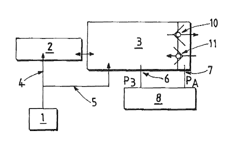
hereinbelow. Figure 1 illustrates an inerting device for a fuel tank of an
aircraft.
The tank of the aircraft comprises a main vessel 2 intended to contain the
liquid fuel and
a separate overflow space 3.
The overflow space 3 communicates fluidly with the main vessel 2 (the
communication is
symbolized by two arrows in the figure).
The overflow space 3 does not contain liquid fuel under normal circumstances
but is
able to absorb any overflows in the course of filling or during certain
movements.
The tank is of the "under pressure" type, that is to say that the overflow
space 3
communicates with the external atmosphere by means of two orifices, each
provided with a
non-return valve ("check valve" in English). A first "ascent" valve 10 opens
only when the
pressure inside the overflow space 3 exceeds the atmospheric pressure by a
predetermined
8
CA 2863359 2019-03-22
value corresponding to the calibration of the valve 10 (figure 1 includes an
arrow which
symbolizes the possible exit of the gas from the overflow space 3).
A second "descent" valve 11 opens only when the overflow atmospheric pressure
exceeds the pressure inside the overflow 3 space 3 by a predetermined value
corresponding to
the calibration of the valve 11 (figure 1 includes an arrow which symbolizes
the possible entry of
the gas into the overflow space 3). In this way, the system of valves 10, 11
maintains a
predetermined pressure (positive or negative) inside the overflow space 3 (and
inside the main
vessel 2).
Thus, when the aircraft is at a high altitude (for example above 4000 m), the
pressure
inside the tank is equal to the external atmospheric pressure plus the value
of the pressure
necessary to cause the ascent valve 10 to open. The descent valve 11 is
closed, and the ascent
valve 10 is open. When the aircraft begins to lose altitude, the pressure
within the tank reduces
progressively, the ascent valve 10 then closes and the two valves 10, 11 are
then closed.
During the descent, when the pressure inside the tank reaches the atmospheric
pressure less
the opening value of the descent valve 11, the latter opens and allows air to
enter.
The device comprises a generator 1 for nitrogen-enriched gas, for example a
membrane
separator and/or a nitrogen reserve under pressure any other appropriate
apparatus, and a
circuit 4, 5 for transferring the nitrogen-enriched gas produced by the
generator 1. The transfer
circuit 4, 5 comprises an upstream extremity connected to the generator 1, a
first downstream
extremity 4 coupled fluidly to the main vessel 2 and a second downstream
extremity 5 coupled
to the overflow space 3.
The nitrogen-enriched gas produced by the generator 1 is thus supplied
selectively and
simultaneously to the main vessel 2 and to the overflow space 3. The device
comprises an array
of sensors 6, 7 for the measurement of data that are representative of the
pressure differential
P3-Pa between, on the one hand, the interior of the overflow space 3 and, on
the other hand,
the exterior of the tank. The array of sensors is connected to an electronic
logic 8. The
electronic logic 8 is connected to the generator 1 and/or to the transfer
circuit 4, 5 and is
designed to control the supply of a flow of nitrogen-enriched gas to the tank
and, in particular, to
the overflow space 3 when the pressure differential P3-Pa between, on the one
hand, the
interior of the overflow space 3 and, on the other hand, the exterior, falls
below a predetermined
threshold S.
More specifically, the electronic logic 8 is thus able to determine the moment
when the
pressure inside the tank decreases and reaches a predetermined value that is
close or equal to
9
CA 2863359 2019-03-22
the value that is necessary to cause the descent valve 11 to open. This makes
it possible to
determine when air is entering or is about to enter the tank.
On the basis of these observations, the electronic logic 8 is able to control
the injection
of nitrogen into the tank at the moment when, or slightly before, the air
enters the tank.
For example, the descent valve 10 opens only when the external atmospheric
pressure
exceeds the pressure inside the tank by a value situated between 0.1 psi (689
Pa) and 5.0 psi
(34,474 Pa). For example, the injection of nitrogen into the overflow space 3
takes place when
the external atmospheric pressure exceeds the pressure inside the tank by a
value situated
between 0.1 psi (689 Pa) and 5.0 psi (34,474 Pa).
The array of sensors for the measurement of data that are representative of
the pressure
differential P3-Pa between, on the one hand, the interior of the overflow
space 3 and, on the
other hand, the exterior of the tank, may comprise, for example, at least one
pressure sensor.
For example, and as illustrated in figure 1, two sensors 6, 7 can measure the
pressure P3, PA
respectively inside the overflow space 3 and on the exterior of the tank. The
two sensors 6, 7
.. thus measure a pressure differential.
Of course, the array of sensors for the measurement of data that are
representative of
the pressure differential P3-Pa is not limited to this embodiment. The array
of sensors may thus
comprise at least one of the following: a sensor for the pressure
differential, a couple of
pressure sensors, a sensor for the altitude of the aircraft, a sensor for the
atmospheric pressure
around the aircraft, a sensor for the atmospheric temperature around the
aircraft, a sensor for
the rate of descent of the aircraft, a sensor for the fuel consumption of the
aircraft, a sensor for
the pressure of the inlet air supplying the generator for the purpose of its
enrichment with
nitrogen, a sensor for the temperature of the inlet air supplying the
generator for the purpose of
its enrichment with nitrogen, a sensor for the flow of nitrogen-enriched gas
at the outlet from the
generator, a sensor for the concentration of oxygen/nitrogen in the flow of
nitrogen-enriched gas
at the outlet from the generator 1, a sensor for the flow of nitrogen-enriched
gas at the outlet
from a buffer tank for storing the nitrogen-enriched gas produced by the
generator 1, a sensor
for the concentration of oxygen/nitrogen in the flow of nitrogen-enriched gas
at the outlet from a
buffer tank for storing the nitrogen-enriched gas produced by the generator 1.
In general, any device permitting the detection of the entry of air into the
tank or the
imminent entry of air due to a drop in relative pressure inside the tank in
relation to the exterior
may be utilized to control the supply of nitrogen-enriched gas to the overflow
space 3. In this
way, the device permits the level of oxygen inside the tank to be prevented
from rising before
and/or during the entry of air into the overflow space 3.
CA 2863359 2019-03-22
Figures 2 to 5 illustrate possible variant embodiments of the invention. In
the interests of
brevity, the elements that are identical to those described above are
designated by the same
numerical references and are not described for a second time.
The embodiment depicted in figure 2 differs from that in figure 1 solely in
the sense that
the second downstream extremity 5 of the transfer circuit comprises a valve 15
for the selective
control of the flow of nitrogen-enriched gas that is intended to be supplied
to the overflow space
3. The the valve 15 is preferably operated by the electronic logic 8 in order
to control the
enriched gas supplied to the overflow space 3. The valve is of the all-or-
nothing type or
proportional. In this way, the nitrogen-enriched gas is always injected into
the main vessel 2,
although the injection into the overflow space 3 only takes place when it is
necessary (during or
before an entry of air).
The embodiment in figure 3 differs from that in figure 1 solely in the sense
that the first
downstream extremity 4 of the transfer circuit comprises a valve 14 for the
selective control of
the flow of nitrogen-enriched gas that is intended to be supplied to the main
vessel 2. This valve
14 (of the all-or-nothing type or proportional) is preferably operated by the
electronic logic 8.
In this way, the nitrogen-enriched gas is always injected into the overflow
space 3,
although the injection into the main vessel 2 only takes place when this is
required.
In the embodiment depicted in figure 4, the first 4 and the second downstream
extremity
5 each include a respective control valve 14, 15. This makes it possible to
control the quantities
of nitrogen-enriched gas that are supplied independently to the main vessel 2
and to the
overflow space 3.
According to the embodiment depicted in figure 5, a three-way valve 9 is
provided in the
circuit for the selective regulation of the flows of nitrogen-enriched gas
originating from the
generator 1 between the first 4 and the second 5 downstream extremities. This
three-way valve
9 preferably does not permit the supply of nitrogen-enriched gas at the same
time to the two
downstream extremities, but to one or the other alternately.
The structural characteristics of the above embodiments may be combined where
appropriate.
Similarly, for each of the above embodiments, it is possible to provide a non-
return valve
at the first downstream extremity 4 and/or the second downstream extremity 5
of the transfer
circuit, so as to prevent movement of the gas from downstream to upstream.
Furthermore, a calibrated orifice may be provided on the first downstream
extremity 4
and/or on the second downstream extremity 5 of the transfer circuit in order
to restrict the flow of
gas to a predetermined value.
11
CA 2863359 2019-03-22
In addition, the transfer circuit may be integrated physically into the
generator 1 and/or
the tank.
According to another possible feature, the second downstream extremity 5 of
the
transfer circuit may be coupled at the level of a venting line for the
overflow space 3, that is to
say at the level of a line providing communication between the overflow space
3 and the exterior
of the tank.
12
CA 2863359 2019-03-22