Note: Descriptions are shown in the official language in which they were submitted.
CA 02863368 2014-07-30
WO 2013/116368
PCT/US2013/023897
MANAGING BACK PAIN BY APPLYING A HIGH FREQUENCY ELECTRICAL
STIMULUS DIRECTLY TO THE SPINAL CORD
REFERENCE TO RELATED APPLICATIONS
[0001] This application claims the priority benefit of U.S. provisional
application 61/592,520
filed January 30, 2012. The priority application and published PCT application
WO 2012/065125
are hereby incorporated herein by reference in their entirety for all
purposes.
FIELD OF THE INVENTION
[0002] The invention relates generally to the field of medical devices and
pain management.
In particular, it relates to structures, electrode arrays and electronics for
applying high frequency
electrical stimulation to the spinal cord
BACKGROUND
[0003] Chronic pain is an often unbearable sequelae of spinal cord injury
or disease. It can
interfere with the basic activities, effective rehabilitation, and quality of
life of the patient. Pain in
the cord-injured patient is often recalcitrant to treatment. This problem is
amplified by the limited
availability of effective pharmacological and nonpharmacological treatment
options.
[0004] The prevalence of pain in patients with spinal cord injury is high:
in some studies
ranging from about 62% to 84% of patients. Back pain is also a feature of
other injuries and
conditions. For example, postural abnormalities and increased muscle tone in
Parkinson's disease
may cause back pain, were the prevalence can be as high as 74%. Other
conditions associated with
back pain include congestive heart failure and osteoartlu-itis.
[0005] Because back pain is often intractable within the current spectrum
of clinical
modalities, there is a need for new technology designed for pain management.
SUMMARY OF THE INVENTION
[0006] This invention provides a new technology for applying a stimulus
directly to the
surface of the spinal cord from within the spinal canal. The stimulus
alleviates symptoms and signs
of back pain, while minimizing the risk of side effects such as paresthesia.
[0007] One aspect of the invention is a method, a device, and a system for
stimulating a spinal
cord of a subject who is prone to deleterious nerve signals transmitted along
the spinal cord. The
method comprises implanting an electrode array within the spinal canal of the
subject so that the
electrodes engage the spinal cord; and then applying an electrical stimulus
through the electrodes in
1
CA 02863368 2014-07-30
WO 2013/116368
PCT/US2013/023897
the array directly to the spinal cord so that the electrical stimulus inhibits
transmission of the
deleterious nerve signals along the spinal cord. The electrical stimulus has a
sufficiently high
frequency to inhibit paresthesia.
[0008] Another aspect of the invention is a method for stimulating the
spinal cord of a subject
so as to inhibit pain transmission. The method comprises applying through a
plurality of electrodes
directly in contact with the spinal cord an electrical stimulus so as to
render sensory neurons within
the spinal cord refractory to transmission of synchronous action potentials
initiated within the spinal
cord.
[0009] Another aspect of the invention is a device for stimulating the
spinal cord of a subject
so as inhibit pain transmission. The device can comprise the following
components: (a) a compliant
backing configured to conform to a region of the spinal cord within the dura;
(b) a plurality of
electrodes arrayed along the inner surface of the backing; and (c) circuitry
for delivering an
electrical stimulus to the spinal cord through the plurality of electrodes,
thereby rendering sensory
neurons within the spinal cord refractory to transmission of synchronous
action potentials initiated
within the spinal cord.
[0010] Another aspect of the invention is a system for stimulating the
spinal cord of a subject
so as to inhibit pain transmission. The system can comprises the following
components: (a) an
implantable signal receiver configured to conform to a surface of a region of
the spinal cord, the
transceiver having a plurality of contacts configured for electrical coupling
to corresponding
positions in said region; and (b) a signal generator comprising a
microprocessor programmed to
generate an electrical stimulation signal. The receiver can be configured to
receive said signal from
the signal generator, and to transmit the signal to the corresponding
positions in said region of the
spinal cord. This can render sensory neurons within the spinal cord refractory
to transmission of
synchronous action potentials initiated within the spinal cord.
[0011] Another aspect of the invention is a system for stimulating the
spinal cord of a subject
who is prone to deleterious nerve signals transmitted along the spinal cord.
The system can
comprise the following components: (a) an electrical stimulation device
including a compliant
backing configured to conform to a region of the spinal cord, and an
electrical stimulation surface
disposed within an inner surface of the backing, the electrical stimulation
device configured to be
implanted within dura of the subject so that the stimulation engages the
spinal cord; and (b) a signal
generator coupled to the electrical stimulation surface. The generator may be
microprocessor
controlled, and is configured and programmed to apply an electrical stimulus
from the electrical
stimulation surface directly to the spinal cord with a sufficiently high
frequency to inhibit manifest
stimulation-induced paresthesia.
[0012] In any of these methods, devices, or systems, the electrical
stimulus is intended to
promote stochastic depolarization of sensory neurons within the spinal cord.
It may have a potential
that alternates at high frequency, such as 1,000 to 9,000 Hertz. The
electrical stimulus can have a
2
CA 02863368 2014-07-30
WO 2013/116368
PCT/US2013/023897
potential that varies according to a non-uniform pattern, or that varies at
stochastic intervals. It can
be administered to the spinal cord through an array of 10 or more electrodes
in direct contact with
the spinal cord. The device can be configured so that different stimuli are
conveyed through
different electrodes in the array.
[0013] A device or system of this invention may also have a means for
monitoring
transmission of synchronous action potential through the spinal cord, and a
means for adjusting the
electrical stimulus so as to further inhibit transmission through the spinal
cord of synchronous action
potentials. Thus, the user may monitor transmission of synchronous action
potential through the
spinal cord, and adjust he electrical stimulus so as to further inhibit
transmission through the spinal
cord of synchronous action potentials. The stimulus can be applied so as to
inhibit sensation of pain,
or to inhibit symptoms of Parkinson's disease, spinal cord injury, or
congestive heart failure.
[0014] Other aspects of the invention will be apparent from the description
that follows.
DRAWINGS
[0015] Figure 1 is a schematic depiction of an electrode in cross-section,
extending from the
backing upon which it is arrayed.
[0016] Figure 2 shows electrodes arrayed in the backing so as to provide a
degree of mobility.
[0017] Figure 3(A) and (B) depict an electrode array implanted onto a
spinal cord. Lead 202
passes out of the spinal canal to bring power and control signals to the
array.
[0018] Figure 4(A) and (B) show details where the lead is adapted to pass
through the dura.
Figure 4(C), (D), and (E) show the fitting being installed and glued into
place to prevent leakage
across the dura.
[0019] Figure 5 shows an electrode array that has been adapted to receive
power and control
signals wirelessly.
[0020] Figure 6 is an oblique view of the wireless array implanted onto the
spinal cord.
[0021] Figure 7 is a transverse view of the array after implantation, with
the dura cut away.
[0022] Figure 8 is a longitudinal cross-section of the spinal cord with the
implanted array.
The shaded rings represent electrical stimuli coming downward from the array
to the region targeted
for treatment.
[0023] Figure 9 is a schematic representation of the inductive coupling
between the
transmitter providing power and control signals, and the receiver coils
adjacent to the electrode
array.
[0024] Figure 10(A) and (B) show an electrode array configured for
attachment to the spinal
cord in a wrap-around configuration.
3
CA 02863368 2014-07-30
WO 2013/116368
PCT/US2013/023897
[0025] Figure 11 illustrates a device that can be used by the neurosurgeon
to implant the
wrap-around electronic array into a spinal cord.
[0026] Figure 12 represents a cross-sectional view of the human spinal cord
and surrounding
tissue.
[0027] Figure 13 shows an electrode array configured to be clamped to the
dentate ligament
on each side of the spinal cord. The inset shows a detail of a clip that
affixes an extension of the
array to the ligament.
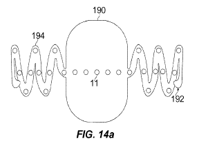
[0028] Figure 14(A) and (B) show another electrode array configured for
attachment to the
dentate ligament. In this case, the clasp or tab for affixing the array is a
further extension of the
array's backing material.
DETAILED DESCRIPTION
[0029] This invention provides a new technology for management of back
pain, leg pain, and
other conditions by stimulating the spinal cord in a manner that renders it
refractory to transmission
of deleterious or undesirable sensory input. The electrical stimulus comprises
high frequency pulses
in a regular or complex pattern or that are stochastically produced under
microprocessor control.
The stimulus is applied directly to the surface of the spinal cord from within
the spinal canal, which
provides important benefits over previous technology. The stimulus alleviates
symptoms and signs
of back pain, while inhibiting or minimizing the risk of side effects such as
paresthesia, and
potentially minimizing any side effects on essential neurological processes
such as motor neuron
transmission and proprioception.
Rationale
[0030] This section discusses certain neurophysiological phenomena that may
underlie some
of the benefits of this invention. The discussion is provided for the benefit
of the reader and to help
advance the art. It should not be interpreted as imposing any limits on the
practice of the invention.
The reader may implement and advance the devices and methods of this invention
without
understanding or proving any of the phenomena propounded here.
[0031] High frequency stimulation of the spinal cord may benefit the patent
by inducing a
state of pseudospontaneous axon firing. Bundles of sensory axons are thought
to fire randomly
when not transmitting sensory stimulus. When a sensory stimulus is presented,
a substantial
proportion of the axons within a bundle or pathway will discharge in a
synchronous fashion ¨ firing
axons potentials at about the same time. This results in the sensory input
being transmitted along the
axons in the bundle, so that the subject may experience the sensation. Stated
differently, the absence
4
CA 02863368 2014-07-30
WO 2013/116368
PCT/US2013/023897
of sensation is coded by random timing of axon firing within a bundle, whereas
a sensory perception
is coded by synchronous firing of a population of axons.
[0032] It is a hypothesis of this invention that patients with leg and back
pain have bundles of
axons spontaneously firing in a synchronous manner (or some other non-random
fashion), instead of
the normal random pattern of firing. Electrical pulses will entrain axonal
firing. A single pulse
delivered to a bundle of axons will cause them all to fire synchronously. If
the time interval
between each electrical shock in a pulse train is longer than the refractory
period of the axons in the
bundle, each subsequent shock will also synchronously activate all of the
axons, and a subject will
experience a sensation. A low frequency alternating current applied to the
back (50 Hz) may be
effective in reducing the sensation of pain, but the stimulation may generate
neurological side
effects such as paresthesias (tingling or numbness).
[0033] A high frequency electrical stimulus (say, about 5,000 Hz) has
interval spacing shorter
than the refractory period of axons. An individual axon cannot fire again in
response to a second
shock until its membrane potential has recovered from the effects of the first
shock, and this takes
time. Different axons have different refractory periods. By delivering
electrical pulses at high
frequency, the relative timing of firing by individual axons within the bundle
of axons becomes
nearly random, with different axons become excitable again at different times.
Applying high
frequency pulses to the spinal cord can be used to restore a state of active
quiescence in the sensory
nerves passing through the cord.
[0034] "Quiescence" as the term is used in this disclosure in reference to
a bundle of axons
refers to a condition of stochastic depolarization or firing of axons within
the bundle. It is a natural
condition in which the neurological system may be actively signaling that
there is no sensory input
to be transmitted by the bundle as a whole. It may be induced by
pseudospontaneous neural
stimulation by applying effective high-frequency electrical pulse patterns in
an appropriate manner
as described here.
Benefits
[0035] This invention provides a new technology whereby high frequency
electrical stimulus
is applied directly to the spinal cord. It represents an important advance in
the management of back
pain, because targeted axons can be subject to an electrical stimulus without
exposing the dorsal
rootlets to suprathreshold levels of current.
[0036] Besides providing the clinician with new modalities for pain
management, attributes of
the technology include the following:
[0037] 1) Low power consumption. Because the devices of this invention
delivers stimuli
directly to the spinal cord, the power consumption is lower compared with
devices used to treat back
pain from outside the spinal canal. The power required by a device of this
invention may be as low
CA 02863368 2014-07-30
WO 2013/116368
PCT/US2013/023897
as 30%, 10%, or even 5% or less of what is required by a standard extra-dural
electrode. In some
embodiments, devices of this invention implanted with a battery power source
may provide pain
relief for several days, often for a week or much more.
[0038] 2) Variable waveforms and frequencies. Because of the effects of
cerebrospinal fluid
(CSF) and other soft tissues, a high frequency square waveform delivered
through these tissues will
be significantly attenuated and distorted by the time the electrical pulses
reach the spinal cord. The
pulses reaching the spinal cord will have a different spectral composition,
i.e., be a different
waveform with potentially different frequency components. Electrical
stimulation from the devices
of this invention should not be distorted and attenuated to this extent,
because there is no intervening
fluid or tissue between the stimulating electrode and the targeted axons.
Varying the amplitude of
the pulses according to a complex pattern or in a stochastic fashion may be
more effective when
delivered directly to the spinal cord.
[0039] 3) Penetration into the spinal cord. A direct contact electrode
array according to this
invention may allow the user to apply stimulation much deeper into the spinal
cord (more than 0.5 or
1.0 mm below the surface). This compares with standard extra-dural electrodes,
which may be
effectively limited to altering signal transmission adjacent the spinal cord
surface adjacent the
anterior dura. As nerve signals may be transmitted, at least in part, by
neurons at a range of depths,
this may facilitate treatment of conditions that are less amenable to
treatment using other
technology.
[0040] 4) Spatially selective stimulation. Normal spinal cord signaling is
essential to allow a
subject to sense the ground and move their legs. The neural pathways required
involve populations
of axons that fire synchronously. For this reason, if an electrical stimulus
interfered indiscriminately
with the coordination of action potentials within the spinal cord (for
example, delivering the
stimulus epidurally), the treated subjects may have deficits in proprioception
and kinesthesia. This
in turn may cause stumbling or gait abnormalities. The technology of this
invention helps avoid this
problem by more precisely targeting the neurological pathways that transmit
the sensation of pain.
Specifically, the device is deployed on the lateral surface of the spinal
cord, and so is proximal to
white matter of the spinal cord. In addition, the electrode arrays can be
placed strategically to
maximize any trade-off between pain relief and interference with neural
pathways transmitting
essential information.
Particular features of the invention
[0041] This invention generally provides a method for stimulating a spinal
cord of a subject,
such as may be clinically desirable in pain management or the treatment of
several other medical
conditions. The patient is prone or susceptible to deleterious nerve signals
transmitted along the
spinal cord, or otherwise requires treatment. An electrode array is implanted
within the spinal canal
6
CA 02863368 2014-07-30
WO 2013/116368
PCT/US2013/023897
so that the electrodes engage the spinal cord. An electrical stimulus is
through the electrodes in the
array directly to the spinal cord so as to inhibit transmission of the
deleterious nerve signals along
the spinal cord. The electrical stimulus has a sufficiently high frequency to
inhibit sensory side
effects such as paresthesia (numbness or tingling).
[0042] Put another way, the spinal cord is stimulated so as to inhibit pain
transmission by
applying directly to the spinal cord an electrical stimulus that renders
sensory neurons refractory to
transmission of synchronous action potentials initiated within the spinal
cord. This inhibits back
pain from locally induced sensory input, and side effects such as paresthesia
that may be induced in
the course of local treatment. The electrical stimulus is thought to promote
stochastic depolarization
of sensory neurons within the spinal cord, thus inducing a state of neural
quiescence.
[0043] To accomplish this, the electrical stimulus comprises a potential
that alternates at high
frequency. Regardless of the way the potential may vary over time, the
frequency may be calculated
by determining the number of positive-to-negative alterations per unit time.
Effective frequency
ranges depend on place of placement of the electrode array, the features of
the array, the nature and
health of the tissue where the array is placed, and the objectives of
treatment. The general object is
to induce refractoriness of the spinal cord to transmit deleterious signals or
synchronous
depolarization events initiated locally. This can be adjusted empirically by
determining neural
activity and recording the symptoms experienced by the patient.
[0044] Depending on the objective of the treatment and the manner in which
the technology is
deployed, effective pulse repetition rates or frequencies may be at or above
100 Hz (pulses per
second), 200 Hz, 500 Hz, 2,000 Hz, or 5,000 Hz, a frequency of about 1,000 Hz,
4,000 Hz, or
10,000 Hz, or a frequency range of about 500 to 50,000 Hz, 1,000 to 9,000 Hz,
3,000 to 8,000 Hz,
2,000 to 20,000 Hz, or 5,000 to 15,000 Hz.
[0045] The electrical potential may vary at a regular frequency in a
sinusoidal or square wave
form. Alternatively, the wave form may be a more complex pattern, with pulses
appearing at
varying intervals and intensities according to a calculated or repetitive
pattern. Such patterns
comprise a pulse train generating substantially continuous activation of
nerves within the spinal
cord, and may incorporate irregular pulse intervals, irregular pulse
amplitudes, a variety of wave
forms (for example, monophasic, biphasic, rectangular, sinusoidal, as well as
asymmetric or
irregular wave forms), or any combination thereof The potential may create
what is essentially a
broad band noise, varying at stochastic or essentially random intervals and
intensity under the
influence of a suitable computational algorithm or automated control program
in a microprocessor.
[0046] Further information on pseudospontaneous neural stimulation is
described in U.S.
Patent Nos. 6,295,472 and 6,631,295, and JT Rubenstein et al., Hearing Res.
127(1), 108-118,
1999, which are hereby incorporated herein by reference in their entirety for
all purposes.
[0047] The electrodes through which the high-frequency stimulus is conveyed
are typically
arrayed on a pliable background, constructed of a material and in a shape that
allows it to be
7
CA 02863368 2014-07-30
WO 2013/116368
PCT/US2013/023897
conformed directly to the spinal cord. The plurality of electrodes may
comprise at least 10, at least
20, at least 30, or at least 50 electrodes. They may be arrayed on the backing
in a grid, a rectilinear
pattern, or any other arrangement that is effective. Optionally, the
technology may be configured to
apply different stimuli through different electrodes in the array.
[0048] Treating back pain according to the invention may comprise
administering an effective
electronic stimulus to the spinal cord, monitoring transmission of synchronous
action potential
through the spinal cord, and then adjusting the electrical stimulus so as to
further inhibit
transmission through the spinal cord of synchronous action potentials. The
object may be anything
that is clinically worthwhile, such as reducing sensation of pain (especially
back pain) by the
subject, such as may occur in the course of spinal cord injury, disease or
strain of the spinal cord,
Parkinson's disease, osteoarthritis, or congestive heart failure.
[0049] The electrical stimulus may be adjusted in frequency or other
waveform parametersõ
and manner of application so as to minimize side effects such as paresthesia,
and to minimize impact
on transmission of essential neurological faction, including motor neuron
activity, and nerves
involved in proprioception and kinesthesia. Optionally, the clinician or the
user may be provided
with an input means to select the pattern, adjust the frequency, and adjust
the intensity in accordance
with the perceived symptoms.
[0050] The devices and systems of the invention also have circuitry
configured to deliver an
electrical stimulus to the spinal cord through electrodes. The circuitry may
be built into the same
backing as the electrodes. Power and control signals can be provided to the
circuitry and the
electrodes by electrical leads that pass out though the dura. Alternatively,
the device may have a
receiving means such as an antenna through which to receive power and control
signals wirelessly
from an external source. A "one size fits all" design is desirable, whereby a
standard device can
accommodate almost the full range of spinal cord anatomy variants encountered
in patients. When
this is not practicable, the electrode array and the features for securing on
or about the spinal cord
can be built in different sizes to suit different patients.
Techno1o2y platform
[0051] The invention described here incorporates features that are also
described in
WO 2012/065125. That application provides devices for direct spinal cord
stimulation that are
remotely controlled and laterally supported. For the electrode array to be
implanted in the spinal
cord for use on an ongoing basis, the device is secured so that it maintains
direct contact with the
desired region of the spinal cord.
[0052] The technology platform provides an advance over previous devices
and methods in
pain management in a number of respects. Included are the following:
8
CA 02863368 2014-07-30
WO 2013/116368
PCT/US2013/023897
= a dense array of electrode contacts delivers highly localized, spatio-
temporally
synchronized, and positionally selective electrical stimuli to any targeted
region of the
spinal cord;
= the implantable electrode assembly has an ultra-thin physical profile
that does not
obstruct or alter flow patterns of cerebrospinal fluid (CSF) around the spinal
cord;
= the contact forces between the device and the spinal cord are stable and
unvarying, and
hence patient movement does not affect these contact properties, which results
in
optimal electrical coupling between electrode contacts and spinal cord tissue;
= the compliant nature of the device materials accommodates pulsations of
the spinal
cord without any harmful reactive or dissipative counter-forces;
= the surgical procedure used to implant the device is well established and
safe, and when
performed by skilled practitioners, the risk of CSF fistula formation with
this procedure
is minimal, and can potentially be done in 30 minutes;
= manufacture of the device is uncomplicated and cost-effective.
Aspects of this technology are illustrated in Figures 1 to 14, and described
below.
[0053] Figure 1 schematically illustrates an electrode projecting from an
interior surface of a
backing or substrate. Therapeutic benefit may be enhanced by maximizing
current densities in the
targeted conducting tracts of the spinal cord itself, while minimizing the
current density shunted
away by the CSF. The electrodes are engaged against the surface of the spinal
cord as shown, with a
stand-off column 220 extending between the exposed portion of the electrode 34
and the underside
of the implant substrate body 222. This can support the implant off the
surface of the spinal cord by
about 100 lam to accommodate pulsation of the spinal cord 22. By insulating
the surface of stand-
off column 220, it is possible to minimize the shunting effect of the CSF,
since the exposed portion
of the electrode will be in contact only with the pial surface 24 of the
spinal cord, and not with the
CSF itself Gentle inward pressure causes slight inward "dimpling" of the pial
surface by the
electrode. As a result, the active exposed surface of the electrode is
"sealed" by spinal cord tissue
enveloping the protruding portion of the contact. A small gap separates the
electrically inactive
portions of the array, providing space into which the spinal cord tissue may
expand and contract
with cardiac pulsation cycles.
[0054] Figure 2 schematically illustrates individual electrodes 34 flexibly
mounted to a
backing or substrate 230 by a soft resilient material 232 so as to allow the
electrode to resiliently
float or move radially and/or laterally relative to the substrate by a
distance that is at least as large as
the pulsations of the surface 24 of spinal column 22. This movement of each
electrode may inhibit
sliding engagement of the electrodes against the surface of the spinal cord
during pulsation. In some
implementations, the only parts of the array that directly engage the spinal
cord are the electrode
contacts. These may serve as mechanical anchoring points for the device. They
exert enough
9
CA 02863368 2014-07-30
WO 2013/116368
PCT/US2013/023897
pressure to maintain good electrical contact with the surface of the spinal
cord. The pressure exerted
should be generally even for all of the contacts, for example, by having
electrodes protruding
slightly from contoured attachments arms 174. This positions all contacts in
the desired position in
relation to the surface of the spinal cord. Outward and inward movements of
the contacts (e.g. with
pulsations and respirations) are accommodated by movements of the semi-rigid
attachment arms
[0055] Each contact is mobile and attached to the backing via an elastic or
spring-like
interface. The degree to which each contact extends out from the attachment
arm is determined by
the distance separating the attachment arm from the spinal cord surface at
each contact location.
The elastic nature of the connection between each contact and the attachment
arm allows each
contact to independently protrude out from the device until the desired tissue
contact force interface
is achieved. In this way, effective interfaces form between electrode contacts
and the spinal cord,
even if the arms do not conform perfectly to the shape of the spinal cord.
[0056] As shown in the figure, the electrode bodies 234 extend through
apertures 238 in
substrate 230, with the substrate being pliable and having elasticity
appropriate to supporting thin
film circuit components. A soft elastomeric material 236 spans the apertures
from substrate 230 to
the electrode bodies, with the elastomeric material here comprising a sheet of
material adhered to the
outer surface of the substrate. Alternatively, the electrodes may be supported
relative to each other
and the substrate with a soft elastomeric material spanning directly between
the electrode and walls
of the aperture. Alternatively, the resilient material may form column 220.
Flexible conductors
(not shown) may extend between the substrate and electrode bodies within or
outside the elastic
material with these conductors optionally being serpentine, having loops, or
otherwise configured to
accommodate movement of each electrode body relative to the substrate.
[0057] Figures 3 and 4 illustrate components of an array device that
receives power and
control signals from an external source by way of wire leads. A lead extends
along and is attached
to one of the dentate ligaments and is sealed where it extends through the
dura. The device 200 has
a flexible lead that extends through dura 21, with the lead preferably
extending along one of the
ligament attachment arm 174. The lead runs laterally and dorsally, hugging the
inner surface of the
dura 21, optionally affixed a staple, clip, suture, or stapled bracket 210.
The lead 202 may exit the
dura 21 along the midline through an incision 211. By placing crimping clips
176 to secure the
lead bearing array attachment arm 174 to the dentate ligament 160, strain is
relieved, which helps
prevent torqueing on the array by the leads, potentially causing injury to the
spinal cord A dura-
traversing lead fitting 212 can help inhibit lead migration and facilitate
water-tight dural closure,
with the lead optionally being disposed along a re-approximated mid-line
durotomy after closing
most of the incision using standard techniques. A compression clip 216 can
engage fitting 214 to
CA 02863368 2014-07-30
WO 2013/116368
PCT/US2013/023897
help seal the dural leaflets to each other around fitting 214, and tissue glue
218 can also be placed
on and around the compression clip to effect closure.
[0058] Figure 5 illustrates an array structure element 28 configured to
receive power and
control signals wirelessly. The turns of a microfabricated coil 30 is
configured to serve as a
radiofi-equency receiver that couples inductively to the counterpart coil on a
paired transmitter
element, thus allowing the array to receive power, information, and control
signals. The circuits 32
constitute the control elements that regulate the size, timing and
distribution of the stimuli that act
on the electrodes 34. Flexible attachment arms 36 extend from either side of a
central body,
typically formed at least in part of the substrate or backing material on
which circuit components 32
are mounted.
[0059] Figure 6 shows deployment of the receiver device 28 on the surface
of the spinal cord.
In this case, the extension arms 36 of the receiver device 28 partially
encircle the body of the spinal
cord, thus gently clamping the device in place. The extension arms are
positioned to reside between
the dorsal rootlets 25, and not to be in contact with them. Some dorsal
rootlets may be sectioned to
accommodate placement.
[0060] Figure 7 shows a lateral view of the relative positions of the
transmitter 40 and
receiver 28 components, on the surfaces of the dura 21 and spinal cord 22,
respectively. Electrical
leads 410 connect the transmitter 40 to a battery and control box. The
transmitter 40 (an extra-dural
power and signal transfer circuit membrane) and receiver 28 patches are
inductively coupled to each
other by electromagnetic fields established through current flows in the
windings on their respective
surfaces. The strength of the coupling can be adjusted by regulation of the
strength of the current
flow. In this way, power, information, and control signals can span the zone
of CSF 26 resident
between the inside surface of the dura and the outer surface of the spinal
cord.
[0061] Figure 8 shows a cross-sectional view of the relative positions of
the transmitter 40
and receiver 28 devices, on the surface of the dura 21 and surface 24 of the
spinal cord 22,
respectively. By positioning the array directly on the surface of the spinal
cord, it is possible to
drive the electrodes such that the stimuli fields penetrate through the whole
treatment zone of
interest and are not attenuated by the CSF. The stimulus field concentration
helps ensure against
parasitic excitation of the dorsal rootlets, with the resulting associated
pain. To a rough
approximation, the instantaneous electric field, E, within the stimulation
zone will be given by E =
G/2KE0 where G is the surface charge density created at the electrode's
surface, KE0 is the product of
the dielectric constant of the spinal cord substrate and the permittivity of
free space. End effects
associated with the geometry of each individual stimulus electrode will modify
this simple model, as
will superposition of the fields due to the simultaneous activation of one or
more neighboring
electrodes.
11
CA 02863368 2014-07-30
WO 2013/116368
PCT/US2013/023897
[0062] Figure 9 is a schematic representation of the inductive coupling
that takes place
between the transmitter 40 and receiver 28. The power, information, and
control signals generated
by the transmitter device on the dura side of the system are inductively
coupled across the CSF fluid
to the receiver device, where they are operated on by the on-board controller,
and stimuli signals are
distributed to the electrodes. The inductive coupling is governed by the
mutual inductance between
the two sets of windings.
[0063] To prevent the device from being displaced in the course of pulsing
of the spinal cord
or day-to-day movement of the subject, it may be secured to the spinal cord or
neighboring tissues.
This section describes how an electrode array may be secured by extending the
backing to wrap
around the spinal cord or attach to the dentate ligaments.
[0064] Figure 10 illustrates an electrode array secured directly to the
spinal cord 22 by way of
a wrap-around design. A dense array of electrode contacts 62 is imbedded in a
flexible band 64
extending from a body of the device and capable of fully circumscribing the
spinal cord. This
flexible band 64 is inserted in the space between the dura and the spinal cord
and gently advanced
until the leading edge is visible on the opposite side of the spinal cord. The
leading edge of the
electrode band is then crimped or pinned at the fusion point 68 or otherwise
secured to the main
assembly by a crimping device 66. The pliable band positions the electrode
contacts in an un-
interrupted linear array covering the entire circumference of the spinal cord.
[0065] Figure 11 shows an example of a device used in implantation of an
electrode array
with extensions that wrap around the spinal cord. It is referred to here under
the name "I-Patch
Applier 90". The IPA 90 allows the surgeon to maintain a rigid, but reversible
attachment to the
array main assembly of receiver 28. While maintaining a rigid attachment of
the array with a main
assembly of the IPA 90, the surgeon may position of the array's pliable
attachment arms in an
incremental, precisely controlled, and reversible manner. After the array is
placed on the spinal
cord, and the flexible attachment arms are in their final position, the
surgeon can safely and
efficiently detach the array from the IPA.
[0066] In the IPA 90, a stabilizing plate 94 is attached to the end of rod
92. The plate 94 is
contoured to match the curvature of the array device 28, which in turn is
contoured to match the
curvature of the spinal cord (SC). The array main assembly contains the
transceiver antenna and
control circuitry and fits snuggly into IPA stabilizing plate 94. The array
flexible attachment arms
36 extend away from the main assembly and are contoured to follow the
curvature of the spinal cord
surface (S). The distal ends of these flexible arms 36 can be reversibly
extended during the
insertion procedure in order for the array to be placed on the spinal cord.
This function is achieved
by securing a suture through an eyelet 96 positioned at the termination points
of the flexible arms
36.
12
CA 02863368 2014-07-30
WO 2013/116368
PCT/US2013/023897
[0067] A double strand suture 98 is then passed through a series of islets
100 until secured to
a suture tension adjustment rod having a knob 102. The surgeon rotates this
rod to adjust the
conformation of the extension arms. When the array is being inserted onto the
spinal cord, the
adjustment rod is rotated into a position that achieves the desired degree of
flexible arm extension.
Once the array is in the desired position, the surgeon rotates the adjustment
rod until the flexible
arms have returned to their pre-formed position, resulting in uniform, gentle,
direct contact of the
entire array device with the spinal cord surface. The surgeon then disengages
the IPA from the array
by cutting the tension sutures. The cut sutures are gently removed, followed
by removal of the IPA.
The entire insertion procedure can be accomplished in about 15 seconds
[0068] Alternatively or in addition, an electrode array of this invention
can be secured to the
dentate ligaments. This is effective, since the normal function of the dentate
ligaments is to suspend
the spinal cord within the spinal canal. This approach stabilizes the array in
a manner that does not
risk injury to the spinal cord from mechanical tethering.
[0069] Figure 12 is a cross-sectional view of the human spinal cord 22,
showing the dentate
ligaments 160 extending laterally between the spinal cord and surrounding
dura. Dorsal rootlets
162 and ventral rootlets 164 may also extend from spinal column dorsally and
ventrally of
denticulate ligaments 160, with the dentate ligaments generally attaching the
left and right lateral
portion of the spinal cord to left and right regions along an internal surface
of dura 21. Further
details of spinal cord anatomy are provided in DS Nicholas et al.; J.
Neurosurg 69:276-282 (1988),
and RS Tubbs et al.; J. Neurosurg 94:271-275 (2001).
[0070] Figure 13 shows an electrode array adapted for clamping to the
dentate ligaments. The
device 170 has an electrode array 11 supported by a body 172 including a
flexible substrate or
backing, with the array configured to engage a dorsal portion of the spinal
cord. Dentate ligament
attachment features such as flexible arms 174 extend laterally from left and
right sides of body 172,
with the arms optionally comprising the same substrate or backing material
from which the body is
formed. The extensions are configured to be attached to left and right dentate
ligaments 160 on
either side of the treatment region of the spinal cord to secure the array 11
in engagement with the
spinal cord. The attachment arms 174 may be more elastic than the array
backing, extending
laterally from the electrode array. The attachment arms may flair to a larger
width adjacent the ends
opposite the array, or may have slightly raised groves or texture at or near
these ends to facilitate
clipping, crimping, or adhesively bonding the arms to the dentate ligament.
The insert shows a
detail of the clip 176 used to attach the arms 174 to the dentate ligament
160.
[0071] Figure 14(A) and 14(B) shows a device 190 that is made entirely with
a highly
flexible backing so as to avoid restricting normal spinal cord pulsations in
situ. There is a simple
13
CA 02863368 2014-07-30
WO 2013/116368
PCT/US2013/023897
clasp 192 at the end of each malleable or plastically deformable attachment
arm 194. The ends of
each attachment arm 194 are secured directly to the dentate ligaments 160.
Use of the techno1o2Y
[0072] Upon determination that a patient would benefit from electrical
stimulation from a
device according to the invention, the clinician would first implant the
device onto the spinal cord.
The location may be predetermined by imaging the spine and/or doing
neurological studies, and then
selecting a location that would convey the desired benefit. The device is
implanted by conforming
the arrayed electrodes to a region of the spinal cord so that the electrodes
directly contact the spinal
cord; and then securing the device in place. Once fixed in place, it remains
in contact with the
spinal cord after surgical closure, notwithstanding normal pulsation and
mobility of the spinal cord,
and movement of the patient in ordinary daily activity. The affixing of the
device is preferably
reversible so that the device can later be removed or repositioned if needed,
while causing minimal
damage to the tissues.
[0073] Where the device comprises extensions configured for attachment to
the dentate
ligaments, it may be deployed as shown in Figure 7. The array 170 is placed
and centered over the
exposed dorsal column of the spinal cord. A small number of rootlets may
optionally be sectioned
to create room for the attachment arms. The flared end of each attachment arm
can be draped on the
dentate ligaments on either side of the spinal cord. With the patient in the
prone position, gravity
results in a gentle fit of the electrode bearing portion of the array on the
dorsal spinal cord. The
gravitational effect would not occlude surface blood vessels. Microclips 176
or other fixation or
crimping devices are used to secure the attachment arms to the dentate
ligaments. A broad
attachment surface is beneficial, because of the thin, web-like nature of the
dentate ligament. The
device is simply draped on the dorsal spinal cord surface and dentate
ligaments, and affixed in place.
[0074] Once the device is in place, it can be used for delivering an
electrical stimulus to the
target region of the spinal cord. The electrical stimulus typically comprises
a pattern of electrical
pulses that has been predetermined or is empirically determined to provide the
patient with the
desired benefit. The stimulus may be applied to inhibit sensation of pain, or
to inhibit symptoms or
sensory input that is undesirable or disruptive to the patient. This may occur
in disease conditions
such as Parkinson's disease, spinal cord injury, or congestive heart failure.
The stimulus may be
provided to the spinal cord by the device on a constitutive basis, in response
to feedback data, or it
may be subject to the patient's conscious control
* * * * *
14
CA 02863368 2014-07-30
WO 2013/116368
PCT/US2013/023897
[0075] Each and every publication and patent document cited in this
disclosure is hereby is
incorporated herein by reference in its entirety for all purposes to the same
extent as if each such
publication or document was specifically and individually indicated to be
incorporated herein by
reference.
[0076] While the invention has been described with reference to the
specific embodiments,
changes can be made and equivalents can be substituted to adapt to a
particular context or intended
use, thereby achieving benefits of the invention without departing from the
scope of what is claimed.