Note: Descriptions are shown in the official language in which they were submitted.
CA 02863534 2014-07-31
WO 2013/116519
PCT/US2013/024144
CARDIAC SIMULATION DEVICE
FIELD OF THE INVENTION
This invention relates to a surgical simulation
system; and more particularly, to a device and system for
simulating normal and disease state cardiac functioning,
including an anatomically accurate left cardiac simulator
for training and medical device testing.
BACKGROUND OF THE INVENTION
Cardiovascular disease, diseases affecting the
heart and the vasculature, and vascular disease, diseases
affecting the circulatory system, are prevalent
conditions affecting millions of individuals across the
globe. While
vasculature disease may manifest in the
hardening of arterial walls at a specific location, such
disease state affects every organ in the human body.
Several options exist to alleviate or minimize the risk
associated with prolonged vasculature disease states.
Depending on the severity, changes in life style, i.e.
diet and increased exercise, or the use of drugs may be
helpful. In situations where other options will not work
or where the disease is severe, surgical intervention
remains the primary treatment tool. Traditional surgical
procedures have been steadily replaced with more
minimally invasive endovascular techniques and such
minimally invasive advances in endovascular technology
are altering the way surgeons treat vascular diseases.
While vascular surgical procedures are safer
than ever, complex vascular surgical procedures can
result in collateral damage to the patient. While no
surgery is without risk, the level of skill of the
surgeon and his/her team, as well as the ability to
minimize unforeseen surprises when performing the
surgical procedure is paramount to preventing
1
CA 02863534 2014-07-31
WO 2013/116519
PCT/US2013/024144
complications and/or death to the patient. Experienced
surgeons having performed numerous vascular disease
procedures are much more likely to complete such surgical
procedures with fewer complications than those surgeons
having less experience. While such experience is gained
by training and performing numerous procedures, the
number of surgical procedures available is a limiting
factor. Accordingly,
not every surgeon will have the
same opportunity to perform the number of surgical
procedures needed to obtain a skill level that minimizes
the risks of the procedures undertaken. Moreover, as new
procedures are developed, senior surgeons may find it
difficult to obtain the necessary experience needed.
Training devices for practicing various
surgical procedures have been used by surgeons to improve
skills and are known in the art. For example, U.S Patent
8,016,598, U.S. Patent 7,976,313, and U.S. Patent
7,976,312 describe patient simulator systems for teaching
patient care. U.S. Patent
No. 7,798,815 discloses an
electromechanical pumping system for simulating the
beating of a heart in a cardiac surgery training
environment. U.S. Patent
No. 7,866,983 discloses a
surgical simulator for teaching, practicing, and
evaluating surgical techniques. The
simulator is
described as comprising a cassette of organs, blood
vessels, and tissues that may be disposable.
U.S. Patent No. 7,083,418 discloses a model for
teaching or illustrating surgical and/or medical
technique. The system
is described as having a base
component representing tissue or an organ, and several
components structured and arranged to be coupleable to
and detachable from the base component and/or to each
other, to illustrate different positions of the
2
CA 02863534 2014-07-31
WO 2013/116519
PCT/US2013/024144
components with respect to one another representing
different phases in surgical and/or medical techniques.
U.S. Patent No. 7,063,942 discloses a system
for hemodynamic simulation. The system is described as
comprising a vessel having properties of a blood vessel,
a reservoir containing a quantity of fluid, tubing
connecting the vessel and reservoir, and at least one
pump for circulating the fluid within the system.
U.S. Patent No. 6,843,145 discloses a cardiac
phantom for simulating a dynamic cardiac ventricle. The
phantom is described as comprising two concentrically-
disposed, fluid-tight, flexible membranes defining a
closed space between the walls of the membranes.
U.S. Patent No. 6,685,481 discloses a training
device for cardiac surgery and other similar procedures.
The device is described as including an organ model such
as a cardiac model, an animation network adapted to
impart to the model a motion similar to the corresponding
natural organ, and a control device used to control the
operation of the animation network. The cardiac model is
described as being made of two sections, an inner cast
simulating the myocardium and an external shell
simulating the pericardium.
U.S. Patent No. 5,052,934 discloses an
apparatus to serve as a phantom for evaluation of
prosthetic valves and cardiac ultrasound procedures,
wherein a controlled pulsatile flow of a blood-mimicking
fluid is passed through a multi-chambered region into
which are mounted mitral and aortic valves and adjustably
positionable ultrasound transducers.
While such training devices are known in the
art, the device and system for simulating normal and
disease state cardiac functioning in accordance with the
present invention provides a training tool that is more
3
CA 02863534 2014-07-31
WO 2013/116519
PCT/US2013/024144
anatomically and physiologically correct than such prior
art devices, thereby providing a mechanism to reduce
collateral damage associated with cardiovasculature or
vasculature procedures.
SUMMARY OF THE INVENTION
The present invention describes a device and
system for simulating normal and disease state cardiac
and vascular functioning, including an anatomically
accurate cardiac simulator for training and medical
device testing. The system and device uses pneumatically
pressurized chambers to generate ventricle and atrium
contractions. In
conjunction with the interaction of
synthetic mitral and aortic valves, the system is
designed to generate pumping action that produces
accurate volume fractions and pressure gradients of
pulsatile flow, duplicating that of a human heart.
Through the use of a remote handheld electronic
controller and manual adjustments from a main control
panel, the air pressure level, fluid pressure, and heart
rate is controlled to induce contractions that simulate a
wide variety of heart conditions, ranging from normal
heart function to severely diseased or injured heart
conditions.
The cardiovasculature training and evaluation
simulator system and device suitable for training and
testing medical devices is adapted to provide an
anatomically and physiologically accurate representation
of a cardiovasculature system in normal or diseased
states. In an
illustrative embodiment, the system
comprises a support structure, a pneumatically driven
cardiac system module for simulating cardiac functioning
of a patient, a vasculature system module fluidly
connected to the cardiac system module and adapted for
4
simulating the vasculature of a patient, and a control
module operatively coupled to the cardiac system module
and the vasculature system module. The cardiac
module
comprises an atrium assembly for simulating an atrium of
a heart and a ventricle assembly for simulating a
ventricle of a heart. A control module comprises one or
more sub-modules for controlling or modifying one or more
operational parameters of the system, including heart
rate, ejection fraction, systemic vascular resistance and
compliance. By modifying
the systems parameters,
pathological hemodynamic states, including but not
limited to sepsis, hyperdynamic therapy with vasopressor
agents, or cardiac arrhythmias, such as atrial
fibrillation or flutter can be recreated.
The system and devices therefore provide a
mechanism that can be used to reduce collateral damage to
patients undergoing vascular surgeries resulting from
surgeon inexperience or inexperience with complex
procedures. By
providing a device that replicates the
heart and vasculature, the surgeon can perform
endovascular procedures prior to having to perform such
procedures on the actual patient. Device
selection,
placement, and optimization can therefore be determined
prior to actual surgery, eliminating the risk associated
with having to do such tasks during a live procedure.
Accordingly, it is a primary aspect of the
instant invention to provide a device and system for
simulating normal and disease state cardiac functioning.
It is a further aspect of the instant
invention to provide a device and system for simulating
normal and disease state cardiac functioning including an
anatomically accurate cardiac simulator for training and
medical device testing.
5
CA 2863534 2017-09-14
It is yet another aspect of the instant
invention to provide a device and system for simulating
normal and disease state cardiac functioning designed to
generate pumping action that produces accurate volume
fractions duplicating that of a heart.
It is a further aspect of the instant
invention to provide a device and system for simulating
normal and disease state cardiac functioning designed to
provide pressure gradients of pulsatile flow that
duplicates a heart.
It is yet another aspect of the instant
invention to provide a device and system for simulating
normal and disease state cardiac function which controls
air pressure level, fluid pressure, and heart rate,
thereby inducing contractions that simulate a wide
variety of heart conditions.
It is a still further aspect of the
invention to provide a device and system for simulating
normal cardiac functioning which controls air pressure
level, fluid pressure, and heart rate to induce
contractions that simulate a wide variety of heart
conditions having normal heart functions.
It is a further aspect of the instant
invention to a provide a device and system for simulating
disease state cardiac functioning which controls air
pressure level, fluid pressure, and heart rate to induce
contractions that simulate a wide variety of heart
conditions having diseased or injured heart conditions.
It is a further aspect of the instant
invention to provide a training and evaluation simulator
system and device suitable for training and testing
6
CA 2863534 2017-09-14
medical devices which is adapted to provide an
anatomically and physiologically
accurate
representation of a cardiovasculature system in normal
or diseased states.
It is yet another aspect of the instant invention
to provide a training and evaluation simulator system
and device having a control module adapted for
controlling or modifying one or more operational
parameters of the system, including heart rate,
ejection fraction, systemic vascular resistance and
compliance.
It is a still further aspect of the invention to
provide a training and evaluation simulator system and
device in which pathological hemodynamic states,
including but not limited to sepsis, hyperdynamic
therapy with vasopressor agents, or cardiac
arrhythmias, such as atrial fibrillation or flutter can
be recreated.
It is a further aspect of the instant invention to
provide a training and evaluation simulator system and
device which allows a surgeon to perform endovascular
procedures prior to having to perform such procedures
on the actual patient.
It is yet another aspect of the instant invention
to provide a training and evaluation simulator system
and device which allows a surgeon to determine device
selection, placement, and optimization prior to actual
surgery, eliminating the risk associated with having
to do so during a live procedure.
7
CA 2863534 2017-09-14
It is yet another aspect of the instant invention
to provide a cardiovasculature simulator system
suitable for training and testing medical devices which
includes a cardiac system module for simulating cardiac
functioning of a patient having an atrium assembly for
simulating blood flow through an atrium of a heart and
a ventricle assembly for simulating blood flow through
a ventricle of a heart. The atrium assembly is comprised
of a rigid outer casing sized and shaped to receive a
pressurized pneumatic fluid, an expandable member
positioned within the rigid outer casing, and a
flexible, blood simulating fluid filled inner atrium
chamber operatively coupled to the expandable member,
the flexible, blood simulating fluid filled inner
atrium chamber constructed and arranged to contract
when the expandable member expands, thereby causing the
blood simulating fluid stored within to be ejected out,
and expand when the expandable member is depressurized,
the ventricle assembly comprising a flexible ventricle
assembly inner member fluidly coupled to the flexible
inner atrium chamber whereby the blood simulating fluid
exiting the flexible inner atrium chamber is received
by the flexible ventricle assembly inner member and a
rigid ventricle assembly outer member surrounding the
flexible ventricle assembly inner member, the ventricle
assembly inner member and the rigid ventricle assembly
outer member being separated by a space therebetween.
Pneumatic pressurized fluid inserted within the space
exerts a force upon the flexible ventricle assembly
inner member causing the flexible ventricle assembly
7A
CA 2863534 2017-09-14
inner member to eject the blood simulating fluid stored
within, the flexible ventricle assembly inner member
expanding when the pneumatic pressurized fluid exits
the space between the inner flexible member and the
outer rigid member. Also included is a vasculature
system module comprising at least one tubing adapted
to have anatomical or physiological characteristics of
a normal or diseased human artery or vein and fluidly
connected to at least a portion of the cardiac system
module. A pneumatic supply module is included and is
comprised of a device for generating the pressurized
pneumatic fluid fluidly connected to at least a portion
of the atrium assembly and to at least a portion of the
ventricle assembly whereby pressurized pneumatic fluid
is delivered to the atrium assembly independently of
delivery of pressurized pneumatic fluid to the
ventricle assembly. A control unit is included and is
comprised of one or more logic chips configured to
control or modify one or more operational parameters
of the cardiovasculature simulator system. The
cardiovasculature simulator system provides an
anatomically and physiologically
accurate
representation of a cardiovasculature system in normal
or diseased states.
Other aspects and advantages of this invention
will become apparent from the following description
taken in conjunction with any accompanying drawings
wherein are set forth, by way of illustration and
example, certain embodiments of this invention. Any
drawings contained herein constitute a part of this
7B
CA 2863534 2017-09-14
specification and include exemplary embodiments of the
present invention and illustrate various aspects and
features thereof.
BRIEF DESCRIPTION OF THE FIGURES
Figure 1 is a block diagram of the simulator
system in accordance with an illustrative example of the
present invention;
Figure 2 is a perspective view of a controller
module of the present invention;
Figure 3 is a side view of the controller
module;
Figure 4 is a top view of the controller
module;
Figure 5 is an exploded perspective view of the
controller module;
Figure 6 is a perspective view of the pneumatic
modular chassis of the present invention;
Figure 7 is a perspective view of an
illustrative example of a pneumatic actuator assembly;
Figure 8 is an exploded perspective view of the
pneumatic actuator assembly;
Figure 9 is an exploded perspective view of the
pneumatic actuator assembly;
Figure 10 is a right side view of the pneumatic
actuator assembly;
Figure 11 is a left side view of the pneumatic
actuator assembly;
Figure 12 is a front view of the pneumatic
actuator assembly;
Figure 13 is a rear view of the pneumatic
actuator assembly;
Figure 14 is a top view of the pneumatic
actuator assembly;
8
CA 2863534 2017-09-14
CA 02863534 2014-07-31
WO 2013/116519
PCT/US2013/024144
Figure 15 is a bottom view of the pneumatic
actuator assembly;
Figure 16 is a cross-sectional view of the
cylinder tube assembly taken along lines 16A-16A of
Figure 14;
Figure 17 is a perspective view of an
illustrative example of a hydraulics module of the
present invention;
Figure 18 is an exploded perspective view of
the hydraulics module;
Figure 19 is a right side view of the
hydraulics module;
Figure 20 is a front view of the hydraulics
module chassis with the front side wall removed;
Figure 21 is a back view of the hydraulics
module chassis with the back side wall removed;
Figure 22 is a view of the top panel of the
hydraulics module chassis;
Figure 23 is a perspective view of an
illustrated embodiment of a fluid storage module;
Figure 24 is a perspective view illustrating
one embodiment of the vascular compliance module of the
present invention;
Figure 25 is a top view of the vascular
compliance module;
Figure 26 is a bottom view of the vascular
compliance module;
Figure 27 is a front view of the vascular
compliance chamber;
Figure 28 is a cross-sectional view taken along
lines 28A-28A of Figure 25;
Figure 29 is an exploded perspective view of
the vascular compliance chamber;
9
CA 02863534 2014-07-31
WO 2013/116519
PCT/US2013/024144
Figure 30A is a perspective view of the
controller module with an illustrative embodiment of the
electrical module;
Figure 30B illustrates one embodiment of an
electrical schematic suitable for use with the present
invention;
Figure 30C illustrates one embodiment of a
handheld device suitable for use with the present
invention;
Figure 31 is a perspective view of an
illustrative embodiment of the anatomical module;
Figure 32 is a front side view of the
anatomical module;
Figure 33 is a back side view of the anatomical
module;
Figure 34 is a partial perspective view of the
cardiac simulator module and ventricular module;
Figure 35 is a partial cross-sectional view
taken along lines 35A-35A of Figure 34, showing an aortic
valve and aortic arch;
Figure 36 is a partial cross-sectional view
taken along lines 36A-36A of Figure 34 showing the atrial
compression mechanism, the atrial chamber, and the mitral
valve;
Figure 37 is a back view of the cardiac
simulator module illustrating the ventricular compression
chamber, the aortic arch, and the atrial compression
mechanism;
Figure 38 is an exploded view of the cardiac
simulator module;
Figure 39 is a side view of one embodiment of
the ventricle and ventricle compression chamber;
Figure 40 is an alternative embodiment of the
ventricular chamber and ventricle compression chamber;
CA 02863534 2014-07-31
WO 2013/116519
PCT/US2013/024144
Figure 41 is a perspective view of an
illustrative example of the head unit with
cerebrovasculature.
DETAILED DESCRIPTION OF THE INVENTION
Referring to Figure 1, a schematic block
diagram of the simulator system generally referred to as
the cardiovascular simulator system 10 is illustrated.
The simulator system 10 is illustrated and described as a
cardiovascular system. However, the simulator system is
not limited to the cardiovascular system and can be
adapted to replicate other systems. The
cardiovascular
simulator system 10 comprises of one or more modules
including a control module 1000 and an anatomical module
2000. The control module 1000 and the anatomical module
2000 interact in a manner to provide a system which is an
anatomically and functionally accurate replication of a
body system, i.e. a cardiac and/or vasculature system.
Providing such an anatomically correct system provides
the user a unique tool to practice and train for various
surgical procedures and/or techniques prior to having to
perform such actions on a living system. While such
system will be described using human anatomy and systems,
the vascular simulator system in accordance with the
instant invention can be adapted to replicate or model
other organism systems, such as but not limited to
domesticated animals such as dogs and cats, rodents such
as mice and rats, livestock such as cattle, horses,
sheep, swine/porcine, or wild animals such as lions or
tigers.
Each of the control module 1000 and the
anatomical module 2000 further contains sub-modules. The
sub-modules comprise individual components that drive the
system and/or provide accurate structural and functional
11
CA 02863534 2014-07-31
WO 2013/116519
PCT/US2013/024144
replication of a living system. As will be described in
greater detail, the control module 1000 contains one or
more sub-modules including a pneumatics module 1100, a
hydraulics module 1300, a fluid storage module 1400, a
compliance module 1500, and an electronics module 1600.
The anatomical module 2000, illustrated herein as a
cardiovasculature system, is primarily made up of three
sub-modules, including a cardiac simulator module 2100, a
vasculature simulator module 2200, and one or more
peripheral organ/systems simulator module 2300.
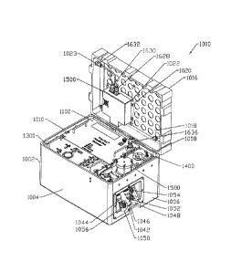
Referring to Figures 2-5, an illustrated
example of the control module 1000 is shown. As shown in
the figures, each of the sub-modules, including the
pneumatics module 1100, the hydraulics module 1300, the
fluid reservoir module 1400, the compliance module 1500,
and the electronics module 1600, are stored within a
control module chamber chassis 1002. The control module
chamber chassis 1002 contains a plurality of walls 1004,
1006, 1008, 1010 and a bottom wall 1012 to form an
interior 1014 portion, see Figure 5. The interior
portion 1014 is sized and shaped to accommodate each of
the plurality of sub-modules enclosed within. A top
portion, illustrated herein as a cover 1016, is sized and
shaped to engage the lower portion 1012. In a preferred
embodiment although non-limiting embodiment, the control
module chamber chassis cover 1016 is hingedly connected
to the bottom portion 1012 through one or more hinges,
not illustrated. Accordingly,
alternative means of
connection as known to one of skill in the art can be
used.
Enclosing the sub-modules in a removable case
allows the user the ability to move the control module
1000 and its components easily. Alternatively, each of
the sub-modules may be stored individually on a support
12
CA 02863534 2014-07-31
WO 2013/116519
PCT/US2013/024144
structure, such as a board. Secured to the inner surface
1018 of the cover 1016 through fastening members, such as
but not limited to screws 1020 and pins 1022, is the
electronics module 1500. The cover 1016 may contain at
least one opening 1023 adapted to fit a connecting device
for connecting an external device to the electronics
module 1600. Although not
illustrated, the cover 1016
and one or all of the walls may contain a locking
mechanism for securable engagement.
The interior portion 1014 preferably contains
one or more horizontal fastening beams arranged along the
interior surface of the side walls, such as a first
fastening beam 1024 secured to the interior surface 1026
of the side wall 1010. A second fastening beam 1028 is
positioned between two side walls and secures to the
interior surface 1030 (not shown) of side wall 1004 and
the interior surface 1032 of side wall 1008. The
fastening beams 1024 and 1028 may contain notches 1030
and/or apertures 1032 adapted to receive fastening
members, such as screws or tightening pins to allow each
of the sub-modules to be securely placed within. At the
top surface 1034 of the bottom wall 1012 is a bumper
1036. The side
walls 1004, 1006, 1008, or 1010 may also
contain vertically aligned beams 1038 and 1040 for added
support or securing the modules within. Additionally,
side wall 1008 may contain a recessed portion 1042
containing inlet/outlet conduits 1044 (fluid out to the
anatomical module, representing venous input) and 1046
(fluid into the control module, representing the arterial
output). Additional
recessed portions 1048 and 1050
contain additional external pneumatic connectors 1052
(arterial pneumatics out), 1054 (ventricle pneumatics
out), and 1056 and allow for air to travel to the
anatomical module 2000.
13
CA 02863534 2014-07-31
WO 2013/116519
PCT/US2013/024144
Referring to Figures 6-16, an illustrative
example of a pneumatics module 1100 is illustrated. The
pneumatics module 1100 contains the necessary components
to provide one or more modules of the cardiovascular
simulator system 10 with compressed air. The compressed
air generated allows one or more of the components of the
cardiac simulator module 2100, which is pneumatically
connected to the pneumatics module 1100, to compress and
forcibly expel any substance, such as liquid contained
therein, out, as will be described later. Accordingly,
the pneumatics module 1100 acts to provide the cardiac
simulator module 2100 with accurate simulation of cardio
dynamic functions.
Most of the components of the pneumatics module
1100 are enclosed within a pneumatic module chassis 1102.
Referring to Figure 6, the pneumatic module chassis 1102
contains a plurality of side walls 1104, 1106, 1108 (not
illustrated), and 1110 (not illustrated) and a bottom
wall 1112 (not illustrated). Each of the
walls are
arranged to create an internal compartment which stores
the working components of the pneumatics module 1100
within. A pneumatic module chassis cover 1114 encloses
the internal compartment. A pair of
handles 1116 is
attached to the outer surface 1117 of the pneumatic
module chassis cover 1114 to allow the user to easily and
quickly remove the pneumatic module chassis 1102 from the
control module chamber chassis 1002.
Referring to Figures 7-16, a pneumatic actuator
assembly, referred to generally as 1118, housed within
the pneumatic module chassis 1102 is illustrated. The
pneumatic actuator assembly 1118 provides the necessary
pressurized pneumatic fluid flow (i.e. air or other
gases) needed to drive other parts of the
cardiovasculature simulator system 10, particularly the
14
CA 02863534 2014-07-31
WO 2013/116519
PCT/US2013/024144
cardiac simulator module 2100. The
components of the
pneumatic actuator assembly 1118 are directly or
indirectly coupled to a pneumatic actuator assembly
support structure 1120. The pneumatic actuator assembly
1118 is designed to drive air into a plurality of
locations within the cardiac simulator module. To
achieve such functionality, a motor 1122, such as a
standard DC motor is used to drive a first pulley
assembly 1123. While a standard DC motor is illustrated,
other motors such as a stepper motor can be used as well.
The motor 1122, which is supported by a first
support structure 1124, rotates a first drive pulley 1126
through rotation of a first pulley shaft 1128. The first
pulley shaft 1128 is secured to a second support
structure 1130. Rotation of the first drive pulley 1126
causes rotation of a driven pulley 1132 through movement
of a first belt 1134. The belt may
be, for example, a
standard synchronous belt with teeth 1135 (see Figure
13), such as but not limited to trapezoidal teeth or
curvilinear teeth. The driven pulley 1132 is supported
by a second pulley shaft 1136 which is coupled to
parallel arms 1138 and 1140 of a third support structure
1142. Belt aligning members 1144 and 1146 are used to
align or adjust the tension of the belt 1134.
The pneumatic actuator assembly 1118 includes a
pneumatic compliance adjustment component which functions
as a compressed air cylinder driver, illustrated herein
as a cylinder tube assembly, referred to generally as
1147 on Figure 8. The cylinder
tube assembly 1147 is
configured to provide pressurized air which is directed
to the cardiac simulator module 2100 and functions to
provide contraction of the cardiac components. The
cylinder tube assembly 1147 contains a cylinder sleeve
1148 coaxially aligned with a cylinder 1150. The back
CA 02863534 2014-07-31
W02013/116519
PCT/US2013/024144
end 1151 of the cylinder 1150 is secured to a cylinder
support structure 1152. The cylinder support structure
1152 is secured to the third support structure 1142 at
the top end 1154 through insertion into the opening 1156
within the protrusion member 1158. The cylinder support
structure 1152 is further secured to the third support
structure 1142 through insertion of aligning member 1144
through the opening 1160. The cylinder support structure
1152 secures to the pneumatic actuator assembly support
structure 1120 at the bottom end 1162. The base end 1164
of the cylinder 1150 is preferably secured within the
opening 1166 of the cylinder support structure 1152. A
belt clamp 1168 couples the belt 1134 to the cylinder
sleeve 1148 such that as the belt 1134 moves, the
cylinder sleeve 1148 moves along the cylinder 1150 as
well. The belt clamp 1168 contains two plates 1170, see
Figure 9, secured together through securing members 1172,
such as screws or nuts, to allow for passage of the belt
1134 there through.
Inside the cylinder 1150 is a rod 1174 with a
piston 1176 attached, see Figure 16. The rod is coupled
to the cylinder sleeve 1148 so that, as the cylinder
sleeve 1148 moves along the fixed cylinder 1150, the
piston 1176 moves bi-directionally through space 1177 to
generate air flow in the form of pressurized air in both
directions. For example, as the piston 1176 moves to the
right, see arrow 1179, pressurized fluid in the form of
compressed air is generated and expelled out of the
cylinder 1150 through fluid conduit 1178 (see Figure 9).
The pressurized air is directed to the atrium side (to be
described later) of the cardiac chamber 2100 through
tubing (not illustrated). As the
piston 1176 moves in
the opposite direction, see arrow 1181, a second
pressurized air is generated and can be expelled out
16
CA 02863534 2014-07-31
WO 2013/116519
PCT/US2013/024144
through a different air conduit 1180 (see Figure 9). The
pressurized air through fluid conduit 1180 is directed to
the ventricle side (to be described later) of the cardiac
chamber 2100 through tubing (not illustrated). Prior to
exiting to the cardiac chamber 2100 through the fluid
conduit 1178, pressurized air exits out the cylinder
though tubing connector 1183 to a connector 1185. Prior
to exiting to the cardiac chamber 2100 through connectors
1180, pressurized air exits out the cylinder though
tubing connector 1187 to a connector 1389. Bi-
directional movement, therefore, allows the generation of
pressurized air which can be directed to various parts of
the cardiac simulator module 2100, thereby simulating
atrial and ventricular "beating" through the contraction
of corresponding cardiac simulator module portions,
thereby simulating the systolic compression of the
cardiac chambers.
The cylinder sleeve 1148 is coupled to the rod
1174 at one end 1182 through a plate 1184. The plate
1184 is secured to the cylinder sleeve 1148 through
fastening members 1183, see Figure 11. At the opposite
end 1191 of the cylinder sleeve 1148 is a bushing 1188.
The co-axial alignment allows the cylinder sleeve 1148 to
move along the cylinder in a bi-directional, i.e.
forward/reverse linear manner. The cylinder sleeve 1148
may contain one or more slots 1186 to allow for movement
without contacting other components, such as the pulley
1126 or fluid connector devices, such as elbow connectors
and/or tube barbs that are used to fluidly connect the
cylinder assembly to other components of the system.
The cylinder tube assembly 1147 further
contains a second pulley system, refereed to generally as
1192, coupleable to the cylinder sleeve 1148. The second
pulley system 1192 provides for control and manipulation
17
CA 02863534 2014-07-31
WO 2013/116519
PCT/US2013/024144
of the pneumatic actuator assembly 1123 stroke
adjustment. This system
controls the air volume,
increasing or decreasing the heart chamber compression
and thus the cardiac output, i.e. the amount of fluid
expelled from the cardiac simulator module and the force
of expelling the fluid into the cardiac simulation module
2100. The second
pulley system 1192 is supported by a
second pulley support structure 1194. An
interposer
bracket 1196 is used to provide a mechanism to trigger
changes in the stroke of the pneumatic actuator assembly
1123 through the use of a first sensing plate (limit set
point) 1198 and a second home sensing plate 1200. Both
the first sensing plates (limit set point) 1198 and the
second home sensing plate 1200 are adapted so that
interposer bracket 1196 can move through a portion there
through. Each of the sensing plates 1198 and 1200 may
contain a cut out portion 1201 and 1202 in which the
interposer bracket 1196 moves through as the cylinder
sleeve 1150 moves hi-directionally. Both sensing plates
1198 and 1200 each contain a sensor (not illustrated),
such as a laser, configured to detect directional
movement of the interposer bracket 1196.
As the cylinder sleeve 1148 moves, the
attachment interposer bracket 1196 moves through a
portion of the first sensing plate (limit set point) 1198
triggering the sensor. The first sensing plate sensor is
electronically coupled to the electronic control module
1600. The triggering event, the sensing of the interposer
bracket 1196, electrically communicates with the motor
1122 to reverse the polarity and drive the motor in the
opposite direction. Such action results in the belt 1134
reversing direction, causing the cylindrical sleeve 1150
to reverse directions as well. The
interposer bracket
1196 moves in the opposite direction towards second home
18
CA 02863534 2014-07-31
WO 2013/116519
PCT/US2013/024144
sensing plate 1200, triggering its sensor upon reaching
its destination. Once the
interposer bracket 1196
triggers the second sensor, which is electronically
coupled to the electronic control module 1600 the motor
1122 reverses direction, causing the cylinder sleeve 1148
and the interposer bracket 1196 to move in the opposite
direction, or back to the original direction of movement.
As the cylinder sleeve 1148 is moving bi-directionally,
the attached rod moves the piston 1176 as well, causing
air to move out of the cylinder 1150 and into fluid
outlets 1178 or 1180 depending on the movement of the
piston 1176.
In this manner, the interposer bracket 1196
oscillates in a back and forth motion triggering changes
in pneumatic events, i.e. expelling air into the atrium
module or ventricle module, and vice versa on the
movement in the opposite direction. The distance between
the first sensing plate (limit set point) 1198 and the
second home sensing plate 1200 is adjustable, thereby
changing the rate at which the cylinder moves in each
direction. Preferably,
first sensing plate 1198 is
adjustable with the second home sensing plate 1200 as it
is fixed to the rail 1203. A pneumatic
compression
adjustment knob 1204, see Figure 6, adjusts the
positioning of the first sensing plate 1198 relative
second sensing plate 1200. Moving the sensors provides a
mechanism to increase/decrease contractions of the atrium
and ventricle. Engaging the
pneumatic compression
adjustment knob 1204 causes the shaft 1205 to rotate the
drive pulley 1206 of the second pulley assembly 1192,
moving the second pulley assembly belt 1208 and the
driven pulley 1209. The first
sensing plate 1198 is
secured to the second pulley assembly belt 1208 thereby
moving the first sensing plate 1198 directionally along
19
CA 02863534 2014-07-31
MICO2013/116519
PCT/US2013/024144
the rail 1203. Alternative
mechanisms for controlling
the bi-directional movement of the cylinder sleeve,
including devices using feedback mechanisms such as
servomechanism, can be used.
Pneumatically coupled to the cylinder tube
assembly 1147 are manifolds 1214 and 1216 and 24V
solenoid valves 1218 and 1220. The
manifolds 1214 and
1216 and 24V solenoid valves 1218 and 1220 are supported
by support structure 1219 which is securable to the
pneumatic actuator assembly support structure 1120. The
solenoid valves 1218 and 1220 are configured to
controllably open and close to provide a mechanism to
allow air to enter into the cylinder 1150 through
solenoid air-in connectors 1221A and 1221D. As the
piston 1176 is moving in the direction of arrow 1179 in
Figure 16, one of the solenoids, for example 1218, is
open to allow air into the space 1225 within cylinder
1150. The other
solenoid, 1220, is in the closed
position so that air cannot be directed into the second
space 1227. The air within
the second space 1227 gets
compressed as the piston 1176 moves in the opposite
direction, see arrow 1181. During this movement, the
solenoid 1218 opens to allow air into space 1225 and the
solenoid 1220 is closed. A pressure
regulator 1222,
fluidly connected to the manifold 1214, prevents over
pressure of the atrial actuation system.
Figures 17-22 show an illustrative example of
the hydraulic module 1300. The hydraulic module 1300 is
adapted to: 1) provide a mechanism for removal of air
bubbles trapped within the fluid moving through the
system, 2) provide fluid pressure (simulating blood
pressure) control by controlling resistance to fluid flow
that circulates into (simulating the arterial circuit)
and out of the hydraulic module 1300, and enters back
CA 02863534 2014-07-31
WO 2013/116519
PCT/US2013/024144
into (simulating the pulmonary circuit of) the anatomical
module 2000 and 3) provide a mechanism to initiate fluid
flow through the system. Adjustment
of the fluid
pressure control is accomplished through adjusting
capillary resistance, to be described later, and through
vascular tonometry through the use of a compliance
chamber module 1500, as described later.
Similar to the other modules, most of the
components of the hydraulics module 1300 are enclosed
within a hydraulic module chassis 1302. Referring to
Figures 17 and 18, the hydraulic module chassis 1302
contains a plurality of side walls 1304, 1306, 1308, 1310
and a bottom wall 1312. The side wall 1306 contains a
. recessed portion 1314 having one or more fluid conduits
or connectors attached thereto for connecting to external
devices, such as tubes or other fluid connectors. The
recessed portion 1314 contains flanged portions 1316A,
1316B, 1316C, and 1316D which secure to a portion of the
side wall 1306 through fastening members such as screws
1318 or pins 1320. As illustrated, one or more of the
side walls may be removeably attached to one or more of
the other side walls. A top panel 1319 is secured to the
side walls 1304, 1306, 1308 and 1310 through insertion of
the pin 1320, screws 1322 and washers 1324 into openings
1325, 1326 respectively, thereby forming an interior
portion 1328.
Fluids, such as liquids simulating blood,
circulate through the system 10 through both the
anatomical module 2000 as well as though the hydraulic
module 1300. The fluid
hydraulics circuit of the
anatomical module 2000 and hydraulics module 1600 is made
up of the anatomical vasculature module 2200 (Figure 31)
as well as an interconnected loop that passes from the
arterial manifold 2224 (Figure 31) through the control
21
CA 02863534 2014-07-31
WO 2013/116519
PCT/US2013/024144
module 1000 and hydraulics module 1300 and returns to the
anatomical module 2000 through the pulmonary manifold
2236. The liquid fluid flow through the system 10 can be
outlined as follows. Fluid
passing from the arterial
manifold 2224 is hydraulically connected to a quick
disconnect fluid connector 1044 on the recessed panel
1042 (Figure 3). Fluid passes from the quick disconnect
fluid connector 1044 into a control module fluid in entry
manifold 1329, see Figure 4. The control module fluid in
entry manifold 1329 contains 2 exit ports on the arterial
side, not shown. One of these ports is connected though
a butterfly valve to the compliance chamber 1500. The
other connection allows flow to the hydraulics module
1300 through a quick disconnect fluid connector 1330
(Figure 18). Connection of
tubing to the quick
disconnect fluid connector 1330 allows fluid to enter the
hydraulics module entry manifold 1332.
Fluid flows from the port 1334 of the
hydraulics module entry manifold 1332 through the bubble
trap 1336. An illustrative
example of the bubble trap
1336 may contain an entry tube and exit port in which the
entry tube is higher than the exit port in order to cause
air to propagate to an air venting valve. The entry tube
and exit port of the bubble trap are contained within a
chamber larger in volume than normal system piping in
order to reduce flow velocity. Any air trapped in the
liquid is separated out and back into a non-contiguous
section of the hydraulics module entry manifold 1332
through the port 1338. Fluid flow then continues to the
hydraulics loop manifold 1340 via a clear PVC pipe 1342
where it then continues out port 1346 to the capillary
restriction valve 1348. The capillary restriction valve
1348 provides a means of adjusting flow conditions to the
anatomical module 2000 through, for example, the arterial
22
CA 02863534 2014-07-31
WO 2013/116519
PCT/US2013/024144
simulated and pulmonary simulated circuits. The
capillary restriction valve 1348 provides the system the
capability to replicate capillary resistance found
normally in the human body. Adjustment
of the
restriction valve 1348 simulates the resistance normally
provided by the capillary and arterial system of a human.
Use of the capillary restriction valve 1348 works in
conjunction with vascular compliance, simulated through
compliance chamber 1500, determines the resistance
associated with the cardiac module 2100, i.e. resistance
the heart pumps, and consequentially the representation
of the systolic and diastolic blood pressure.
Manipulation of the flow rate through the capillary
restriction valve 1348 by adjustment knob 1349 renders
various flow conditions found in a live cardiac system.
From the capillary restriction valve, flow passes to the
hydraulics module exit manifold 1344 where fluid exits
the hydraulics module through quick disconnect port 1356.
Fluid flows from the quick disconnect port 1356 to the
control module fluid in entry manifold 1329 where it
exits through port 1046, see Figure 3, as it returns to
the anatomical module 2000 at the pulmonary manifold
2236, see Figure 31.
The hydraulics module 1300 provides fill
function for the anatomical and hydraulics flow circuit
through a fluid connection 1358 to an in-line squeeze
bulb pump 1359 (see Figure 4) connecting to fluid
reservoir 1400. The squeeze bulb pump 1359 is actuated
by hand to draw fluid from the fluid reservoir module
1400 to the hydraulics module 1300. Alternatively, the
fluid can be drawn into the hydraulics module 1300
through other means such as an electrical pump. Fluid
entering the hydraulics module 1300 through the
aforementioned fluid connector 1358 is connected to a
23
CA 02863534 2014-07-31
W02013/116519
PCT/US2013/024144
three way ball valve 1360 and labeled as "1" "system
fill", having a side port A, 1360A, a side port B, 1360B,
and a center diverting port 1360C. The ball valve 1360
can be actuated to make connections from side port 1360A
to diverting center port 1360C, to a closed position with
no connecting ports, and to connecting side port 1360B to
diverting port 1360C through control knob 1362. Fluid
from the 1358 connector enters the 3 way ball valve
through 1360A side port and exits though center diverting
port 1360C if the valve 1360 is actuated to this
connection. Fluid flows
from valve port 1360C to the
hydraulics module exit manifold 1344. During the initial
fill cycle, the capillary resistance valve 1348 is
actuated to a closed position so that fluid being pumped
into the hydraulics circuit from the squeeze bulb pump
1359 must propagate through the entire flow circuit
before reaching de-bubbler 1336 and system rapid de-air
vent 1364, see Figure 18. The system rapid de-air vent
1364 is located on the loop manifold 1340 port 1366 and
provides venting functions for initial fill only. When
fluid reaches a poppet float valve (not illustrated)
enclosed within, the vent closes for the duration of
pressurized system use. When a fill and a de-air cycle
are complete, or the system fill bulb is not in use, the
system fill ball valve 1360 is actuated to the closed
position to maintain fluid pressure.
After the initial fluid fill, the capillary
resistance valve 1348 is opened and tubing representing
the arterial supply line (the supply line for moving
fluid away from the cardiac simulator module 2100) is
disconnected. The cardiac simulator module 2100 is used
to pump fluid through the anatomical module 2000 which
can be directed to make fluid connections from the
highest point on the anatomical circuit, such as to an
24
CA 02863534 2014-07-31
WO 2013/116519
PCT/US2013/024144
accessory organ/system module 2300, such as tubing which
represents a point located on a Circle of Willis output
if a head is used as the accessory organ/system module
2300, to a quick disconnect coupling 1056, see Figure 3.
The fluid is then directed to the hydraulics module 1300
though a quick disconnect fluid connector 1367, see
Figure 18. Fluid entering through the quick disconnect
fluid connector 1367 is hydraulically coupled to a ball
valve illustrated herein as 1372 (Figure 21) and labeled
as "3" "Model De-Air" on Figure 22. The three way ball
valve 1372 has a side port A, 1372A, a side port B,
1372B, and a center diverting port 1372C. The ball valve
1372 can be actuated to make connections from side port
1372A to diverting center port 1372C, to a closed
position with no connecting ports, and to connecting side
port 1372B to diverting port 1372C. Fluid enters
the
ball valve 1372 through port 1372C, and in use as model
de-air, functioning is connected to port 1372A when the
valve 1372 is actuated to this position. Fluid
containing air bubbles from the anatomical vascular model
enters the hydraulics module entry manifold 1332 through
a side port 1364 (Figure 18). Bubbles and fluid entering
from side port 1374 on the hydraulics entry manifold 1332
pass through the de-bubbler 1336 where the air is
separated and vented. The model de-
air 1372 three way
ball valve can also be used to propagate additional flow
through the vasculature module 2200, simulated as neuro-
vessel vasculature, by selecting the 1372B port on the
valve 1372 using knob 1376. The knob
1376 is
hydraulically coupled to a side port on the hydraulics
exit manifold 1344. Such action can be used to set an
appropriate amount of flow on the capillary resistance
valve 1348.
CA 02863534 2014-07-31
WO 2013/116519
PCT/US2013/024144
The hydraulics system de-air circuit consists
of the rapid de-air vent, a system pressure relief 1375,
and the de-bubbler unit 1336. These units expel air and
fluid to a common vent line (not illustrated) which is
hydraulically coupled to a 3 way ball valve (not
illustrated but represented generally by 1377 and labeled
by the "2" "System De-Air" on Figure 22.) The three way
ball valve represent by 1377 has a side port A, a side
port B, and a center diverting port C. The three
way
ball valve represent by 1377 can be actuated, through
knob 1378 to make connections from its side port A to the
diverting center port C to a closed position with no
connecting ports, and to connecting side port B to
diverting center port C. The common
vent line is
hydraulically coupled to the side port A of the 1377 ball
valve. If the valve
is actuated to connect A and C
ports, then air or fluid will flow through the valve
represent by 1377 to the fluid connector 1358 on recessed
panel 1314, see Figure 18. Fluid
passing through the
connector 1358 is vented to a port on the reservoir
module 1400. The system
De-Air valve 1377 can also be
closed for system pressure retention.
The hydraulics module can be drained for
transport or maintenance by actuating the system fill and
system de-air ball valves 1360 and 1377 to the drain
position by actuating both valves to their B port. A
drain connection is made to a tube 1380 (Figure 20) which
connects to loop manifold 1340. As the hydraulics module
and connected circuits are drained, air is drawn in
through drain vent 1382, (Figure 18) and displaces water
draining out of drain tube 1380. The hydraulics module
1300 may contain a gauge 1384 fluidly connected to the
hydraulics entry manifold 1332 through connector 1386.
The gauge 1384 may also be fluidly connected to the
26
CA 02863534 2014-07-31
WO 2013/116519
PCT/US2013/024144
pressure relief valve 1375 through connector 1388. The
gauge 1384 therefore can be used to measure the incoming
fluid pressure, represented as the arterial input before
reaching the capillary valve 1348. Excess pressure can
be released to the fluid reservoir module 1400 so that
the desired fluid pressure, such as 0-200mm/Hg, can be
achieved.
Referring to Figures 2, 4, and 23, the control
module 1000 further contains a fluid reservoir module
1400. The fluid reservoir module 1400 contains a fluid
storage chamber 1402 adapted to hold a fluid, and may
contain a check valve to control back flow of fluid. The
fluid can be any liquid that simulates blood. In a
preferred embodiment, the fluid is a clear blood analog
having properties which duplicate the viscosity of human
blood and mimics the friction coefficients as
endovascular devices, wires, and catheters traverse the
vasculature system.
Alternatively, the fluid can be
whole blood. Accordingly,
any fluid can be used and
modified to have the viscosity and/or flow rate that is
the same as or approximates that of blood flow through
veins or arteries. The fluid
could be clear, or may
include a dye so that the fluid flow can be visualized
throughout the system. In any form,
the fluid storage
chamber 1402 contains a plurality of side walls, 1404,
1406, 1408, and 1410, and a bottom wall 1412 (not
illustrated). A top cover
1414 provides an enclosed
interior portion 1416 (not illustrated) for storage of
the fluid. The top
portion contains a ridge 1418
extending around the perimeter which is used to attach tp
the top end of the side wall 1006 of the control module
chamber chassis at one end and to fastening beam 1028.
27
CA 02863534 2014-07-31
WO 2013/116519
PCT/US2013/024144
The top cover 1414 may contain indictors, such as a gauge
1420. A window may
be utilized to provide visual
confirmation of flow level.
A fluid connector 1422 may be used to fill
and/or remove the liquid. The bottom
section of side
wall 1404 may contain openings 1424 and 1426 to provide
for fluid connectors to other components of the system
for fluid connection into the fluid storage chamber 1402,
or for attachment to a water drain system. Handles 1428
and 1430 attach to the fluid storage chamber 1402 to
provide easy removal from and placement into the control
module 1002. As described
previously, to start the
fluid flow, the fluid storage chamber 1402 is fluidly
connected to a pump, illustrated herein as a hand pump
1359, see Figure 4. Engaging the
hand pump 1359 (see
Figure 4) through squeezing or compression causes fluid
to flow from fluid storage chamber 1402 into the
hydraulics module 1300. Electrical
pumps connected to
the electrical module or other mechanisms which can
activate flow of the fluid can be used.
Referring to Figures 24-28, an illustrative
example of a compliance chamber module 1500 is shown.
The compliance chamber module 1500 acts as a system fluid
storage device and is adapted to functionally provide
compensation for the fact that the entire vasculature
system is not modeled. Accordingly,
the compliance
chamber provides an anatomically correct range of cardiac
system compliance and compensation given that the system
10 does not replicate all vasculature vessels contained
within the entire human cardiovasculature system. For
example, vasculature to the lower extremities,
particularly the legs, is generally not included as part
of the vasculature module 2200. To replicate
accurate
cardio dynamics with anatomically accurate cardiac
28
CA 02863534 2014-07-31
WO 2013/116519
PCT/US2013/024144
physiology while pumping into an incomplete modeled
vascular system, the compliance chamber is used. The
compliance chamber simulates the vascular volume and
tonometry of the non-molded parts of the system. The
vascular tonometry simulates arterial tension and can be
changed by adding or removing air from the compliance
chamber 1500. Depending on
the amount of air, the
conditions of hypertension or hypotension can be
simulated.
Preferably, the compliance chamber module 1500
is placed within the system in which fluid flow is
returning from the vasculature simulator module 2200 on
its way toward the hydraulics module 1300, and can be
fluidly attached to the control module fluid in entry
manifold 1329. Fluid enters into the compliance chamber
module 1500 and can be controllably replaced back into
the system. The compliance chamber module 1500 contains
a top cover plate 1502, a bottom plate 1504, and a main
body 1506 there between. The main
body may be
constructed of a clear plastic material to allow for
visualization of the contents therein. Several
chamber
stud posts 1508, attached to the top cover plate 1502
through a washer 1510 and wing nut 1512, secure the top
cover plate 1502 to the bottom plate 1504. The chamber
stud posts 1508 may contain a swivel nut or threaded nut
1514 at one end to secure to the bottom cover. The main
body contains a screen 1516 and diaphragm 1518 positioned
at the bottom plate 1504. The
diaphragm separates the
main body 1506 into a top portion and a bottom portion,
and is made of a material that prevents liquid or gas
fluids from diffusing or crossing through.
Fluid, such as the fluid circulating through
the anatomical module 2000 and representing blood flow,
enters into the main body 1506 through a first fluid
29
CA 02863534 2014-07-31
WO 2013/116519
PCT/US2013/024144
inlet/outlet 1520. A gas can be inserted into the space
above the diaphragm 1508 through a second fluid
inlet/outlet 1522 and provides back pressure acting
against the diaphragm 1518. Additional air or gas placed
into the main body 1506 increases the back pressure while
removal of the gas decreases the back pressure. Based on
the amount of gas in the compliance chamber, the flow of
liquid out of the chamber is controllably released back
into the system 10. A third fluid inlet/outlet 1524 may
be used to bleed out any excessive pressure built up if
needed. 0-rings 1526 and 1528 are sealed against the top
cover plate 1502 and the bottom plate 1504 respectively.
The compliance chamber module 1500 rests on a compliance
chamber module mount 1530 and secures to the control
module chamber chassis 1002 through fastening devices,
such as screws 1532 and set screws 1534. The use of the
diaphragm 1518 is illustrative only and may be replaced
with other accumulators that use pistons, springs, or
bladders as known in the art.
Referring to Figures 30A and 30B, an
illustrative embodiment of the electronic control module
1600 is shown. The electronics module 1600 contains the
main controlling aspects of the system 10, including a
plurality of logic chips that allow the system to
function and/or to be modified based on the task to be
undertaken. In the
illustrated example, the electronic
control module 1600 is located on the inner surface 1018
of the control module chamber chassis cover 1016 and has
the main function of providing the power and circuitry
for driving the interactions between the modules.
Several of the components are secured to the
control module chamber chassis cover 1016 and enclosed by
an electronics module cover 1602.
Alternatively, the
components may be housed in a removable electronics
CA 02863534 2014-07-31
WO 2013/116519
PCT/US2013/024144
module chassis. A main power supply, illustrated herein
as a 24V DC regulated AC to DC converter 1604, provides
power to the system 10 and is electrically coupled to an
electronic controller circuit board 1606 at power
connection 1608 through cable 1610. Alternatively,
the
main power supply could be an external 24V DC battery.
The electronic controller circuit board 1606 contains
individual logic circuitry for various components of the
system 10. Each of the circuitry is connected at various
connection points, including the pneumatic module motor
logic connector 1612, the first and second sensors logic
connectors 1614 (home sensor) and 1618 (limit sensor),
the atrium solenoid logic connector 1620, the ventricle
solenoid logic connector 1622, the handheld device logic
connector 1621, and a fan logic connector 1623, are
electrically coupled to the motor 1122, first and second
sensors 1210 and 1212, the atrium solenoid 1216, the
ventricle solenoid 1214, a fan 1625 (to cool down the
control system), or an 24V DC accessory 1627.
Additionally, the main power supply 1604 may also be
coupled to a power entry 1629. Electrical coupling can
be accomplished by means known to one of skill in the
art, and may include, for example the use of a series of
cables 1624 and electrical wiring 1626 which connect
through the use of electrical connectors such as 1628,
1630 1632, 1634, 1636, and 1638. Each of the connectors
may contain electrical pins 1640, electrical sockets
1642, or male/male feed thru devices 1644. Additionally,
brackets 1646 may be used to support one or more of the
connectors.
A handheld device 1648 is electrically coupled
to the electronics module 1600 through the circuit logic
connector 1621 to allow the user the ability to control
the functioning of the system and manipulate one or more
31
CA 02863534 2014-07-31
WO 2013/116519
PCT/US2013/024144
of the modules. Any of the
control mechanisms or
operational parameter adjustments discussed throughout
the application can be controlled using the handheld unit
1648. Referring to Figure 30C, an illustrative example
of the handheld device 1648 is shown. The handheld
device 1648 is constructed to provide a mixture of
command functions and visual indicators. For example, a
cardiac rate control knob 1650 can be manipulated by the
user to control the cardiac module 2100, thereby
affecting the heart rate (beats per minute) simulation.
A run-stop switch 1652 acts to pause one or more aspects
of the system, preferably the beating of the heart, while
allowing other aspects of the system to function.
Several indicator LEDs are used to indicate function of
one or more aspects of the system, including, but not
limited to, the power 1654, the atrium assembly 1656, the
ventricle assembly 1658, and the system run 1660.
The control module 1000 interacts with the
anatomical module 2000 by delivering pressurized air flow
and liquids to the cardiac simulator module 2100. The
action of the pressurized air allows the cardiac
simulator module 2100 to function like a heart muscle of
an individual or animal by contracting and expanding,
forcing fluid representing blood flow to travel within
the vasculature simulator module 2300. The control
module is designed to supply pulses of pressurized air to
the cardiac module 2100. Fluid
pressures and fluid
dynamics/flows are created by the pumping action of the
cardiac module itself. Figures 31-
40 illustrate the
components of the cardiac simulator module 2100, as well
as the vasculature module 2200. The Figures additionally
illustrate the attachment of an embodiment of the
accessory organ/system module 2300, illustrated herein as
a head.
32
CA 02863534 2014-07-31
WO 2013/116519
PCT/US2013/024144
The cardiac simulator module 2100 is secured to
a support board 2102 through a cardiac simulator module
support structure 2104 through fastening members, such as
screws 2106. The cardiac simulator module 2100 comprises
several chambers representing the left side of the heart,
and includes an atrial actuator, illustrated herein as a
left atrium assembly 2108, and a ventricle actuator,
illustrated herein as a left ventricle assembly 2110.
The atrium and the ventricle may be molded using a
standard size and shape. Preferably, the
present
invention uses an atrium and a ventricle that have been
molded using Computer Tomography (CT Scan) imagery of a
heart as well as its vasculature. The atrium
and
ventricle can be molded to represent the exact size and
shape analogous to that of individual patients.
The left atrium assembly 2108 pneumatically
connects to the fluid connector 1178 through tubing, not
illustrated. Pressurized
air enters the left atrium
assembly 2108 through the atrium pneumatic-in connector
2111 which is coupled to an elbow connection 2112 to tube
barb 2114 for fitting to a tube. The left
atrium
assembly 2108 contains an outer air pneumatic support
structure 2116 which is preferably fabricated from a
hard, firm, clear cast plastic, such as urethane. Inside
of the outer air pneumatic support structure 2116 is a
flexible bellow assembly 2120, see Figure 36, which is
pneumatically connected to elbow connection 2112 to tube
barb 2114. Pneumatic
pressure generated from the
pneumatic modules and pneumatically connected to the
atrium pneumatic-in connector 2111 inflates the bellows.
Additional injection ports may be included to provide a
mechanism to inject dyes or representative medicine into
various places within the system 10. As the
bellow
assembly 2120 expands it compresses a left atrium chamber
33
CA 02863534 2014-07-31
WO 2013/116519
PCT/US2013/024144
2122. The bottom ends 2124 and 2126 of the atrium outer
air pneumatic support structure 2116 connect to plates
2228 and 2230, see Figure 38.
The left atrium chamber 2122 is preferably made
of a soft, flexible, clear silicone which is capable of
contracting and expanding. To allow fluid flow into the
left ventricle at the appropriate time, i.e. when the
left atrium contracts, without fluid flowing back into
the left atrium upon relaxation, the left atrium 2128
contains a one way valve, illustrated herein as a
synthetic valve 2129, see Figure 36. The valve
2129
represents a mitral valve, and as an illustrative example
could be a synthetic replication.
Alternatively, the
valve may be a transplant of an actual mammalian mitral
valve, such as a swine, or a human mitral valve.
The left ventricle module 2110 is composed of a
left ventricle pneumatic chamber 2130 which surrounds the
left ventricle chamber 2132, see Figures 34, 36, and 38.
The left ventricle pneumatic chamber 2130 is preferably
fabricated from a hard, firm, clear cast plastic, such as
urethane. The left ventricle chamber 2132 is preferably
made of a soft, flexible clear plastic, such as silicone.
A first end 2134 of the left ventricle pneumatic chamber
2130 contains a flange 2136 for connection to the left
atrium assembly 2108, preferably to a cardiac support
structure 2137. The second
end 2138 of the left
ventricle pneumatic chamber 2130 contains a second flange
2140. The second
flange 2140 connects to a ring 2141
sized and shaped to encircle an apex 2142 of the left
ventricle chamber 2132. In this
embodiment, apex 2142
does not contract with the rest of the left ventricle
chamber 2132. In an
alternative embodiment, the apex
2142 is fully enclosed by the left ventricle pneumatic
chamber 2130, see Figure 40.
34
CA 02863534 2014-07-31
WO 2013/116519
PCT/US2013/024144
As illustrated in Figure 39, the left ventricle
chamber 2132 does not include any vasculature. In an
alternative embodiment, the left ventricle chamber 2132
includes anatomically correct vasculature 2144, such as
the left coronary artery, the left circumflex artery, the
left marginal artery, the left anterior descending
artery, and the diagonal branch, of the left ventricle
chamber 2132. The
vasculature can be "normal"
vasculature, or can be that of disease state vasculature.
In addition, the normal or the disease state vasculature
can be adapted to represent the exact vasculature of
individual patients (through use of CT scans, MR and/or
rotational angiography) or can be designed to represent
normal/disease states of non-patient specifically.
Moreover, sections of the ventricle chamber 2132 may
include thick sections 2146 (simulating ventricular
hypertrophy) and/or thinner sections 2148 (simulating
ventricular hypotrophy) to simulate differing resistance
of the heart to contraction and expansion, see Figure 40.
While not illustrated, such features may apply to the
atrium 2122 as well. The left ventricle module 2110 is
fluidly connected to one or more parts of the vasculature
module 2200 through various connectors. For example,
fluid flows out of the left ventricle into the
vasculature module 2200 through a valve, illustrated
herein as a synthetic aortic valve 2150, see Figure 35.
The synthetic aortic valve 2150 may be constructed from a
synthetic plastic or may be an animal such as a swine/pig
or human aortic valve. In either case, the valve 2150 is
designed to allow fluid flow at the proper time in one
direction, i.e. out of the left ventricle chamber and
into the vasculature module 2200.
CA 02863534 2014-07-31
WO 2013/116519
PCT/US2013/024144
The vasculature module 2200 is made of a
plurality of members, such as synthetic tubing, that
provide fluid flow into and away from the cardiac
simulator module 2100. Similar to
the atrium and
ventricle, the vasculature module 2200 tubing can be made
to replicate the size, shape, and tonometry of the
vasculature of specific patients. Preferably, the tubing
is made of clear medical grade plastics having flexural
modules, or stiffness, which corresponds to a desired
need. Referring to Figures 1, 34 and 37, fluid flows out
of the left ventricle chamber 2132 and into tubing
representing the aorta 2202 and aortic arch 2203. One or
more aorta connectors, such as but not limited to, 2204
(subclavian artery), 2206 (right common carotid artery),
and 2208 (braciocephalic artery) are used to fluidly
attach to other components of the vasculature module
2200, such as tubing representing the vertebral arteries
2210, and fluidly connect to the periphery organ/system
module 2300 (illustrated on Figure 31), the left common
carotid artery 2212 and connected to fluid connector 2310
(illustrated on Figure 31) and the right common carotid
artery 2214 connected to fluid connector 2312
(illustrated on Figure 31), see block diagram 1. Fluid
further flows into the descending aorta 2216 and connects
to the right Iliac artery 2218 and the left Iliac artery
2220. Fluid flow
out of the cardiac simulator module
2100 is directed through the tubing and eventually into
an arterial manifold 2224 through one or more arterial
manifold inlets 2226, 2228, 2230, 2231, or 2232,
depending on which part of the system the fluid is
traveling, see Figure 31. Fluid then
travels out the
arterial manifold 2224 through the output connector 2234,
through tubing (not illustrated) back to the control
module 1000.
36
CA 02863534 2014-07-31
WO 2013/116519
PCT/US2013/024144
Fluid typically enters the cardiac simulator
module 2100, and then flows into the vasculature module
2200 through a pulmonary manifold 2236. Fluid flows into
the pulmonary manifold 2236 through the pulmonary
manifold inlet 2238 and out to tubing from the pulmonary
manifold outlets 2240, 2242, 2244, and 2246. The outlets
2240-2246 connect tubing representing the two left
pulmonary veins 2248 and 2250, and two right pulmonary
veins 2252 and 2254, see block diagram Figure 1. The two
left pulmonary veins 2248 and 2250 and two right
pulmonary veins 2252 and 2254 direct flow into the left
atrium chamber 2132.
Each of the components of the vasculature
module 2200 may be supported by adjustable elevation
posts 2256 mounted to the support plate 2102 through
support plate connecting elements 2258. The
adjustable
elevation posts 2256 also contain tab elements 2260 that
are adapted to prevent interference with the natural
reactions of the anatomical elements to flow and pressure
wave transmission within the anatomical module 2000. The
posts 2256 provide 360 degree access and visualization of
the anatomical parts and/or surfaces of the
cardiovasculature system 10 for observation and
characterization. The posts
2256 can be adjustable in
the Z-axis, and can be mounted in the X and Y coordinate
movement bracket. The combined movements allow for the
augmentation of the tortuosity or offsets to the
anatomical relationships at various increments along the
contiguous anatomy model. The posts
2256 may also
provide light illumination to one or more tubing to
illuminate pathways back to the interior of the
anatomical module 2000 through the translucent or
transparent components of the anatomical module 2000.
The posts 2256 also provide for quick disconnect from one
37
CA 02863534 2014-07-31
WO 2013/116519
PCT/US2013/024144
or more parts of the anatomical module 2000 for either
replacement of one or more of the components or for
exchange with other anatomical profile preferences.
Referring to Figures 31-33 and 41, the
periphery organ/system module is shown as a head 2302.
The head 2302 contains a bottom portion 2304 connected to
a board 2305 and/or a top portion 2306 through fastening
members 2308, such as screws or nuts. Such arrangement
allows for the top portion 2306 to be removed and
replaced. The bottom portion 2304 contains one or more
fluid connectors 2310 and 2312 which are adapted to
fluidly connect the head 2302 to one or more components
of the vasculature module 2200. Such fluid
connection
allows the user to evaluate the effects of surgical
techniques or procedures with peripheral organs or
systems.
Figure 41 illustrates an illustrative example
of the head unit 2302 with a plurality of tubing, 2312
and 2314, representing the cerebrovasculature. The
cerebrovasculature is placed within a gel like material
2316 in order to mimic the compliance of the vessels in
the subarachnoid space and surrounding brain. The
vasculature system, from the carotid bifurcation to the
intracranial circulation, as well as any pathology can be
replicated. The head unit
2302 may also contain
additional tubing 2318 connectable to other parts of the
system 10, such as to connector 1054.
Referring back to Figure 1, the present
invention can be further demonstrated through an
illustrative example of the simulator system 10 cycle.
Fluid, such as a liquid representing blood flow through
the system, stored within the fluid reservoir module
1400, is passed through the manual hand pump 1359 with
integral check valve module 1432. The fluid is
passed
38
CA 02863534 2014-07-31
WO 2013/116519
PCT/US2013/024144
through the primary de-bubbler and/or the rapid debubbler
to remove any bubbles and/or gases that may have formed
therein. Removal of the bubbles prevents fluid dynamics
abnormalities which may negatively affect the precision
and accuracy of the cardio dynamics of the system,
thereby enhancing the overall system performance. Once
de-bubbling is complete, the fluid enters the anatomical
module 2000 through tubing which is fluidly connected to
the pulmonary manifold 2236. Fluid in the
pulmonary
manifold 2236 represents oxygenated blood returning from
the lungs, not used in the presently described system,
and flows into the left atrium assembly 2108 through the
two left and two right pulmonary veins.
The atrium chamber 2122 fills with fluid and
the pressure of the fluid, measured at the systolic side
of the circuit, is controlled by the control module 1000
to be in the minimal normal range for diastolic pressure
of a human heart (50-80 mm HG). The actual
blood
pressure of 120/80 (systolic/diastolic) obtained by the
system is a combination function of the fluid flow volume
(simulated by manipulation of the control module in
relationship to the cardiac simulator module), the
cardiac simulated heart rate, arterial compression,
ventricular compression (or ejection fraction, simulated
as the amount of fluid ejected out of the atrium chamber
or ventricle chamber), the capillary resistance
(simulated effects by the manipulation of the compliance
chamber) and the vascular tonometry or tension (simulated
effects by the manipulation of the compliance chamber).
While the system does not independently adjust
for systolic and diastolic values, various combinations
of these parameters affect the systolic and diastolic
numbers to varying degrees. The value of the diastolic
pressure can be manipulated to above or below the normal
39
CA 02863534 2014-07-31
WO 2013/116519
PCT/US2013/024144
ranges to simulate various disease states. Initiated by
the control module 1000, the left atrium is contracted.
The electronics module 1600 drives the motor 1122
directionally, clockwise or counter clockwise, moving the
piston 1176 bi-directionally in the cylinder 1150 in a
direction which creates pressurized air flow to be
directed into the left atrium chamber 2128. The
pressurized air generated flows through tubing and enters
the outer air pneumatic support structure 2116 of the
left atrium 2128. The air causes the atrium bellows 2126
to compress against the left atrium chamber 2122,
reducing the volume within the left atrium chamber 2122.
Reduction of the volume results in fluid being expelled
through the mitral valve 2129 and into the left ventricle
pneumatic chamber 2130.
At the proper timing, pressurized air generated
from the return stroke of the piston moving within the
cylinder is controlled by the interaction of the control
module and the second pulley system. The pressurized air
generated travels through the tubing of the vasculature
module into the left ventricle pneumatic chamber 2130.
The pressurized fluid causes a reduction of volume within
the left ventricle chamber 2132, resulting in the
expulsion of fliud through the synthetic aortic valve
2150 and into the aortic arch 2202. The pressure of the
fluid is set within the normal range of normal systolic
pressure, 100-160 mm Hg. The flow rate, 2-6L/min of flow
at 70 beats per minute of the heart and the ejection
fraction (50-65%) is set within the normal range of the
human heart. However, such conditions can be manipulated
by the electronic control module 1600 to change the
corresponding pressure, volume flow rate, ejection
fraction, or combinations thereof. The fluid
ejected
from the left ventricle chamber is under pressure and
6
flows through various portions of the ventricle module,
such as the vertebral arteries, the left common carotid
artery, and the right common carotid artery. Fluid also
flows down to the descending aorta and into the right
iliac artery and the left iliac artery. Eventually all
fluid is directed to the arterial manifold 2224 and
directed back to the control module 1000 in which the
flow rate is adjusted, and air bubbles are removed.
Vascular tension can be simulated and adjusted through
several mechanisms, such as through the combination of
the capillary resistance setting, the compliance chamber
back pressure adjustments, and through the molded
vasculature simulator module representing the arteries
having various durometer values. Fluid is then
returned
to the pulmonary manifold to start a new cycle.
As described previously, abnormal heart
conditions can be simulated by varying the force,
duration, and freguendy of the air burst generated by the
atrium/ventricle air cylinder through commands sent from
the control and adjustments within the fluid control
system.
It is to be understood that while a certain
form of the invention is illustrated, it is not to be
limited to the specific form or arrangement herein
described and shown. It will be
apparent to those
skilled in the art that various changes may be made
without departing from the scope of the invention and the
41
CA 2863534 2017-10-17
CA 02863534 2014-07-31
W02013/116519
PCT/US2013/024144
invention is not to be considered limited to what is
shown and described in the specification and any
drawings/figures included herein.
One skilled in the art will readily appreciate
that the present invention is well adapted to carry out
the objectives and obtain the ends and advantages
mentioned, as well as those inherent therein. The
embodiments, methods, procedures and techniques described
herein are presently representative of the preferred
embodiments, are intended to be exemplary and are not
intended as limitations on the scope. Changes therein and
other uses will occur to those skilled in the art which
are encompassed within the spirit of the invention and
are defined by the scope of the appended claims.
Although the invention has been described in connection
with specific preferred embodiments, it should be
understood that the invention as claimed should not be
unduly limited to such specific embodiments. Indeed,
various modifications of the described modes for carrying
out the invention which are obvious to those skilled in
the art are intended to be within the scope of the
following claims.
42