Note: Descriptions are shown in the official language in which they were submitted.
CA 02864524 2014-08-13
WO 2013/122971 PCT/US2013/025806
1
SYSTEMS AND METHODS FOR COMPUTING SURFACE OF FRACTURE PER
VOLUME OF ROCK
FIELD
The present disclosure relates to drilling wellbores in subterranean
formations. The
present disclosure also relates to systems and methods for analyzing borehole
productivity.
BACKGROUND
Oil prices continue to rise in part because the demand for oil continues to
grow, while
stable sources of oil are becoming scarcer. Oil companies continue to develop
new tools for
generating data from boreholes with the hope of leveraging such data by
converting it into
meaningful information that may lead to improved production, reduced costs,
and/or
streamlined operations.
Borehole imagery is a major component of the wireline business (for example,
Schlumberger's FMI', Formation MicroScanner, OBMI'm Tools), and an increasing
part of
the logging while drilling business (for example, Schlumberger's GeoVision',
RAB
Resistivity-at-the-Bit, ARCS Array Resistivity Compensated tools). While
borehole imagery
provides measurements containing abundant data about the subsurface, it
remains a challenge
to extract the geological and petrophysical knowledge contained therein. Yet,
accurately
characterizing the natural fracture porosity of a hydrocarbon reservoir is an
essential step to
assessing its productivity index and quantity of oil therein.
SUMMARY
The present disclosure relates to methods and systems for analyzing raw data
from
borehole imagery tools, for example analyzing zonal resistivity maps generated
from
CA 02864524 2014-08-13
WO 2013/122971 PCT/US2013/025806
2
measurements of certain resistivity tools, and converting the data into
information relating to
well productivity.
In some embodiments, the methods involve estimating surface fracture per
volume of
rock from a borehole image taken in a borehole which has segments of fractures
occupying
one or more planes, wherein the estimation does not require defining the one
or more planes
bearing the segments. In some embodiments, the borehole image is in the form
of a zonal
resistivity map. In some embodiments, the method involves identifying linear
segments
corresponding to fractures from the borehole image, such as from the zonal
resistivity map,
sorting the segments into angular classes and generating a cumulated segment
length
distribution over the angular class, correlating the cumulated segment
distribution with a
theoretical segment length distribution for each of the angular classes to
obtain the length of
fracture surface of borehole contribution of each angular class, computing a
surface fracture
per volume of rock for each angular class from the length of fracture surface
of borehole for
each class, and summing together the surface fracture per volume of rock for
each angular
class to arrive at a total surface fracture per volume of rock. In further
embodiments, the
number of angular classes is nine, and each angular class spans about ten
degrees (from 0-10
to 80-90). In some embodiments, the method involves generating a borehole
image from data
collected by a downhole tool, such as a resistivity tool, and then estimating
surface of fracture
per volume of rock from the data, wherein the data is correlated to segments
of fractures and
the estimation does not require defining planes in the borehole bearing the
segments.
In some embodiments, the systems include: a downhole tool, such as a
resistivity
tool, for collecting data in a borehole from which information about segments
corresponding
to fractures in the subsurface may be derived; and, a processor including
machine-readable
instruction for estimating surface of fracture per volume of rock from the
data (directly or
CA 02864524 2014-08-13
WO 2013/122971 PCT/US2013/025806
3
indirectly), without defining the planes in the borehole bearing the segment.
In some
embodiments, the systems further include machine-readable instructions wherein
the
estimating includes reconstructing theoretical elliptical fractures from the
segment data,
calculating the length of fracture per segment per surface of borehole for
each of the
theoretical ellipses, and deriving a surface of fracture per volume of rock
from each length of
fracture segment per surface of borehole.
The identified embodiments are exemplary only and are therefore non-limiting.
The
details of one or more non-limiting embodiments of the invention are set forth
in the
accompanying drawings and the descriptions below. Other embodiments of the
invention
should be apparent to those of ordinary skill in the art after consideration
of the present
disclosure.
BRIEF DESCRIPTION OF DRAWINGS
Figure 1 is a partial schematic representation of an exemplary apparatus for
logging
while drilling that is compatible with the systems and methods of this
disclosure.
Figure 2 is a partial schematic representation of an exemplary wireline
apparatus that
is compatible with the systems and methods of this disclosure.
Figure 3 is a schematic representation of a borehole image illustrating how
images
from a cylindrical borehole are viewed in two dimensions.
Figure 4 is a schematic representation of how dipping planes are represented
by
sinusoids for non-vertical cylindrical boreholes.
Figure 5 illustrates the similar segment distributions that can result from
both
complete or partial sinusoids.
CA 02864524 2014-08-13
WO 2013/122971 PCT/US2013/025806
4
Figure 6 illustrates the relationship between the intersection of a fracture
and the well
and segment classes.
Figure 7 is a series of graphs showing the theoretical segment length vs.
angle
distribution for fracture apparent dip when sorted into nine angular classes.
Figure 8 is a zonal resistivity map and the related graph of the actual
distribution of
fracture segments in that map and their angular distribution in nine angular
classes.
Figures 9A-9D illustrate the process of deriving P2i(x4Y).
Figure 10 is a graphic of a methodology for deriving P32/P21.
DETAILED DESCRIPTION
Unless defined otherwise, all technical and scientific terms used herein have
the same
meaning as is commonly understood by one of ordinary skill in the art to which
this
disclosure belongs. In the event that there is a plurality of definitions for
a term herein, those
in this section prevail unless stated otherwise.
Where ever the phrases "for example," "such as," "including" and the like are
used
herein, the phrase "and without limitation" is understood to follow unless
explicitly stated
otherwise. Therefore, "for example a mud turbine generator" means "for example
and
without limitation a mud turbine generator."
The terms "comprising" and "including" and "involving" (and similarly
"comprises"
and "includes" and "involves") are used interchangeably and mean the same
thing.
Specifically, each of the terms is defined consistent with the common United
States patent
law definition of "comprising" and is therefore interpreted to be an open term
meaning "at
CA 02864524 2014-08-13
WO 2013/122971 PCT/US2013/025806
least the following" and also interpreted not to exclude additional features,
limitations,
aspects, etc.
The terms "about" or "substantially" are meant to account for variations due
to
experimental error, or alternatively to permit deviations from the measured
quantity or
descriptor that don't negatively impact the intended purpose. All measurements
or numbers
are implicitly understood to be modified by the word about, even if the
measurement or
number is not explicitly modified by the word about.
The terms "wellbore" and "borehole" are used interchangeably.
The phrases "bottom hole assembly" and "downhole tool" are used
interchangeably.
"Measurement While Drilling" ("MWD") can refer to devices for measuring
downhole conditions including the movement and location of the drilling
assembly
contemporaneously with the drilling of the well. "Logging While Drilling"
("LWD") can
refer to devices concentrating more on the measurement of formation
parameters. While
distinctions may exist between these terms, they are also often used
interchangeably. For
purposes of this disclosure MWD and LWD are used interchangeably and have the
same
meaning. That is, both terms are understood as related to the collection of
downhole
information generally, to include, for example, both the collection of
information relating to
the movement and position of the drilling assembly and the collection of
formation
parameters.
Whenever the phrase "derived from" or "calculated from" or the like are used,
"directly or indirectly" are understood to follow. Also, the phrases
"estimating from the
data" or "calculating from the data" are understood to mean "from the data or
subset of the
data." By way of example, a borehole image contains an abundance of data about
a borehole.
CA 02864524 2014-08-13
WO 2013/122971 PCT/US2013/025806
6
In some embodiments, "estimating surface of fracture per volume of rock" first
involves
extracting and converting a subset of data¨analyzing the data to identify
segments, further
analyzing which segments correspond to fractures, and estimating proceeds on
only the
subset of data extracted from the original set which corresponds to segments
of fractures.
When a range of angles is provided herein, such as a range of from X degrees
to Y
degrees, the range is understood to include the lower number ("X") and exclude
the upper
number ("Y"). Thus, the angular class spans the range of from about 20 degrees
to about 30
degrees means that the angular class includes 20 degrees but excludes 30
degrees.
FIGS. 1 and 2 illustrate non-limiting, exemplary well logging systems used to
obtain
well logging data and other information, which may be used to estimate surface
of fracture
per volume of rock and/or analyze borehole productivity in accordance with
embodiments of
the present disclosure.
FIG. 1 illustrates a land-based platform and derrick assembly (drilling rig)
10 and drill
string 12 with a well logging data acquisition and logging system, positioned
over a wellbore
11 for exploring a formation F. In the illustrated embodiment, the wellbore 11
is formed by
rotary drilling in a manner that is known in the art. Those of ordinary skill
in the art given
the benefit of this disclosure will appreciate, however, that the subject
matter of this
disclosure also finds application in directional drilling applications as well
as rotary drilling,
and is not limited to land-based rigs. In addition, although a logging while
drilling apparatus
is illustrated, the subject matter of this disclosure is also applicable to
wireline drilling (for
example as shown in FIG. 2).
A drill string 12 is suspended within the wellbore 11 and includes a drill bit
105 at its
lower end. The drill string 12 is rotated by a rotary table 16, energized by
means not shown,
CA 02864524 2014-08-13
WO 2013/122971 PCT/US2013/025806
7
which engages a kelly 17 at the upper end of the drill string. The drill
string 12 is suspended
from a hook 18, attached to a travelling block (also not shown), through the
kelly 17 and a
rotary swivel 19 which permits rotation of the drill string 12 relative to the
hook 18.
Drilling fluid or mud 26 is stored in a pit 27 formed at the well site. A pump
29
delivers the drilling fluid 26 to the interior of the drill string 12 via a
port in the swivel 19,
inducing the drilling fluid to flow downwardly through the drill string 12 as
indicated by the
directional arrow 8. The drilling fluid exits the drill string 12 via ports in
the drill bit 105,
and then circulates upwardly through the region between the outside of the
drill string 12 and
the wall of the wellbore, called the annulus, as indicated by the direction
arrows 9. In this
manner, the drilling fluid lubricates the drill bit 105 and carries formation
cuttings up to the
surface as it is returned to the pit 27 for recirculation.
The drill string 12 further includes a bottomhole assembly ("BHA"), generally
referred to as 100, near the drill bit 105 (for example, within several drill
collar lengths from
the drill bit). The BHA 100 includes capabilities for measuring, processing,
and storing
information, as well as communicating with the surface. The BHA 100 thus may
include,
among other things, one or more logging-while-drilling ("LWD") modules 120,
120A and/or
one or more measuring-while-drilling ("MWD") modules 130, 130A. The BHA 100
may
also include a roto-steerable system and motor 150.
The LWD and/or MWD modules 120, 120A, 130, 130A can be housed in a special
type of drill collar, as is known in the art, and can contain one or more
types of logging tools
for investigating well drilling conditions or formation properties. The
logging tools may
provide capabilities for measuring, processing, and storing information, as
well as for
communication with surface equipment.
CA 02864524 2014-08-13
WO 2013/122971 PCT/US2013/025806
8
The BHA 100 may also include a surface/local communications subassembly 110,
which may be configured to enable communication between the tools in the LWD
and/or
MWD modules 120, 120A, 130, 130A and processors at the earth's surface. For
example, the
subassembly may include a telemetry system that includes an acoustic
transmitter that
generates an acoustic signal in the drilling fluid (a.k.a. "mud pulse") that
is representative of
measured downhole parameters. The acoustic signal is received at the surface
by
instrumentation that can convert the acoustic signals into electronic signals.
For example, the
generated acoustic signal may be received at the surface by transducers. The
output of the
transducers may be coupled to an uphole receiving system 90, which demodulates
the
transmitted signals. The output of the receiving system 90 may be coupled to a
computer
processor 85 and a recorder 45. The computer processor 85 may be coupled to a
monitor,
which employs graphical user interface ("GUI") 92 through which the measured
downhole
parameters and particular results derived therefrom are graphically or
otherwise presented to
the user. In some embodiments, the data is acquired real-time and communicated
to the
back-end portion of the data acquisition and logging system. In some
embodiments, the well
logging data may be acquired and recorded in the memory in downhole tools for
later
retrieval.
The LWD and MWD modules 120, 120A, 130, 130A may also include an apparatus
for generating electrical power to the downhole system. Such an electrical
generator may
include, for example, a mud turbine generator powered by the flow of the
drilling fluid, but
other power and/or battery systems may be employed additionally or
alternatively.
The well-site system is also shown to include an electronics subsystem
comprising a
controller 60 and a processor 85, which may optionally be the same processor
used for
analyzing logging tool data and which together with the controller 60 can
serve multiple
CA 02864524 2014-08-13
WO 2013/122971 PCT/US2013/025806
9
functions. For example the controller 60 and processor 85 may be used to power
and operate
the logging tools such as the FMITm tool mentioned below. The controller and
processor
need not be on the surface as shown but may be configured in any way known in
the art. For
example, alternatively, or in addition, as is known in the art, the controller
and/or processor
may be part of the MWD (or LWD) modules on which the FMI or other tool is
positioned or
may be on-board the tool itself
In the methods and systems according to this disclosure, the electronics
subsystem
(whether located on the surface or sub-surface on or within the tool or some
combination
thereof) includes machine-readable instructions for estimating surface of
fracture per volume
of rock (P32) from data collected by appropriate logging tools.
FIG. 2 illustrates a wireline logging system 205 suitable for use with the
systems and
methods of this disclosure. As shown in FIG. 2, a transmitter 210 receives the
acquired well
logging data from a sensor included in the wireline tool 230. The transmitter
210
communicates the acquired well logging data to a surface processer 212 via a
logging cable
214. The logging cable 214 is commonly referred to as a wireline cable. In
some
embodiments, the processor 212 or a back-end portion (not shown) of the
wireline logging
system may include a computer system to process the acquired well logging
data.
Non-limiting examples of logging tools that may be part of the LWD or MWD
modules 120, 120A, 130, 130A and may be useful for generating data useful in
systems and
methods according to embodiments of the present disclosure include the PÅBTM
resistivity-
at-the-Bit tool, the ARCTM Array Resistivity Compensated tool, and the
PERISCOPETM,
which are all owned and offered through logging services by Schlumberger, the
assignee of
the present application. Non-limiting examples of wireline logging tools 230,
which may be
CA 02864524 2014-08-13
WO 2013/122971 PCT/US2013/025806
useful for generating data useful in systems and methods according to the
present disclosure
include the Formation Microresistivity Imager (FMITm) tool, also owned and
offered through
logging services by Schlumberger, the assignee of the present application.
However, any tool
that acquires data relating to fracture segments and from which the length and
dip angle of
the fracture segment may be extracted may be used in the systems and methods
according to
this disclosure.
The logging tools referred to in the previous paragraph may be used to
generate
borehole images of rock and fluid properties. In some embodiments, the tools
provide high
resolution and nearly complete borehole coverage images¨which when "unrolled"
and
displayed from 0 to 360 degrees, indicate linear features intersecting that
borehole as
sinusoids. Assuming the images are oriented to geographic north, the amplitude
and
minimum of the sinusoids can be related to the dip and azimuth of the
associated feature.
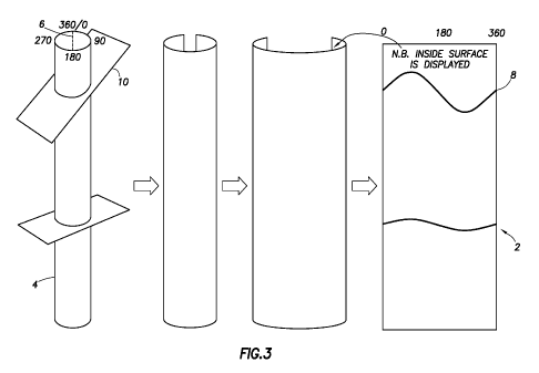
More specifically, FIG. 3, illustrates a borehole image 2 obtained from a
cylindrical
borehole 4. The image typically is a 2-dimensional representation of the inner
surface of the
borehole with reference to geographic or true north 6, or in the case of
highly angled
boreholes (see FIG. 4), to the borehole highside (i.e. upper part of the
borehole or top of hole
("TOH")). The dotted line represents true north, or in the case of a highly
inclined or
horizontal borehole 14, the borehole highside. Any dipping planar features
that intersect the
borehole 4, therefore, describe a sinusoid 8. And even in the case of an
inclined borehole 14,
the borehole axis 16 is displayed as though it is vertical. Accordingly, the
attitude 16 of the
observed sinewave represents the apparent dip.
Borehole images are generally far more complex than is represented in FIGS. 3
and 4.
This is explained, in part, by FIG. 5, which illustrates that, in reality,
plenty of intersections
CA 02864524 2014-08-13
WO 2013/122971 PCT/US2013/025806
11
between fractures and wells are incomplete ellipses because fractures may be
smaller than the
well, intersected by the well at their perimeter, or bed or fracture bounded.
Further, data
collected by appropriate logging tools, such as the FMITm tool referenced
above, is a
combined response of a formation that may include various types of features,
both incomplete
and complete. Decomposition of such complex data distributions into meaningful
information about the formation is challenging, for example with respect to
determining P32.
Josselin Kherroubi and colleagues at Schlumberger, the assignee of the present
application, propose a method to automatically extract linear segments from
borehole images
and evaluate which of those segments belong to fractures. (See, J. Kherroubi,
A Etchecopar:
"Fracture Characterization from Borehole Image: A Quantified Approach," AAPG
Annual
Convention & Exhibition, Denver USA 2009 and J. Kherroubi, "Automatic
Extraction of
Natural Fracture Traces from Borehole Images, 19th International Conference on
Pattern
Recognition (IAPR), Tampa, Fl, USA, 2008), which are both herein incorporated
by
reference in their entirety. However, the fracture surface to assess P32
cannot be directly
calculated because the planes bearing the segments are not defined.
The present disclosure provides systems and methods for evaluating P32 after
linear
segments are extracted from borehole images. Although the Kherroubi et al.
approach is
mentioned herein for extracting segments of fractures from the borehole image,
any
methodology for extracting linear segments from the borehole image (or from
the borehole
data) and/or evaluating whether the segments correspond to fractures can be
used as the basis
for the further data analysis provided in this disclosure.
In general, in some embodiments, the methods herein are directed at estimating
surface of fracture per volume of rock (P32) from a borehole image taken in a
borehole, which
CA 02864524 2014-08-13
WO 2013/122971 PCT/US2013/025806
12
includes data relating to segments of fractures occupying one or more planes,
without the
need for defining the one or more planes bearing the segments. In some
embodiments, the
borehole image is in the form of a zonal resistivity map such as can be
generated with an
FMITm, RABTM or ARCTM tool as referenced above. In further embodiments,
estimating P32
involves extracting linear segments corresponding to fractures from the
borehole image (e.g.
the zonal resistivity map), sorting the segments into angular classes (each
angular class, as
explained in more detail below, is a grouping of fracture apparent dips and
segment angles
spanning a predetermined range), generating an actual cumulated segment length
distribution
over the angular classes, correlating the actual cumulated segment
distribution with a
theoretical segment length distribution for each of the angular classes to
obtain the length of
fracture segment per surface of borehole (P21) contributions of each angular
class
computing a P32 for each angular class (P32(x'Y)) from each P2i(x'Y), and
summing together the
computed P32 for each class to arrive at a total P32 (p32(tot)).
In general, in some embodiments, the systems according to the disclosure
include: 1)
a downhole tool that acquires data relating to fracture segments and from
which the length
and dip angle of the fracture segment may be extracted; and 2) a processor
including
machine-readable instructions for estimating surface of fracture per volume of
rock (P32)
from the data, without the need for defining the one or more planes bearing
the segments. In
further embodiments, the estimating involves reconstructing theoretical
elliptical fractures
from the segment data, calculating length of fracture segment per surface of
borehole (P21)
for each of the theoretical elliptical fractures, and deriving P32 from P21.
In yet further
embodiments, the processor further includes machine-readable instructions for
calculating an
actual distribution of cumulative fragment length by angular class and
reconstructing
theoretical elliptical fractures by correlating the actual distribution of
cumulative fragment
length with a theoretical distribution of fragment length for each angular
class.
CA 02864524 2014-08-13
WO 2013/122971 PCT/US2013/025806
13
FIG. 6 illustrates a baseline concept for generating the theoretical segment
length
distribution for each of the angular classes. In the example herein, nine
angular classes are
chosen with equal spans of 10 degrees (ranging from 0-10 to 80-90). However,
with respect
to the systems and methods disclosed herein, the span of angular classes can
be arbitrarily
chosen. A larger or smaller number of angular classes can be used, and the
classes do not
need to be equal in span (i.e. they can have different span widths). In
general, precision can
be improved by reducing the span of the classes (i.e. increasing the number of
classes). At
the same time, increasing the number of classes may increase the computational
time. At a
certain point the additional precision provided by additional classes becomes
smaller while
the computation effort becomes larger. In addition, image resolution may also
contribute to
the choice of number of classes and the width of a class (or classes). For
example, in some
embodiments, the borehole image is acquired by an FMITm tool with a dip angle
resolution of
+/- 0.1 degree so decreasing the span under such a value would not be
meaningful.
Understanding these principles, a person of skill can chose a number of
classes appropriate
for their purposes.
The theoretical segment length distribution means the segment length
distribution for
complete ellipses spanning an angular class. As a baseline, as shown in FIG.
6, the
intersection between a fracture and a borehole can be characterized as a
segment collection.
The full intersection of a planar fracture and a well corresponds to a
complete ellipse, which
appears as a sinusoid on a 2D unrolled display (FIG. 6b). This sinusoid can be
divided into
elementary segments, characterized by a length and a segment angle. The
"segment angle" is
the angle of the segment with respect to the cross-sectional plane (i.e. the
horizontal direction
on the 2D display).
CA 02864524 2014-08-13
WO 2013/122971 PCT/US2013/025806
14
As previously indicated, for convenience, the segment angles and the fracture
apparent dips are gathered into angular classes. The "fracture apparent dip"
is the apparent
angle of the fracture with respect to the cross-sectional plane. In the
example herein, as also
previously indicated, angular classes are chosen to span the same width
covering 10 degrees
each. Therefore, there are nine angular classes ranging from 0-10 up to 80-90.
The
distribution of the segment length in these nine classes is unique for each
fracture apparent
dip, and is further independent of azimuth. As a person of skill may
appreciate, 90 degrees
itself is excluded from any class because that would correspond to a vertical
fracture of
infinite length. Therefore the range of a given class includes the lower
boundary but excludes
the upper boundary. In other words the class ranging, for example, from 20-30
degrees
includes 20 degrees but excludes 30 degrees.
FIG. 7 provides the theoretical distribution of the nine fracture apparent dip
classes
(i.e. theoretical segment length vs. angle distribution for the nine classes
of fracture apparent
dip). As is evident, for a given angular class, there are no segments
belonging to an angular
class above the fracture apparent dip, and there are always segments in the
class
corresponding to the fracture dip. As a consequence, the segment with the
highest dip
indicates the dip of the highest fracture plane; in other words, the steepest
dipping segments
of an actual distribution belongs to fractures with an apparent dip in the
same angular class.
While FIG. 7 provides theoretical distributions computed for complete
ellipses, in
reality plenty of intersections between fractures and wells are incomplete
ellipses because
fractures may be smaller than the well, intersected by the well at their
perimeter, bed or
fracture bounded. The present disclosure assumes that when the number of
segments is large,
the statistical distribution of their cumulated length vs. angle is
independent of fracture
CA 02864524 2014-08-13
WO 2013/122971
PCT/US2013/025806
dimensions. In other words, the segment distribution for numerous partially-
crossing
fractures is similar to that obtained for complete ellipses, as illustrated in
FIG. 5.
According to the present disclosure, P32 is estimated from actual cumulated
segment
length across angular class by using the theoretical distributions to
reconstruct theoretical full
ellipses from the collective actual segment fragments. More specifically,
linear segments are
extracted from the borehole image by any method, for example by the method of
Kherroubi
et al., referenced above. After the extraction is performed, an effort is made
to identify which
segments correspond to fractures, for example an interpreter filters and
discriminates which
of these segments correspond to fractures. The segments are then sorted with
respect to the
nine angular classes described above (or alternatively the number and type of
classes chosen).
The cumulated length for each class is then directly calculated, as shown in
FIG. 8.
After the actual cumulated segment length versus segment angular class is
calculated,
theoretical full ellipses are reconstructed and iteratively removed from the
data set by
correlating the theoretical distribution for each angular class (if it exists)
within the actual
data set and iteratively removing those theoretical sets from the data set.
More specifically, P21 is calculated for the whole segment population by
summing the
P21 contribution of each fracture apparent dip class. The individual
contribution of each class
is then evaluated. FIG. 9 illustrates an example of such an evaluation, as
follows:
1)
Identify the highest apparent dip class. With reference to the actual segment
distribution shown in FIG. 9A, the highest segment angle class in this
particular example is
the 70-80 degree class. As previously mentioned, the segments in the highest
angle class
belong to fractures with similar dip values (70-80 degrees).
CA 02864524 2014-08-13
WO 2013/122971 PCT/US2013/025806
16
2) Compute the length of segments belonging to the fractures of the highest
apparent dip class. As previously discussed, for a particular fracture dip
class, we can
generate the theoretical segment length distribution. From the borehole image,
we also know
the actual cumulated segment length in the highest angle class. Therefore, as
shown in FIG.
9B, the length of segments belonging to the fractures of the highest apparent
dip class can be
calculated in each of the lower segment angle classes. The sum of these
lengths (including
that of the highest segment angle class) gives the individual surface
contribution of the
fractures with the highest apparent dip. This contribution is denoted
P21(70480). Note that the
theoretical distributions do not need to be generated each time the process is
performed.
Rather the theoretical distributions can be computed once and, for example,
can be held in the
memory of the processor as a "look up" table to be used as a reference in
performing the
steps of this process.
3) Remove the correlated data from the actual data set. Once the cumulated
length for the highest apparent dip class is classified (in step 2), it is
removed from the actual
distribution. See FIGS. 9C and 9D.
4) Iteratively perform steps 1-3 for each angular class in descending
order. The
same process is iteratively carried out to assess the P21 from fractures in
other apparent dip
classes in an angular descending order. Thus, in this example, the process is
next carried out
for segments for the 60-70 degrees apparent dip class. (After identifying the
highest dip
class, step 1 becomes identify the next highest dip class.) A small proportion
of segments
may effectively remain unclassified at the end of the processing (i.e. they
are orphan
segments that are additional to the determined set of complete ellipses formed
by all the other
segments). These remainder segments are not included in the fractures surface
(P32)
calculation. However, because these orphan segments are few, any impact (if at
all) on the
CA 02864524 2014-08-13
WO 2013/122971 PCT/US2013/025806
17
approximation of P32 is generally acceptable and to the inventors knowledge
still provides the
best current approximation of P32.
5) Calculate P32("Y). At the end of all the iterations, we have the
P21 (the length
of fracture segment per surface of borehole) contributions of each fracture
apparent dip class,
from which P32 (the surface of fracture per volume of rock) can be derived. A
number of
methods have been proposed to correlate P21 to P32 using a "correction
coefficient" as
follows: P32 = P21* C. Thus, knowing this ratio (or correction coefficient)
and the previously
calculated P21 contribution of each fracture class, the individual P32 for
each fracture apparent
dip class is calculated as follows: p32(Y) = P21("Y) x Ratio
FIG. 10 provides a graph relating the correction coefficient to fracture
apparent dip.
Xiaohai Wang (2005): "Stereological Interpretation of Rock Fracture Traces on
Borehole
Walls and Other Cylindrical Surfaces," PhD thesis of the Virginia Polytechnic
Institute and
State University of Blacksburg, VA, which is hereby incorporated by reference
in its entirety,
describes one method of deriving this correction coefficient. Another method
of calculating
the correction coefficient is described below.
Computation of Correction Coefficient to Account for Dip:
Let us consider a borehole cylinder of height H and radius Rb, intersected by
a (fully-
crossing) planar fracture of apparent dip dip, as shown in FIG. 6a (wherein
dip is shown to
be 75 degrees).
Calculation of the fracture length per borehole surface P2i
The fracture trace on the borehole wall is a complete ellipse, which perimeter
P can
be approximated by the Ramanujan I formula as:
CA 02864524 2014-08-13
WO 2013/122971 PCT/US2013/025806
18
P 7r [3(a + b)¨\1(3a + b)(a +301
(1)
, where a is the great radius of the ellipse and b its small radius. In our
particular
case, those radii are expressed as:
a= _____________________________ Rband b = Rb
(2)
cos(dip)
Inserting these formulas in (1), we finally obtain:
7E R
P b f (3)
cos(dip)
,where f is a dimensionless coefficient, defined for dip < ¨ as:
2
f = 3(1+ cos(dip)) ¨ V(3 + cos(dip))(1+ 3cos(dip))
(4)
The fracture length per borehole surface P2i is defined by:
P=-(5)
S,
where Sb denotes the surface of the borehole cylinder, expressed as:
Sb = 2rrRbH
(6)
Inserting (3) and (6) into (5), we obtain a very good approximation of 12i :
P21 _____________________________________ (7)
2H cos(dip)
CA 02864524 2014-08-13
WO 2013/122971 PCT/US2013/025806
19
Calculation of the fracture surface per rock volume P32
The surface S of the fracture is calculated from the usual formula expressing
the
surface of an ellipse:
S = 7rab
(8)
Replacing again a and b by their respective expressions given in (2), we
obtain:
7r Rb2
S = ________________________________________________________________________
(9)
cos(dip)
The rock volume V initially present in the borehole cylinder before drilling
is:
Vb = rcRb2H
(10)
The fracture surface per rock volume P32 is defined by:
P32 = ¨
( 1 1 )
vb
Inserting (9) and (10) into (11), we obtain finally for P32:
1
1332 ______________________________________________________________________
(12)
H cos(dip)
Calculation of the P32 / P21 ratio
The correction coefficient, defined by C = P32 / P21 is calculated from (7)
and (12):
CA 02864524 2014-08-13
WO 2013/122971 PCT/US2013/025806
P 2
C = ¨
(13)
P21 f
,which finally results in:
2
C _________________________________________________________________________
(14)
3(1+ cos(dip))¨ V(3 + cos(dip))(1+ 3cos(dip))
It has to be noted that (14) is a very good approximation of the exact
expression of the
P32 / 1321 ratio (featuring a complete elliptical integral of the second kind)
defined in Wang.
Although in the particular example, the perimeter of an ellipse is
approximated by the
Ramanuhan I formula, any other formula providing an approximation of the
perimeter of an
ellipse, for example any other formula providing a very good approximation of
the perimeter
of an ellipse, can be used in the same manner to derive this coefficient.
The described methods for deriving P32 from P21 are exemplary only. Any
method for analyzing the relationship between P32 and P21 can be used in
accordance with the
systems and methods of this disclosure.
6) Calculate P32(t0t). The sum of all P32 individual contributions
gives the overall
(cumulated) P32 as follows: p32(tot) E (p32(O41o) p32(8o49o)).
A number of embodiments have been described. Nevertheless it will be
understood
that various modifications may be made without departing from the spirit and
scope of the
invention. Accordingly, other embodiments are included as part of the
invention and may be
encompassed by the attached claims. Furthermore, the foregoing description of
various
embodiments does not necessarily imply exclusion. For example, "some"
embodiments or
"other" embodiments may include all or part of "some", "other" and "further"
embodiments
within the scope of this invention.