Note: Descriptions are shown in the official language in which they were submitted.
CA 02864545 2014-09-23
APST-0192
DRILLING SYSTEM AND ASSOCIATED SYSTEM AND METHOD FOR MONIT,ORING,
CONTROLLING, AND PREDICTING VIBRATION IN AN UNDERGROUND DRILLING
OPERATION
TECHNICAL FIELD
[0001] The present disclosure relates to a drilling system for underground
drilling, and
more particularly to a method for monitoring, controlling and predicting
vibration in a drilling
operation.
BACKGROUND
[0002] Underground drilling, such as gas, oil, or geothermal drilling,
generally involves
drilling a bore through a formation deep in the earth. Such bores are formed
by connecting a drill bit
to long sections of pipe, referred to as a "drill pipe," so as to form an
assembly commonly referred
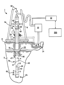
to as a "drill string." The drill string extends from the surface to the
bottom of the bore. The drill
bit is rotated so that the drill bit advances into the earth, thereby forming
the bore. In rotary drilling,
the drill bit is rotated by rotating the drill string at the surface. Pumps at
the surface pump high-
pressure drilling mud through an internal passage in the drill string and out
through the drill bit. The
drilling mud lubricates the drill bit, and flushes cuttings from the path of
the drill bit. In some cases,
the flowing mud also powers a drilling motor, commonly referred to as a "mud
motor," which turns
the bit. In any event, the drilling mud flows back to the surface through an
annular passage formed
between the drill string and the surface of the bore. In general, optimal
drilling is obtained when the
rate of penetration of the drill bit into the formation is as high as possible
while a vibration of
drilling system is as low as possible. The rate of penetration ("ROP") is a
function of a number of
variables, including the rotational speed of the drill bit and the weight-on-
bit ("WOB"). The drilling
environment, and especially hard rock drilling, can induce substantial
vibration and shock into the
drill string, which has an adverse impact of drilling performance.
[0003] Vibration is introduced by rotation of the drill bit, the motors used
to rotate the drill
bit, the pumping of drilling mud, imbalance in the drill string, etc.
Vibration can cause premature
failure of the various components of the drill string, premature dulling of
the drill bit, or may cause
the catastrophic failures of drilling system components. Drill string
vibration includes axial
vibration, lateral vibration and torsional vibration. "Axial vibration" refers
to vibration in the
direction along the drill string axis. "Lateral vibration" refers to vibration
perpendicular to the drill
string axis. Lateral vibration often arises because the drill string rotates
in a bent condition. Two
- 1 -
CA 02864545 2014-09-23
. APST-0192
other sources of lateral vibration are "forward" and "backward", or "reverse",
whirl. "Whirl" refers
to a situation in which the bit orbits around the borehole in addition to
rotating about its own axis.
In backward whirl, the bit orbits in a direction opposite to the direction of
rotation of the drill bit.
"Torsional vibration," also of concern in underground drilling, is usually the
result of what is
referred to as "stick-slip." Stick-slip occurs when the drill bit or lower
section of the drill string
momentarily stops rotating (i.e., "sticks") while the drill string above
continues to rotate, thereby
causing the drill string to "wind up," after which the stuck element "slips"
and rotates again. Often,
the bit will over-speed as it unwinds.
[0004] Various system can be used to obtain and process information concerning
a drilling
operation, which can help improve drilling efficiency. Systems have been
developed that can
receive and process information from sensors near the drill bit and then
transmit that information to
surface equipment. Other systems can determine vibration of the bottomhole
assembly, either
downhole during a drill run, or at the surface. Many of such systems use
finite element and/or finite
difference techniques to assist in in analysis of drilling data, including
vibration information.
SUMMARY
[00051 An embodiment of the present disclosure includes a method for
monitoring and
controlling a drilling system that includes a drill string and a drill bit
supported at a downhole end of
the drill string. The drilling system is configured to form a borehole in an
earthen formation. The
method comprising the step of predicting, via a drilling system model,
vibration information for the
drill string based on a set of drilling operating parameters, a borehole
information, and a drilling
system component information. The set of drilling operating parameters include
a weight-on-bit
(WOB) and a drill bit rotational speed. The drilling system component
information includes one or
more characteristics of the drill string and the drill bit. The predicted
vibration information includes
an amplitude for at least one of a axial vibration, lateral vibration, and a
torsional vibration of the
drill string. The drilling system model is configured to predict vibration
information based on an
energy balance of the drill string operating according to the set of drilling
operating parameters
during an expected drilling operation. The method includes operating the
drilling system to drill the
borehole in the earthen formation according to the set of drilling operating
parameters and obtaining
data in the borehole during the drilling operation, the data being indicative
at least one of the axial
vibration, lateral vibration, and a torsional vibration of the drill string.
The method includes
comparing the predicted vibration information for the drill string and the
drill bit to the measured
- 2 -
CA 02864545 2014-09-23
APST-0192
vibration information for the drill string and the drill bit, and if the step
of comparing results in a
difference between the expected and measured vibration information for each of
the drill string and
the drill bit, updating the drilling system model to reduce the difference
between the expected and
measured vibration information for the drill string and the drill bit.
100061 Another embodiment of the present disclosure is a drilling system
configured to
form a borehole in an earthen formation during a drilling operation. The
drilling system includes a
drill string supporting a drill bit. The drill bit configured to defined the
borehole. The drilling
system includes a plurality of sensors configured to obtain drilling operation
information and
measured vibration information, wherein one or more of the plurality of
sensors are configured to
obtain, in the borehole during the drilling operation, data that is indicative
the axial vibration, lateral
vibration, and a torsional vibration of the drill string, the obtained data
indicative of the measured
vibration information. The drilling system includes at least one computing
device including a
memory portion having stored thereon drilling system component information,
the drilling system
component information including one or more characteristics of the drill
string, the memory portion
further including expected operating information for the drilling operation,
the expected operating
information including at least a weight-on-bit (WOB), a rotational speed of
the drill bit, a borehole
diameter, and a vibration damping coefficient. The drilling system further
includes a computer
processor in communication with the memory portion, the computer processor
configured to predict
vibration information for the drill string, the predicted vibration
information including at least a
predicted amplitude for at least one of an axial vibration, a lateral
vibration, and a torsional vibration
of the drill string, the predicted vibration information being based on the
drilling system component
information and an energy balance of the drill string operating according to
the expected operation
information for the drilling operation. The computing processor being further
configured to
compare the predicted vibration information for the drill string and the drill
bit to the measured
vibration information for the drill string and the drill bit, wherein the
computing device is configured
to update the drilling system model if there a difference between the expected
and measured
vibration information is detected.
BRIEF DESCRIPTION OF THE DRAWINGS
[0007] The foregoing summary, as well as the following detailed description of
illustrative
embodiments of the present application, will be better understood when read in
conjunction with the
- 3 -
CA 02864545 2014-09-23
APST-0192
appended drawings. For the purposes of illustrating the present application,
there is shown in the
drawings illustrative embodiments. It should be understood, however, that the
application is not
limited to the precise arrangements and instrumentalities shown. In the
drawings:
[0008] FIG. 1 is a schematic of an underground drilling system according to an
embodiment of the present disclosure;
[0009] FIG. 2A is a block diagram of a computing device used in the drilling
system
shown in FIG. 1;
[0010] FIG. 2B is a block diagram illustrating a network of one or more
computing devices
and a drilling data database of the drilling system shown in FIG. 1;
[0011] FIG. 3A is a block diagram illustrating a method of operating a
drilling system
shown in Fig. 1, according to an embodiment of the present disclosure;
[0012] FIG. 3B is a block diagram illustrating a method of creating a drilling
system
model, according to an embodiment of the present disclosure;
[0013] FIG. 4 is a block diagram illustrating a method for revising the drill
system model
based on the difference between the predicting vibration information and the
measured vibration
information;
[0014] FIG. 5 is a block diagram illustrating a method for revising the
drilling system
model to reduce deviations between predicted and measured vibration according
to an embodiment
of the present disclosure; and
[0015] FIG. 6 is a block diagram illustrating a method for operating a
drilling system
shown in FIG. 1 in order to attain a desired rate of penetration and avoid
excessive vibration;
[0016] FIG. 7 is an exemplary computer generated display of an energy balance
of a
drilling system illustrating amplitude as a function of input load, according
to the present disclosure;
[0017] FIG. 8 is a computer generated display for an exemplary vibratory mode
shape
curve generated according to the present disclosure;
[0018] FIG. 9 is a computer generated display for an exemplary critical speed
map
generated according to the present disclosure;
DETAILED DESCRIPTION OF ILLUSTRATIVE EMBODIMENTS
[0019] Referring to FIG. 1, a drilling system or drilling rig 1 is configured
to drill a
borehole 2 in an earthen formation 3 during a drilling operation. The drilling
system 1 includes a
drill string 4 for forming the borehole 2 in the earthen formation 3, a
drilling data system 12, and at
-.4-
CA 02864545 2014-09-23
APST-0192
least one computing device 200. The computing device 200 can host one or more
drilling operation
applications, for instance software applications, that are configured to
perform various methods for
monitoring the drilling operation, controlling the drilling operation,
predicting vibration information
concerning the drilling operation, and/or predicting vibration information
concerning the drill string
4 for use in a drilling operation. The computing device 200 cooperates with
the drilling data system
12 and the one or more software application to execut the various methods
described herein. While
the borehole 2 is illustrated as a vertical borehole, the systems and methods
described herein can be
used for a directional drilling operation, i.e, horizontal drilling. For
instance, the drill string 4 can be
configured to form a borehole 2 in the earthen formation 3 that is orientated
along a direction that is
transverse to an axis that is perpendicular to the surface 11 of the earthen
formation 3.
[0020] Continuing with FIG. 1, the drilling system or rig 1 includes a derrick
9 supported
by the earth surface 11. The derrick 9 supports a drill string 4. The drill
string 4 has a top end 4a, a
bottom end 4b, a top sub 45 disposed at the top end 4a of the drill string 4,
and a bottomhole
assembly 6 disposed at the bottom end 4b of the drill string 4. The bottomhole
assembly 6 includes
top end 6a and a bottom end 6b. A drill bit 8 is coupled to the bottom end 6b
of a bottomhole
assembly 6. The drilling system 1 has a prime mover (not shown), such as a top
drive or rotary
table, configured to rotate the drill string 4 so as to control the rotational
speed (RPM) of, and torque
on, the drill bit 8. Rotation of the drill string 4 and drill bit 8 thus
defines the borehole 2. As is
conventional, a pump 10 is configured to pump a fluid 14, for instance
drilling mud, downward
through an internal passage in the drill string 4. After exiting at the drill
bit 8, the returning drilling
mud 16 flows upward to the surface 11 through an annular passage formed
between the drill
string 4 and the borehole 2 in the earthen formation 3. A mud motor 40, such
as a helicoidal positive
displacement pump or a "Moineau-type" pump, may be incorporated into the
bottomhole
assembly 6. The mud motor is driven by the flow of drilling mud 14 through the
pump and around
the drill string 4 in the annular passage described above.
[0021] A drilling operation as used herein refers to one more drill runs that
define the
borehole 2. For instance a drilling operation can include a first drill run
for defining a vertical
section of the borehole 2, a second drill run for defining the bent section of
the borehole 2, and a
third drill run for defining a horizontal section of the borehole 2. More than
three drill runs are
possible. For difficult drilling operations, as much as 10 to 15 drill runs
may be completed to define
the borehole 2 for hydrocarbon extraction purposes. It should be appreciated
that one or more
- 5 -
CA 02864545 2014-09-23
APST-0192
bOttomhole assemblies can be used for each respective drill run. The systems,
methods, software
applications as described herein can be used to execute methods that monitor,
control, and predict
vibration information the drilling operation, as well as monitor, control, and
prediction vibration
information for specific drilling runs in the drilling operation.
[0022] In the illustrated embodiment, the computing device 200 can host the
software
application that is configured to predict vibration information for the drill
string 4 using a drilling
system model, as will be further detailed below. The vibration information can
include the axial,
lateral and torsional vibration information of the drill string 4, and
specifically, the mode shape and
frequency for each of an axial, lateral, and torsional vibration of the drill
string 4. It should be
appreciated that vibration mode shape is indicative of the relative
displacements along the drill
string. As an advancement on prior systems, the software application as
described herein can
predict vibration information noted above based on the drill string geometry,
the applied drilling
loads based on the expected drilling operation (e.g. expected weight-on-bit,
rotary speed and flow
rate). In predicting vibration information, the software application takes
into account the energy
balance to determine the vibration severity based on a frequency domain type
of finite element
technique, as further detailed below. A software application based on the
energy balance of the
drilling system 1, as opposed to a software application that uses various
finite element techniques
based on time domain, result in significant processing time improvements. The
software
applications ability to revise predicted vibration information based on real-
time data from a drilling
operation, as discussed below, results in more precise and accurate drilling
operation information
that the rig operator or drill string designer can reply upon. During a
drilling operation, the software
application described herein can be used predict anticipated drilling
dysfunctions, such a component
wear and potential lost time incidents due to component replacement, and can
further determine
modified drilling set points to avoid the drilling dysfunction. Further, the
software application can
predict vibration information for the drill string 4, access data indicative
of the measured vibration
of the drill string 4, and revise the predicted vibration information in the
event there is a difference
between the predicted vibration information and the measured vibration, as
will be further cjetailed
below.
[0023] Referring to FIG. 1, the drilling system 1 can include a plurality of
sensors
configured to measure drilling data during a drilling operation, for use in
methods described herein.
Drilling data can include expected operating parameters, for instance the
expected operating
- 6 -
CA 02864545 2014-09-23
APST-0192
parameter for WOB, rotary speed (RPM) and the drill bit rotational speed
(RPM). In the illustrated
embodiment, the drill string top sub 45 includes one or more sensors for
measuring drilling data.
For instance, the one or more sensors can be strain gauges 48 that measure the
axial load (or hook
load), bending load, and torsional load on the top sub 45. The tob sub 45
sensors also include a
triaxial accelerometer 49 that senses vibration at the top end 4a of the drill
string 4.
= [0024] Continuing with FIG. 1, the bottomhole assembly 6 can also include
one of more
sensors that are configured to measure drilling parameters in the borehole 2.
In addition, the
bottomhole assembly 6 includes a vibration analysis system 46 configured to
determine various
vibration parameters based on the information regarding the drilling operation
obtained from the
sensors in the borehole. The vibration analysis module will be further
detailed below. The
bottomhole assembly sensors can be in the form of strain gauges,
accelerometers, pressure gauges
and magnetometers. For instance, the bottomhole assembly 6 can include
downhole strain gauges 7
that measure the WOB. A system for measuring WOB using downhole strain gauges
is described in
U.S. Pat. No. 6,547,016, entitled "Apparatus For Measuring Weight And Torque
An A Drill Bit
Operating In A Well," hereby incorporated by reference herein in its entirety.
In addition, the strain
gauges 7 can be configured to measure torque on bit ("TOB") and bending on bit
("BOB") as well
as WOB. In alternative embodiments, the drill string can include a sub (not
numbered) incorporating
sensors for measuring WOB, TOB and BOB. Such a sub can be referred to as a
"WTB sub."
[0025] Further, the bottomhole assembly sensors can also include at least one
magnetometer 42. The magnetometer is configured to measure the instantaneous
rotational speed of
the drill bit 8, using, for example, the techniques in U.S. Pat. No.
7,681,663, entitled "Methods And
Systems For Determining Angular Orientation Of A Drill String," hereby
incorporated by reference
herein in its entirety. The bottomhole assembly sensors can also include
accelerometers 44, oriented
along the x, y, and z axes (not shown) (typically with 250 g range) that are
configured to measure
axial and lateral vibration. While accelerometer 44 is shown disposed on the
bottomhole assembly
6, it should be appreciated that multiple accelerometers 44 can be installed
at various locations along
the drill string 4, such that axial and lateral vibration information at
various location along the drill
string can be measured.
[0026] As noted above, the bottomhole assembly 6 includes a vibration analysis
system 46.
The vibration analysis system 46 is configured to receive data from the
accelerometers 44
concerning axial and lateral vibration of the drill string 4. Based on the
data receive from the
- 7 -
CA 02864545 2014-09-23
, APST-0192
accelerometers, the vibration analysis system 46 can determine the measured
amplitude and mode
shape of axial vibration, and of lateral vibration due to forward and backward
whirl, at the location
of the accelerometers on the drill string 4. The measured amplitude and
frequency of axial vibration
and of lateral vibration can be referred to as measured vibration information.
The measured
vibration information can also transmitted to the surface 11 and processed by
drilling data system 12
and /or the computing device 200. The vibration analysis system 46 can also
receive data from the
magnetometer 42 concerning the instantaneous rotational speed of the drill
string at the
magnetometer 42 location. The vibration analysis system 46 then determines the
amplitude and
frequency of torsional vibration due to stick-slip. The measured frequency and
amplitude of the
actual torsional vibration is determined by calculating the difference between
and maximum and
minimum instantaneous rotational speed of the drill string over a given period
of time. Thus, the
measured vibration information can also refer to the measured torsional
vibration.
[0027] According to the present disclosure, to reduce data transmissions for
vibration
information, drilling data may be grouped into ranges and simple values used
to represent data in
these ranges. For example, vibration amplitude can be reported as 0, 1, 2 or 3
to indicate normal,
high, severe, or critical vibration, respectively. One method that may be
employed to report
frequency is to assign numbers 1 through 10, for example, to values of the
vibration frequency so
that a value of 1 indicates a frequency in the 0 to 100 hz range, a value of 2
indicates frequency in
the 101 to 200 hz range, etc. The mode of vibration may be reported by
assigning a number 1
through 3 so that, for example, a value of 1 indicates axial vibration, 2
indicates lateral vibration,
and 3 indicates torsional vibration. If only such abbreviated vibration data
is transmitted to the
surface, at least some of the data analysis, such as a Fourier analysis used
in connection with the use
of backward whirl frequency to determine borehole diameter, could be performed
in a processor
installed in the bottomhole assembly 6. {Note: Currently we don't do this, but
have thought about
implementing it in the future}
[0028] The bottom hole assembly sensors can also include at least first and
second pressure
sensors 51 and 52 that measure the pressure of the drilling mud flowing
through drilling system
components in the borehole 2. For instance, the first and second sensors 51
and 52 measure pressure
of the drilling mud flowing through the drill string 4 (in a downhole
direction), and the pressure of
the drilling mud flowing through the annular gap between the borehole wall and
the drill string 4 in
an up-hole direction, respectively. Differential pressure is referred to as
the difference in pressure
- 8 -
CA 02864545 2014-09-23
APST-0192
between the drilling mud following in downhole direction and the drilling mud
flowing in the up-
hole direction. Sometimes differential pressure can be referred to as the
difference in off-bottom and
on-bottom pressure, as is known in the art. Pressure information can be
transmitted to the drilling
data acquisition system 12 and/or computing device 200. In the illustrated
embodiment, the first and
second pressure sensors 51 and 52 can be incorporated in the vibration
analysis system 46.
[0029] Further, the drilling system 1 can also include one or more sensors
disposed on the
derrick 9. For instance, the drilling system can include a hook load sensor 30
for determining WOB
and an additional sensor 32 for sensing drill string rotational speed of the
drill string 4. The hook
load sensor 30 measures the hanging weight of the drill string, for example,
by measuring the
tension in a draw works cable (not numbered) using a strain gauge. The cable
is run through three
supports and the supports put a known lateral displacement on the cable. The
strain gauge measures
the amount of lateral strain due to the tension in the cable, which is then
used to calculate the axial
load, and WOB. In another embodiment, drill data can be obtained using an
electronic data
recorder (EDR). The EDR can measure operating loads at the surface. For
instance, the EDR can
use sensors to measure the hook load (tensile load to of the drill string at
the surface), torque,
pressure, differential pressure, rotary speed, flow rate. The weight-in-bit
(WOB) can be cal-culated
from the hook load, drill string weight, and off-bottom to on-bottom
variations of load. Torque can
measured from the motor current draw. Flow rate can be based on the counts the
pump strokes and
the volume pumped per stroke. The differential pressure is the difference
between on-bottom and
off-bottom pressure.
[0030] The drilling data system 12, as will be further detailed below, can be
a computing
device in electronic communication with the computing device 200. The drilling
data system 12 is
configured to receive, process, and store various drilling operation
information obtained from the
downhole sensors described above. Accordingly, the drilling data system 12 can
include various
systems and methods for transmitting data between drill string components and
the drilling data
system 12. For instance, in a wired pipe implementation, the data from the
bottomhole assembly
sensors is transmitted to the top sub 45. The data from the top sub 45
sensors, as well as data from
the bottomhole assembly sensors in a wired pipe system, can be transmitted to
the drilling data
system 12 or computing device 200 using wireless telemetry. One such method
for wireless
telemetry is disclosed in U.S. application Ser. No. 12/389,950, filed Feb. 20,
2009, entitled
"Synchronized Telemetry From A Rotating Element," hereby incorporated by
reference in its
- 9 -
CA 02864545 2014-09-23
APST-0192
entirety. In addition, the drilling system 1 can include a mud pulse telemetry
system. For instance,
a mud pulser 5 can be incorporated into the bottomhole assembly 6. The mud
pulse telemetry
system encodes data from downhole equipment, such as vibration information
from the vibration
analysis system 46 and, using the pulser 5, transmits the coded pulses to the
surface 11. Further,
drilling data can be transmitted to the surface using other means such as
acoustic or electromagnetic
transmission.
[0031] Referring to FIG. 2A, any suitable computing device 200 may be
configured to host
a software application for monitoring, controlling and prediction vibration
information as described
herein. It will be understood that the computing device 200 can include any
appropriate device,
examples of which include a desktop computing device, a server computing
device, or a portable
computing device, such as a laptop, tablet or smart phone. In an exemplary
configuration illustrated
in FIG. 2A, the computing device 200 includes a processing portion 202, a
memory portion 204, an
input/output portion 206, and a user interface (UI) portion 208. It is
emphasized that the block
diagram depiction of computing device 200 is exemplary and not intended to
imply a specific
implementation and/or configuration. The processing portion 202, memory
portion 204,
input/output portion 206 and user interface portion 208 can be coupled
together to allow
communications therebetween. As should be appreciated, any of the above
components may be
distributed across one or more separate devices and/or locations. For
instance, any one of the
processing portion 202, memory portion 204, input/output portion 206 and user
interface portion
208 can be in electronic communication with the drilling data system 12, which
as noted above can
be a computing device similar to computing device 200 as described herein.
Further, any one of the
processing portion 202, memory portion 204, input/output portion 206 and user
interface portion
208 can be capable of receiving drill data from one or more the sensors and/or
the vibration analysis
system 46 disposed on the drill string 4.
[0032] In various embodiments, the input/output portion 106 includes a
receiver of the
computing device 200, a transmitter of the computing device 200, or an
electronic connector for
wired connection, or a combination thereof The input/output portion 206 is
capable of receiving
and/or providing information pertaining to communication with a network such
as, for example, the
Internet. As should be appreciated, transmit and receive functionality may
also be provided by one
or more devices external to the computing device 200. For instance, the
input/output portion 206 can
- 10-
=
CA 02864545 2014-09-23
APST-0192
be in electronic communication with the data acquisition system 12 and/or one
or more sensors
disposed on the bottomhole assembly 6 downhole.
[0033] Depending upon the exact configuration and type of processor, the
memory portion
204 can be volatile (such as some types of RAM), non-volatile (such as ROM,
flash memory, etc.),
or a combination thereof. The computing device 200 can include additional
storage (e.g., removable
storage and/or non-removable storage) including, but not limited to, tape,
flash memory, smart
cards, CD-ROM, digital versatile disks (DVD) or other optical storage,
magnetic cassettes, magnetic
tape, magnetic disk storage or other magnetic storage devices, universal
serial bus (USB) compatible
memory, or any other medium which can be used to store information and which
can be accessed by
the computing device 200.
[0034] The computing device 200 can contain the user interface portion 208,
which can
include an input device 209 and/or display 213 (input device 210 and display
212 not shown), that
allows a user to communicate with the computing device 200. The user interface
208 can include
inputs that provide the ability to control the computing device 200, via, for
example, buttons, soft
keys, a mouse, voice actuated controls, a touch screen, movement of the
computing device 200,
visual cues (e.g., moving a hand in front of a camera on the computing device
200), or the like. The
user interface 208 can provide outputs, including visual information, such as
the visual indication of
the plurality of operating ranges for one or more drilling parameters via the
display 213. Other
outputs can include audio information (e.g., via speaker), mechanically (e.g.,
via a vibrating
mechanism), or a combination thereof In various configurations, the user
interface 208 can include
a display, a touch screen, a keyboard, a mouse, an accelerometer, a motion
detector, a speaker, a
microphone, a camera, or any combination thereof. The user interface 208 can
further include any
suitable device for inputting biometric information, such as, for example,
fingerprint information,
retinal information, voice information, and/or facial characteristic
information, for instance, so to
require specific biometric information for access the computing device 200.
[0035] Referring to FIG. 2B, an exemplary and suitable communication
architecture is
shown that can facilitate monitoring a drilling operation of the drilling
system 1. Such an exemplary
architecture can include one or more computing devices 200, 210 and 220 each
of which can be in
electronic communication with a database 230 and a drilling data acquisition
system 12 via common
communications network 240. The database 230, though schematically represented
separate from
the computing device 200 could also be a component of the memory portion 104
of the computing
-11-
CA 02864545 2014-09-23
APST-0192
device 200. It should be appreciated that numerous suitable alternative
communication architectures
are envisioned. Once the drilling control and monitoring application has been
installed onto the
computing device 200, such as described above, it can transfer information
between other
computing devices on the common network 240, such as, for example, the
Internet. For ing`tance
configuration, a user 24 may transmit, or cause the transmission of
information via the network 240
regarding one or more drilling parameters to the computing device 210 of a
supplier of the
bottomhole assembly 6, or alternatively to computing device 220 of another
third party (e.g., a
drilling system owner 1) via the network 240. The third party can view, via a
display, the plurality
of operating ranges for the one or more drilling parameters as described
herein.
[0036] The computing device 200 and the database 230 depicted in Fig. 2B may
be
operated in whole or in part by, for example, a rig operator at the drill
site, a drill site owner, drilling
company, and/or any manufacturer or supplier of drilling system components, or
other service
provider, such as a third party providing drill string design services. As
should be appreciated, each
of the parties set forth above and/or other relevant parties may operate any
number of respective
computers and may communicate internally and externally using any number of
networks including,
for example, wide area networks (WAN's) such as the Internet or local area
networks (LAN's).
Database 230 may be used, for example, to store data regarding one or more
drilling parameters, the
plurality of operating ranges from a previous drill run, a current drill run,
and data concerning the
models for the drill string components. Further it should be appreciated that
"access" or "accessing"
as used herein can include retrieving information stored in the memory portion
of the local
computing device, or sending instructions via the network to a remote
computing device so as to
cause information to be transmitted to the memory portion of the local
computing device for access
locally. In addition or alternatively, accessing can including accessing
information stored in the
memory portion of the remote computing device.
[0037] Turning to FIG. 3A, according to an illustrated embodiment, a method 50
for
monitoring, controlling of drilling data, and the prediction vibration
information for a drilling
operation is initiated in step 100. In step 100, a user can input drilling
component data. For
instance, the user may specify a drill string component, for instance a
bottomhole assembly or
Measurement While Drilling ("MWD") tool, and the vibration limits applicable
to each such
component. The drill string and/or bottomhole assembly data can be input by
the operator or stored
- 12 -
CA 02864545 2014-09-23
APST-0192
in database 230 or in memory of the computing device 100. Bottomhole assembly
data can be
accessed as noted above by the software application. Data input in step 100
may include:
(i) the outside and inside diameters of the drill pipe sections that make up
the drill string,
(ii) the locations of stabilizers,
(iii) the length of the drill string,
(iv) the inclination of the drill string,
(v) the bend angle if a bent sub is used,
(vi) the material properties, specifically the modulus of elasticity, material
density, torsional
modulus of elasticity, and Poisson's ratio,
(vii) the mud properties for vibration damping, specifically, the mud weight
and viscosity,
(viii) the borehole diameters along the length of the well,
(ix) the azimuth, build rate and turn rate,
(x) the diameter of the drill bit and stabilizers, and
(xi) information concerning the characteristics of the formation, such as the
strike and dip.
[0038] In alternative embodiments, during step 100, the information concerning
the drill
string components can also be updated by the operator each time a new section
of drill string is
added or when a new drill run is initiated.
[0039] In step 101, expected operating information for the drilling operation
can be input
in the software application and stored as need in drilling data system or
computing device 100.
Expected operating information can developed at drill site or can be
determined according to a
drilling plan. Expected operating information includes (i) the WOB, (ii) the
drill string rotational
speed, (iii) the mud motor rotation speed, (iv) the diameter of the borehole,
and (v) any damping
coefficients.
[0040] In step 102, the software application predicts the vibration
information for the drill
string. The predicted vibration information includes at least an amplitude for
each of an axial
vibration, a lateral vibration, and a torsional vibration of the drill string
4. As will be further detailed
below and illustrated in FIG. 3B, the prediction of the vibration information
is based on the drilling
system component information and an energy balance method of the drill string
operating according
to the expected operation information for the drilling operation. In addition,
the prediction vibration
information can include frequency and mode shape information. During step 102,
the software
application can also initiate one or more analyses for use in the prediction
model discussed below.
- 13 -
CA 02864545 2014-09-23
APST-0192
In particular, the software application can conduct a static bending analysis
to determine the bending
information of the bottomhole assembly 6. The bending information includes
calculated bottomhole
assembly deflections, the side forces along the length of the bottomhole
assembly, the bending
moments, and the nominal bending stress. The software application also
performs a so-called
"predict analysis" in which it uses the bending analysis information to
predict the direction in which
the drill string will drill.
[0041] In step 104, the software application calculates vibration warning
limits for specific
drill string components based on the vibration information measured by the
sensors in the vibration
analysis system 46. For example, as discussed below, based on the predicted
mode shapes, the
software application can determine what level of measured vibration at the
accelerometer locations
would result in excessive vibration at the drill string location of a critical
drilling string component.
[0042] In step 106, the drilling operation continues or is initiated. For
instance, one or
more the previous steps, for instance steps 100 through 104, could be
initiated prior to a drilling
operation to help develop a drilling plan or and aid in designing a bottomhole
assembly.
[0043] In step 108, the software application can receive drilling data from
the rig surface
sensors. In step 109, the software application can receive drilling data from
the downhole sensors.
It should be appreciated that the rig surface drilling data and the downhole
drilling data may be
stored in computer memory in the drilling data system 12 and/or computing
device 200. The
communication system can transmit the drilling data from the rig surface
sensors and the downhole
sensors to the drilling data system 12. Drilling data from the surface sensors
are preferably
transmitted to the system 12 continuously. Drilling data from the downhole
sensors is transmitted to
the drilling data system 12 whenever downhole drilling data is sent to the
surface, preferably at least
every few minutes. The software application can then access the rig surface
drilling data and the
downhole drilling data. Regardless of whether the software application
accesses or receives drilling
data, the drilling data can be used by the software application on an on-going
basis during the
drilling operation.
[0044] In step 110, drilling data and drilling status can be transmitted to a
remote
computing device, for instance a remote computing device 210 (FIG. 2B). Users
not located at the
rig site can download and review the data, for example by logging into the
computing device 210,
and accessing the drilling data via the communications network 240, such as
the interne. In step
112, the software application determines whether any of the drilling
parameters input into software
- 14 -
CA 02864545 2014-09-23
APST-0192
application have changed. If the drilling parameters have changed, the
software application updates
the drilling data accordingly. Further, if the drilling parameters have not
changed, in block 114, an
optional lost performance analysis can be run, for instance similar to the
lost performance analysis
disclosed in U.S. Patent No. 8,453,764, herein incorporated by reference.
Process control can be
transferred and the method 701 shown in FIG. 5 can be initiated, as will be
further detailed,below.
[0045] Turning to FIG. 3B, which illustrates a method 70 for predicting
vibration
information for a drilling system. It should be appreciated that aspect of the
method 70 can be
performed prior to or along with steps 100 through 102 discussed above. FIG.
3B illustrates how a
drilling system model can be developed and used in a drilling operation.
Accordingly, each and
every step of method 70 need not be performed at the rig site or during a
drilling operation, but
could occur before a drilling operation.
[0046] Continuing with FIG. 3B, the method 70 initiates in step 260, by
defining a drilling
system model using finite element techniques, as further detailed below. In
step 260, the method
can included accessing drilling system component data. The drilling system
component data
includes one or more characteristics of the drill string typically used in
finite element models. The
one or more characteristics of the drill string include drill string geometry
data. Drill string
geometry data includes the outside and inside diameters of the drill pipe
sections that make up the
drill string, the locations of stabilizers, the length of the drill string,
the inclination of the drill string,
the bend angle if a bent sub is used, the diameter of the drill bit and
stabilizers. Drill string
geometry data also includes the material properties of drill string
components, specifically the
modulus of elasticity, material density, torsional modulus of elasticity, and
Poisson's ratio, as well
as a vibration damping coefficient, based on the properties of the drilling
mud properties,
specifically, the mud weight and viscosity. In step 262, the software
application can access borehole
information. Borehole information can include borehole diameters along the
length of the borehole,
the azimuth, build rate, turn rate, information concerning the characteristics
of the formation, such as
the strike and dip.
[0047] Continuing with FIG. 3B, in steps 266 to 272, the components of the
drill system
model is further processed using finite element system, for instance ANSYS
and/or LISA. In steps
274 to 280, the static bending analysis and the so-called predict analysis are
performed. In step 282,
based on the bending information determined in steps 274-280, the software
application determines
if the forces are balanced at the drill bit. In step 282, the software
application can determine whether
=
-15-
=
CA 02864545 2014-09-23
APST-0192
the side forces on the bit are equal to zero. For instance, if the forces are
not balanced on the bit,
then the model is indicating contact with the borehole wall (in the model). If
the forces are not
balanced, then process control is transferred to step 284 and the curvature of
the borehole is
modified, and steps 272 to 282 are re-run until a balance is obtained in step
282.
[0048] In steps 286 to 294, the software application predicts vibration
information for the
drill string. In step 286, the software application initiates a vibration
analysis operation. For
instance, the software application initiates the vibration modal analysis. The
predicted vibration
information includes an amplitude for the axial vibration, the lateral
vibration, and the torsional
vibration of the drill string. Further, frequency and the mode shape for
axial, lateral and torsional
vibration are developed. The prediction of the vibration information is based
on the drilling system
component information and an energy balance of the drill string operating
according to the expected
operation information, as will be further detailed below.
[0049] In step 288, the software application can first determine the drilling
excitation
forces of the model drilling string components. In step 289, the software
application applies the
determined drilling excitation forces to the model. For instance, the software
application can apply
known excitation loads to the drill string based on the expected operating
loads and frequency of the
drill string.
[0050] In step 290, the software application applies an energy balance
methodology to
determine vibration information along the drill string, in particular
determines the amplitude of
axial, lateral and torsional vibration along the drill string. Using the
energy balance methodology,
the predicted vibration information is based on analysis of energy supplied to
the drilling operation,
considering the energy dissipated during the drilling operation due to
vibration of the drilling system
components, as function of one or more forces applied to the drill string. The
energy supplied ES (J)
to a drilling system can be calculated from the equation:
(1) Es = q lc = Cos134y(x).dx ,
where,
q is the distributed force (N) along the drill string,
13 is the phase angle (rad), and
y(x) is the displacement (mm) along the length of the drill string.
The energy dissipated ED (J) from the drilling system, due to damping, etc.,
can be calculated from
the equation:
- 16 -
CA 02864545 2014-09-23
APST-0192
(2) ED = n=k=b=Y2, where,
= K is the spring rate,
b is damping coefficient (N s/m), and
Y is displacement (mm).
The energy supplied ES and energy dissipated ED graphically represented as a
displacement, or
amplitude, as a function of input load is illustrated in FIG. 7. Assuming the
energy supplied is equal
to the energy dissipated, the software application can predict the amplitude
(or displacement in the
equations) of vibration at a given input load. Based on assumption that the
energy is balanced, the
software application uses the follow equation to predict amplitude of axial
vibration:
(3) Ym = (F0lt=Sz)/(6.w2) = Hna, where
Ym is the maximum amplitude, or displacement (mm), for axial vibration,
Fo is total force (N),
Sz is an amplification factor defined is an indication of the proximity of an
expected
frequency to the natural frequency for a structure, such as drill string
component,
6 is displacment (mm),
=
W is the angular velocity (rads/s), and
Hna is the relative mode shape efficiency factor for axial vibration..
As can be seen from the above equations, the software application predicts
vibration information
based upon information indicating the relative mode shape efficiency (Hn) for
axial, lateral and
torsional vibration along the drill string. The mode shape efficiency is a
measure of how much
energy from the applied load goes into vibration. For example, the mode
efficiency is highest for
the first mode of a cantilevered beam with the load applied at the free end of
the beam because the
vibration is a maximum. Applying the load to the fixed end of the beam results
in a mode efficiency
factor of 0 since there is not any displacement at this location.
[0051] In step 290, the software application can also predict the amplitude of
vibration
taking into account bit whirling. Using the energy balance methodology
discussed above,
the software application uses the follow equation to predict amplitude for
lateral vibration:
(4) Yo = (Yba=Sz)/(6=w2) = Hot , where
Yo is the maximum amplitude, or displacement (mm), for lateral vibration,
Yb is displacement (mm),
Sz is the amplification factor as noted above, 6 is displacement (mm),
- 17-
CA 02864545 2014-09-23
APST-0192
W is the angular velocity (rad/s), and
H1 isthe relative mode shape efficiency factor for lateral vibration, as noted
above.
[0052] In step 290, the software application can also predict the amplitude of
vibration
taking into account bit moment. Using the energy balance methodology discussed
above, the
software application uses the follow equation to predict amplitude for
torsional vibration:
(5) Om = (Mb.7t=Sz)/(6=w2) = Hnt, where
Om is the maximum angular displacement (rad/s) for torsional vibration
Mb is the bending moment (N-m),
Sz is an amplification factor as noted above,
6 is displacement (mm)
W is the angular velocity (rad/s),
Hn is the relative mode shape efficiency factor for lateral vibration as noted
above,
[0053] When, in step 290, the energy balance method has predicted the
amplitude of
vibration of axial, lateral and torsional vibration, in step 292, the software
application can output the
amplitude of vibration for a range of drill bit rotational speeds. Process
control can be transferred to
step 294. In step 294, the software application can determine the critical
speeds of the drill string.
The step of determining the critical speeds includes determining the critical
speeds as a function of
the loads applied on the drill string. It should be appreciated that the
software application can
associate the predicted vibration information with a range of critical speeds,
a range of WOB, rotary
speeds, flow rates and torque values for the drilling operation.
[0054] According to another embodiment of the present disclosure, the software
application is configured to update the drilling system model as needed. The
software application
develops a drilling system model by first defining the drill string and the
borehole parameters that
are not subject to change during drilling operation. The drill string and
borehole parameter are
stored in a computer memory of the computing device 200. As the drilling
operation continues and
certain drilling conditions change, the drill string and borehole parameters
are modified and the
analysis is re-run. For instance, the drilling parameters that change during
drilling include drill bit
rotational speed, WOB, inclination, depth, azimuth, mud weight, and borehole
diameter. The
software application, accesses and/or receive updating operation information
based on real-time
values of the drilling operating parameters based on the measurements of the
surface and downhole
- 18-
CA 02864545 2014-09-23
APST-0192
sensors. For instance, the software application can access updated operating
information stored in
the memory portion of the computing device, and/or data acquisition system.
Updated operating
information can may be automatically measured and stored in memory, or
alternatively, updated
operating information may be obtain via separate systems and the data manually
input in the
computing device via the user interface, said data stored for access. Based on
the updated operating
parameters, the software application calculates the critical speeds for a
range of operating
conditions. The software application can also create a mode shape for the
measured and predicted
vibration information for each of an axial, lateral and torsional vibration.
As shown in FIG. 4, the
software application can cause the user interface to display the mode shapes
at any given
combination of RPM and WOB. In addition, the software application can cause
the user interface to
display the critical spends on a critical speed map. As shown in FIG. 5, the
software application
causes the display of drill bit rotational speed (RPM) on the x-axis and WOB
on the y-axis.
[0055] Turning to FIG. 4, in accordance with another embodiment of the present
disclosure, as indicated in connection with step 102 (method 70), the software
application performs
a vibration analysis in which it predicts (i) the natural frequencies of the
drill string in axial, lateral
and torsional modes and (ii) the critical speeds of the drill string, mud
motor (if any), and critical
speeds of the drill bit that excite these frequencies, as previously
discussed. The software
application can adjust the drilling system model if the actual critical speeds
are have shifted from
the predicted critical speeds such that drilling system model can correctly
predict the critical speeds
experienced by the drill string. As can be seen in FIG. 4, the software
application can perform a
method 300 that can adjust the drilling system model if the predicted critical
speed at a drill bit
rotational speed (RPM) during actual operation reveals the predicted critical
speed does not result in
resonant vibration. If a critical speed is encountered at drill bit rotation
speed at which the drilling
system model does not predict resonant vibration, then the drilling system
model can be adjusted as
well. It should be appreciated that the adjustment of critical speeds based an
analysis of pre'dicted vs.
actual critical speeds can be completed after a successful elimination of high
vibration that caused a
loss of drilling performance, as discussed in above in connection with step
114.
[0056] Continuing with FIG. 4, the software application first determines in
step 330
whether a predicted critical speed differs from a measured critical speed by
more than a
predetermined amount. If it does, in step 332, the software application
determines whether the
vibratory mode associated with the critical speed was related to the axial,
lateral or torsional
-19-
CA 02864545 2014-09-23
APST-0192
vibratory mode. If the critical speed was associated with the torsional or
axial modes, then in step
334 the software application determines if the RPM at which the mud motor is
thought to be
operating, without encountering the predicted resonant vibration, is on the
lower end of the-predicted
critical speed band. If it is, then in step 336 the motor RPM used by the
model is decreased until the
critical speed is no longer predicted. This accounts the motor having a
different revolutions per
gallon (RPG) than stated on the specification documentation for motor. Motor
specification
normally list the RPG at room temperature no load conditions. If it determines
that the motor RPM
is on the upper end of the predicted critical speed band, then in step 338 the
motor RPM is increased
until the critical speed is no longer predicted. If the mud motor is not being
used, then in step 340
the software application determines whether the predicted critical speed is
higher or lower than the
speed at which the drill bit is operating. If it is higher, then in step 342
the drill string stiffness is
decreased until the critical speed is no longer predicted. If it is lower,
then in step 344, the drill
string stiffness is increased until the critical speed is no longer predicted.
[0057] If the critical speed was associated with the lateral vibratory mode,
then in step 346
the software application determines if the lateral vibration is due to drill
bit, mud motor, or drill
string lateral vibration. If the lateral vibratory mode is associated with the
drill string, then in step
348 the software application determines whether the RPM at which the drill
string is thought to be
operating, without encountering resonance, is on the lower or higher end of
the predicted critical
speed band. If it is on the high end, then in step 350 the drill string speed
used in the model is
reduced or, if that is unsuccessful, a stabilizer OD is increased. If it is on
the low end, then in step
352 borehole size used in the model is increased or, if that is unsuccessful,
the OD of a stabilizer is
decreased.
[0058] If the lateral vibratory mode is associated with the mud motor, then in
step 354 the
software application determines whether the RPM at which the mud motor is
thought to be
operating, without encountering resonant vibration, is on the lower or higher
end of the predicted
critical speed band. If it is on the high end, then in step 356 the mud motor
speed used in the model
is increased until the critical speed is no longer predicted. If it is on the
low end, then in step 358 the
mud motor speed used in the model is decreased until the critical speed is no
longer predicted. If the
lateral vibratory mode is associated with the drill bit, then in step 360 the
software application
determines whether the RPM at which the drill is thought to be operating is on
the lower or higher
end of the critical speed band. If it is on the high end, then in step 362 the
drill bit speed is
- 20 -
CA 02864545 2014-09-23
APST-0192
decreased until the critical speed is no longer predicted. If it is on the low
end, then in step 364 the
drill bit speed is increased until the critical speed is no longer predicted.
100591 As noted above, the software application can predict vibration for a
future drilling
run, based on real-time information obtained during a current drill run. For
instance, the software
application can predict vibration information based on the current measured
operating or real-time
parameters. The software application can predict vibration, using the
methodology discussed above,
at each element along the drill string based on the real time values of: (i)
WOB, (ii) drill bit RPM,
(iii) mud motor RPM, (iv) diameter of borehole, (v) inclination, (vi) azimuth,
(vii) build rate, and
(viii) turn rate. For purposes of predicting vibration, WOB is preferably
determined from surface
measurements using the top drive sub 45, as previously discussed, although
downhole strain gauges
could also be used as previously discussed. Drill bit RPM is preferably
determined by summing the
drill string RPM and the mud motor RPM. The drill string RPM is preferably
based on a surface
measurement using the RPM sensor 32. The mud motor RPM is preferably based on
the mud flow
rate using a curve of mud motor flow rate versus motor RPM or an RPM/flow rate
factor, as
previously discussed. The diameter of the borehole is preferably determined
from the backward
whirl frequency using method described in U.S. Patent No. 8,453,764 discussed
above, although an
assumed value could also be used, as also previously discussed. Inclination
and azimuth are
preferably determined from accelerometers 44 and magnetometers 42 in the
bottomhole assembly 6,
as previously discussed. Build rate is preferably determined based on the
change in inclination.
Turn rate is determined from the change in azimuth. Preferably, the
information on WOB, drill
string RPM and mud motor RPM is automatically sent to the processor 202.
Information on
inclination and azimuth, as well as data from the lateral vibration
accelerometers (the backward
whirl frequency if the Fourier analysis is performed downhole), are
transmitted to the processor 202
by the mud pulse telemetry system or a wired pipe or other transmission system
at regular intervals
or when requested by the applications or when triggered by an event. Based on
the foregoing, the
software application calculates the frequency of the vibration at each point
along the drill string (the
amplitude having been determined previously), during the drilling operation.
The software
application, as noted above, can cause the user interface to display an image
of the mode shape, as
shown in FIG. 5, for the current operating condition, the vibratory mode shape
of the drill string,
which is essentially the relative amplitude of vibration along the drill
string.
- 21 -
CA 02864545 2014-09-23
APST-0192
[0060] According to the present disclosure, three oscillating excitation
forces are used to
predict vibration levels: (i) an oscillating excitation force the value of
which is the measured WOB
and the frequency of which is equal to the speed of the drill bit multiplied
by the number of blades /
cones on the bit (this force is applied at the centerline of the bit and
excites axial vibration), (ii) an
oscillating force the value of which is the measured WOB and frequency of
which is equal to the
number of vanes (or blades) on drill bit times the drill bit speed (this force
is applied at the outer
diameter of the bit and creates a bending moment that excites lateral
vibration), and (iii) an
oscillating force the value of which is the calculated imbalance force based
on the characteristics of
the mud motor, as previously discussed, and the frequency of which is the
frequency of which is
equal to N (n+1), where N is the rotary speed of the rotor and n is the number
of lobes on the rotor.
[0061] Vibration amplitude, or displacement in the above reference equations,
is measured
at the locations of vibration sensors, such as accelerometers. However, of
importance to the
operator is the vibration at the location of critical drill string components,
such as an MWD'tool. In
step 104, the software application determines the ratio between the amplitude
of vibration at a
nearby sensor location and the amplitude of vibration at the critical
component for each mode of
vibration. The analysis in step 104 is based on predicted vibration mode shape
and the known
location of such critical drill string components as inputted in the model.
Based on the inputted
vibration limit for the component, the software application determines the
vibration at the sensor
that will result in the vibration at the component reaching its limit. The
software application can
cause the computing device to initiate a high vibration alarm if the vibration
at the sensor reaches
the correlated limit. For example, if the maximum vibration to which an MWD
tool should be
subjected is 5 g and the mode shape analysis indicates that, for lateral
vibration, the ratio between
the vibration amplitude at sensor #1 and the MWD tool is 1.5 ¨ that is, the
amplitude of the vibration
at the MWD tool is 1.5 times the amplitude at sensor #1, the software would
advise the operator of
the existence of high vibration at the MWD tool if the measured lateral
vibration at sensor #1
exceeded 1.33 g. This extrapolation could be performed at a number of
locations representing a
number of critical drill string components, each with its own vibration limit.
In addition to
predicting vibration along the length of the drill at current operating
conditions in order to
extrapolate measured vibration amplitudes to other locations along the drill
string, the software
application can also predict vibration along the length of the drill string
based on projected operating
- 22 -
CA 02864545 2014-09-23
APST-0192
conditions. The software application can then determine whether a change in
operating parameters,
such as RPM or WOB, will affect vibration.
[0062] The software application can cause the user interface to display in a
computer
display a critical speed map as shown in FIG. 5 and further discussed below.
As noted above, the
critical speed may displays information indicating the combinations of WOB and
drill string rotation
speed should be avoided to avoid high axial or lateral vibration or stick
slip. The software
application can cause the user interface to display a critical speed map
including information that
indicates the combinations of WOB and mud motor rotation speed that should be
avoided. The
critical speed maps can be used as a guide for setting drilling parameters.
[0063] Turning to FIG. 5, in accordance with another embodiment of the present
disclosure,
the software application can determine that the difference between the
predicted and measured
vibration for any of the axial, lateral or torsional vibrations at sensor
locations exceeds a
predetermined threshold. In response, the software application revises the
drilling system model by
varying the operating parameter inputs used in the drilling system model,
according to a
predetermined hierarchy, until the difference is reduced below the
predetermined threshold. Such an
exemplary hierarchy is illustrated in the method 701 shown in FIG. 5. When the
software
application receives drilling data from the downhole sensors, the software
application compares the
measured level of vibration at the sensor locations to the predicted level of
vibration at the game
locations. Based on the analysis performed by the software application noted
above, the drilling
data system 12, computing device 200, and/or the database 230 can include
store therein: (i) the
measured axial, lateral and torsional vibration at the locations of the
sensors downhole, (ii) the
resonant frequencies for the axial, lateral and torsional vibration predicted
by the software
application, (iii) the mode shapes for the axial, lateral and torsional
vibration based on real-time
operating parameters predicted by the software application, and (iv) the
levels of axial, lateral and
torsional vibration at each point along the entire length of the drill string
predicted by the software
application. This information is used to determine how predicted and measured
vibration
information agrees.
[0064] Continuing with FIG. 5, a method 701 is used in which the hierarchy in
parameters
for which changes are attempted is preferably mud motor rotational speed,
followed by WOB,
followed by borehole size. In step 700, a determination is made whether the
deviation between the
measured and predicted vibration exceeds the predetermined threshold amount.
If so, in steps 702
- 23 -
CA 02864545 2014-09-23
APST-0192
through 712, incremental increases and decreases in the mud motor rotational
speed used in the
drilling system model, within a prescribed permissible range of variation, are
attempted until the
deviation drops below the threshold amount. If no value of the mud motor
rotational speed within
the permissible range of variation results in the deviation in the vibration
at issue dropping below
the threshold amount, the software application revises the mud motor
rotational speed used in the
drilling system model to the value that reduced the deviation the most, but
that did not cause the
deviation between the predicted and measured values for another vibration to
exceed the threshold
amount.
[0065] If variation in mud motor rotational speed does not reduce the
deviation below the
threshold amount, in steps 714-724, the WOB used in the drilling system model
is then decreased
and increased, within a prescribed permissible range of variation, until the
deviation drops below the
threshold amount. If no value of WOB within the permissible range of variation
results in the
deviation between the measured and predicted vibration dropping below the
threshold amount, the
software application revises the WOB used in the model to the value that
reduced the deviation the
most, but that did not cause the deviation between the predicted and measured
values for another
vibration to exceed the threshold amount.
[0066] If variation in WOB does not reduce the deviation below the threshold
amount, in
steps 726-736, the assumed borehole size used in the model is then decreased
and increased within a
prescribed permissible range of variation -- which range may take into account
whether severe
washout conditions were expected, in which case the diameter could be double
the predicted size --
until deviation drops below the threshold amount. If a value of borehole size
results in the deviation
dropping below the threshold amount, without causing the deviation in another
vibration to exceed
the threshold amount, then the model is revised to reflect the new borehole
size value. If no value of
borehole size within the permissible range of variation results in the
deviation between the measured
and predicted vibration dropping below the threshold amount, the software
revises the borehole size
used in the model to the value that reduced the deviation the most, but that
did not cause the
deviation in another vibration level to exceed the threshold amount.
Alternatively, rather than using
the sequential single variable approach discussed above, the software
application could be
programmed to perform multi-variable minimization using, for example, a
Taguichi method.
Further, if none of the variations in mud motor RPM, WOB and borehole
diameter, separately or in
combination, reduces the deviation below the threshold, further investigation
would be required to
- 24 -
CA 02864545 2014-09-23
APST-0192
determine whether one or more of the inputs were invalid, or whether there was
a problem down
hole, such as a worn bit, junk (such as bit inserts) in the hole, or a chunked
out motor (rubber
breaking down).
[0067] It should be appreciated that other hierarchies can be used to revise
the drilling
system model. For instance, if the step of comparing the predicted versus
measured vibration is
performed by the software application following a successful mitigation of
high vibration (for
instance step 114 in FIG. 3A) as described in U.S. Patent No. 8,453,764, which
is incorporated by
reference herein, the results of the mitigation are used to guide the revision
of the drilling system
model used to predict the vibration. As will be appreciated by one skill in
the art, the method of
mitigating lost performance due to high vibration cannot be employed if the
attempted mitigation
was unsuccessful or if mitigation was unnecessary.
[0068] Referring now to FIG. 6, according to yet another embodiment of the
present
disclosure, the software application automatically determines if the optimum
drilling performance is
being achieved and makes recommendations if optimum drilling performance is
not being achieved.
In general, the higher the drill bit RPM and the greater thc WOB, the higher
the rate of penetration
by the drill bit into the formation, resulting in more rapid drilling.
However, increasing drill bit
RPM and WOB can increase vibration, which can reduce the useful life of the
bottomhole assembly
components. A method 901 for optimizing drilling efficiency includes the
initial step 900 of
performing one or more drilling tests are performed so as to obtain a database
of ROP versus WOB
and drill string and drill bit RPM. In addition, in step 900, the drilling
test can be begin with a pre-
run analysis of the drilling operation using the software application. The pre-
run analysis can be
used to design a bottomhole assembly that will drill the planned well, have
sufficient strength for the
planned well and to predict critical speeds to avoid during the drilling
operation. During the pre-
analysis process components of the drill string can be moved or altered to
achieve the desired
performance. Modifications may include adding, subtracting or moving
stabilizers, selecting bits
based on vibration excitation and performance and specifying mud motors power
sections, bend
position and bend angle. Based on the analysis the initial drilling component
information and
&Ming operation parameters are set.
[0069] In step 902, the software application can determine a set of drilling
parameters that
can optimize ROP without producing excessive vibration, based in part on the
drilling performance
results and predicted vibration levels conducted during the drilling tests.
Alternatively, the software
- 25 -
CA 02864545 2014-09-23
APST-0192
application can generate graphical display illustrating predicted axial
vibration versus WOB and the
measured rate of penetration versus WOB. Using these graphical displays, the
operator can select
the WOB that will result in the maximum rate of penetration without incurring
excessive axial
vibration. Similar graphs would be generated for other modes of vibration. In
addition, during step
902, the software application determines the critical speeds of the drill
string and then determines
whether operation at the WOB and drill string/drill bit rotation speeds that
yielded the highest ROP
based on the drilling test data will result in operation at a critical speed.
Alternatively, the software
application can predict the level of vibration at the critical components in
the drill string at the WOB
and drill string/drill bit RPMs that yielded the highest ROP to determine
whether operation at such
conditions will result in excessive vibration of the critical components. In
any event, if the software
application predicts vibration problems at the operating conditions that
resulted in the highest ROP,
it will then check for high vibration at the other operating conditions for
which data was obtained in
the drilling tests until it determines the operating conditions that will
result in the highest ROP
without encountering high vibration. The software application will then
recommend to the operator
that the drill string be operated at the WOB and drill string/drill bit
rotation speeds that are expected
to yield the highest ROP without encountering excessive vibration. The
drilling operation will
continue at the determined set of drilling parameters that optimized ROP.
[0070] In step 904, the drilling operation will continue at the set operating
at the
parameters recommended by the software application. The drilling operation
would continue until
there was a change to the drilling conditions. Changes may include bit wear,
different formation
type, changes in inclination, azimuth, depth, vibration increase, etc. In step
906, the software
application will periodically access drilling data from the downhole and
surface sensors, as
discussed above.
[0071] In step 908, the software application will determine whether the
measured and
predicted vibration information agree. If the software application determines
in step 908 that the
measured and predicted vibration information do not agree, or match, process
control is transferred
to step 910 and the drilling system model will be revised. If software
application determine in step
908 that the measured and predicted vibration information agree, process
control is transferred to
step 912. Thus, the optimization of drilling parameters will be performed
using an updated drilling
system model that predicts vibration based on real-time data from the sensors
downhole.
-26-
CA 02864545 2014-09-23
APST-0192
[0072] In step 912, the software application determines whether, based on
drilling data
from the sensors downhole, the vibration in the drill string is high, for
example, by determining
whether the drill string operation is approaching a new critical speed or
whether the vibration at a
critical component exceeds the maximum for such component. If the software
application determine
that vibration is high, then process control is transferred to step 902, and
the steps 902 to 910 are
repeated and the software application determines another set of operating
parameters that will result
in the highest expected ROP without encountering excessive vibration. If, in
step 912, the software
application determines that vibration data is low, process control is
transferred to block 914.
[0073] Based on data from the ROP sensor 34, in step 914, the software
application
determines whether the ROP has deviated from that expected based on the
drilling test. If it has, the
software application may recommend that further drilling tests be performed to
create a ne;v data
base of ROP versus WOB and drill string/drill bit RPM.
[0074] For purposes of illustration the optimization method 901 discussed
above, assume a
drilling test produced the following ROP data (for simplicity, assume no mud
motor so that the drill
bit RPM is the same as the drill string RPM):
WOB, lbs 200 RPM 300 RPM
10k 10 fpm 20 fpm
20k 15 fpm 25 fpm
30k 20 fpm 30 fpm
40k 25 fpm 33 fpm
TABLE I
= [0075] The software application can predict if operating the drill string
at 40k WOB and
300 RPM (the highest ROP point in the test data) will result in the drilling
system operating at a
critical speed or in excessive vibration at a critical component. If the
process determines that
operating the drill string at 40k WOB and 300 RPM (the highest ROP point in
the test data) does not
result in a critical speed or excessive vibration, the software application
can cause the computer
system to display to the user a recommendation to operate at 40k WOB and 300
RPM. Thereafter,
each time a new set drilling data is obtained (or a new section of drill pipe
added), the software
application will (i) revise the drilling system model if the predicted
vibration at the respective
- 27 -
CA 02864545 2014-09-23
APST-0192
location of the sensors does not agree with the measured vibration, and (ii)
determine whether the
vibration is excessive. The software application can determine if the
vibration is excessive using the
revised drilling system model to determine the vibration at the critical
components by extrapolating
the measured vibration.
[0076] If, at some point, the process determines that vibration of the drill
string has
become excessive, the process predicts that the vibration at 30k WOB and 300
RPM (the second
highest ROP point from the drilling test data) and recommends that the
operator go to those
operating conditions unless it predicted excessive vibration at those
conditions. Thereafter, each
time another set of drilling data was obtained (and the model potentially
revised), the software
application will predict whether it was safe to again return to the initial
operating conditions
associated with the highest ROP (40k WOB/300 RPM) without encountering
excessive vibration. If
the software never predicts that it is safe to go back to the initial
operating conditions but, at some
point, it determines that the vibration has again become excessive, it will
predict vibration at the two
sets of parameters that resulted in the third highest ROP -- 20k WOB/300 RPM
and 40k WOB/200
RPM -- and recommend whichever one resulted in the lower predicted vibration.
[0077] In some embodiments, instead of merely recommending changes that the
operator
makes to the operating parameters, the method automatically adjusts the
operating parameters so as
to automatically operate at the conditions that resulted in maximum drilling
performance.
[0078] According to another embodiment of the present disclosure, rather than
using ROP
as the basis for optimization, the software can use the Mechanical Specific
Energy ("MSE") to
predict the effectiveness of the drilling, rather than the ROP. The MSE can be
calculated, for
example, as described in F. Dupriest & W. Koederitz, "Maximizing Drill Rates
With Real-Time
Surveillance of Mechanical Specific Energy," SPE/IADC Drilling Conference,
SPE/IADC 92194
(2005) and W. Koederitz & J. Weis, "A Real-Time Implementation Of MSE,"
American
Association of Drilling Engineers, AADE-05-NTCE-66 (2005), each of which is
hereby
incorporated by reference in its entirety. For purposes of calculating MSE,
the software obtains the
value of ROP from one or more drilling tests, as described above, as well as
the torque measured
during each drilling test. Based on these calculations, the process can
generate a recommendation to
the user/operator that the drill bit rotation speed and WOB to revise values
that yielded the highest
MSE value.
-28-
CA 02864545 2014-09-23
APST-0192
[0079] Although the invention has been described with reference to specific
methodologies
for monitoring vibration in a drill string, the invention is applicable to the
monitoring of vibration
using other methodologies based on the teachings herein. For example, although
the invention has
been illustrated using mud motor rotary drilling it can also be applied to
pure rotary drilling,
steerable systems, rotary steerable systems, high pressure jet drilling, and
self propelled drilling
systems, as well as drills driven by electric motors and air motors.
Accordingly, the present
invention may be embodied in other specific forms without departing from the
spirit or essential
attributes thereof and, accordingly, reference should be made to the appended
claims, rather than to
the foregoing specification, as indicating the scope of the invention.
- 29 -