Note: Descriptions are shown in the official language in which they were submitted.
CA 02864618 2014-08-14
WO 2013/131874
PCT/EP2013/054337
10
DESCRIPTION
METHOD FOR APPLYING A HIGH-TEMPERATURE STABLE COATING LAYER
ON THE SURFACE OF A COMPONENT AND COMPONENT WITH SUCH A
COATING LAYER
BACKGROUND OF THE INVENTION
The present invention relates to thermally loaded components of thermal
machines, especially gas turbines. It refers to a method for applying a high-
temperature stable coating layer on the surface of a component. It further
refers to
a component with such a coating layer.
PRIOR ART
In order to protect thermally loaded components against hot gases they are
coated
with various protective layers, for example a thermal barrier coating (TBC).
To
CA 02864618 2014-08-14
WO 2013/131874 PCT/EP2013/054337
2
bond such a layer firmly to the body of the component, a bond coat may be
provided between the base material of the component and the TBC. A well-known
bond coat material for a component made of a Ni base superalloy or the like,
is of
the type MCrAIY, where M stand for a metal, e.g. Ni.
During service life, cracks might form in the bond coat and propagate into the
base
metal of components, which are part of gas turbine or other thermal machine,
and
which are exposed to high operating temperatures. Especially, low cycle
fatigue
(LCF)/thermo-mechanical fatigue (TMF) cracking is a limiting factor for the
lifetime
and the reconditionability of such components.
In the current situation, lifetime and reconditionability limits for the state
of the art
design and engine operation mode are specified based on calculation and
experience. No solution is currently commercially available with the standard
MCrAlY composition of the bond coat/overlay coat in order to extend these
limits
(both oxidation life and mechanical life at the same time). A self healing
system
would be a solution to extend them.
A different approach using nano-structured coating is presented in document US
7,361,386 B2.
According to this document, in order to increase the efficiency of gas turbine
engines, the hot-section stationary components (mainly combustors, transition
pieces, and vanes) are protected with thermal barrier coatings (TBCs). In
addition
to providing the thermal insulation to the nickel-based superalloy components,
TBCs also provide protection against high temperature oxidation and hot
corrosion attack. The conventional TBCs that are used in naval (diesel)
engines,
in military and commercial aircraft, and in land-based gas turbine engine
components, consist of a duplex structure made up of a metallic MCrAlY (M
stands for either Co, Ni and/or Fe) bond coat and Yttria partially stabilized
zirconia
(YPSZ) ceramic top coat.
CA 02864618 2014-08-14
WO 2013/131874 PCT/EP2013/054337
3
The document further asserts that the full potential of the YPSZ TBCs is yet
to be
realized due mainly to the cracking problem that occurs along or near the bond
coat/top coat interface after a limited number of cycles of engine operation.
This
interfacial cracking, often leading to premature coating failure by debonding
(spallation) of the top coat from the bond coat, has been amply demonstrated
from microstructural evidence that was obtained from in-service degradation of
deposited coatings as well as from laboratory experiments that have been
conducted. The thin oxide layer that grows on top of the bond coat, at the
bond
coat/top coat interface, plays a critical role in the interface cracking. It
is quite
evident that this cracking problem negatively impacts the coating performance
by
reducing both the engine efficiency (because the engine operating temperature
is
kept below its optimum temperature) and the lifetime of the engine components.
In turn, this greatly affects the reliability and the efficiency of the entire
engine
system.
According to document US 7,361,386 B2, the bond coat surface, onto which the
YPSZ top coat is disposed, has a thin oxide layer that consists mostly of
various
oxides (NiO, Ni(Cr,AI)204, Cr203, Y203, A1203). The presence of this thin
oxide
layer plays an important role in the adhesion (bonding) between the metallic
bond
coat and the ceramic top coat. However, during engine operation, another oxide
layer forms in addition to the native oxide. This second layer, also mostly
alumina,
is commonly referred to as the thermally grown oxide (TOO) and slowly grows
during exposure to elevated temperatures. Interfacial oxides, in particular
the
TOO layer, play a pivotal role in the cracking process. It is believed that
the
growth of the TOO layer leads to the build up of stresses at the interface
region
between the TOO layer and top coat.
To solve these problems, document US 7,361,386 B2 proposes to modify the
microstructure of the MCrAlY bond coat (in a thermal barrier coating) in a
controlled way prior to exposure to high temperatures, in order to control the
subsequent changes during high temperature exposure. More specifically, the
structure, composition, and growth rate of the thermally grown oxide (TOO) is
CA 02864618 2014-08-14
WO 2013/131874 PCT/EP2013/054337
4
controlled to ultimately improve the performance of TBCs. According to US
7,361,386 B2, a nanostructure is provided in the bond coat and, consequently,
nanocrystalline dispersoids are introduced into the structure. The purpose of
the
dispersoids is to stabilize the nanocrystalline structure and to nucleate the
desirable [alpha]-A1203 in the TOO.
Other prior art documents, Ajdelsztajn et al. in Surf. & Coat. Tech. 201
(2007)
9462-9467 and Funk et al. in Met. Mat. Trans. A 42 [8] (2011) 2233-2241), show
that such a nano- structured bond coat has several advantages like for e.g.
improved mechanical properties. Such benefit is due to the presence of
ultrafine
dispersoids of 7 and phases.
SUMMARY OF THE INVENTION
It is an object of the present invention to provide a method for applying an
improved high-temperature stable coating layer on the surface of a component
and a component being used in a high-temperature environment, which is coated
with such coating layer.
This object is obtained by a method according to claim 1 and a component
according to claim 14.
The method according to the invention for applying a high-temperature stable
coating layer on the surface of a component, comprises the steps of:
a) providing a component with a surface to be coated;
b) providing a powder material containing at least a fraction of sub-micron
powder particles;
c) applying said powder material to the surface of the component by means of
a spraying technique to build up a coating layer, whereby
CA 02864618 2014-08-14
WO 2013/131874
PCT/EP2013/054337
d) said sub-micron powder particles are each at least partially surrounded by
an oxide shell and establish with their oxide shells an at least partially
interconnected sub-micron oxide network within said coating layer.
5 According to an embodiment of the inventive method said powder material
is
applied to the surface of the component by means of a thermal spraying
technique.
Especially, the thermal spraying technique used is one of High Velocity Oxygen
Fuel Spraying (HVOF), Low Pressure Plasma Spraying (LPPS), Air Plasma
Spraying (APS) or Suspension Plasma Spraying (SPS).
According to another embodiment of the inventive method said powder material
has the form of agglomerates.
According to a further embodiment of the inventive method said powder material
has the form of a suspension.
According to another embodiment of the inventive method the powder material
According to just another embodiment of the inventive method the sub-micron
Preferably, the pre-oxidation takes place in-flight during spraying.
powder material.
CA 02864618 2014-08-14
WO 2013/131874 PCT/EP2013/054337
6
According to another embodiment of the inventive method the powder material is
a
metallic powder.
Especially, the powder material is of the MCrAlY type with M = Ni, Co, Fe or
combinations thereof.
According to just another embodiment of the inventive method the coating layer
is
a bond coat or an overlay coating.
According to the invention, said component having a surface, which is coated
with
a coating layer is characterized in that said coating layer comprises sub-
micron
powder particles, which are each at least partially surrounded by an oxide
shell
and establish with their oxide shells an at least partially interconnected sub-
micron
oxide network within said coating layer.
According to an embodiment of the invention, said coating layer further
comprises
powder particles of micron size and/or larger agglomerates.
Especially, said sub-micron powder particles are in said coating layer
distributed
around the surface of said powder particles of micron size and/or said larger
agglomerates.
According to another embodiment of the invention the coating layer is a bond
coat
and the powder material is of the MCrAlY type with M = Ni, Co, Fe or
combinations
thereof.
BRIEF DESCRIPTION OF THE DRAWINGS
The present invention is now to be explained more closely by means of
different
embodiments and with reference to the attached drawings.
CA 02864618 2014-08-14
WO 2013/131874 PCT/EP2013/054337
7
Fig. 1 shows in a simplified schematic diagram a thermal spray
configuration, which can be used for the present invention;
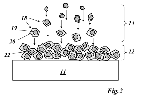
Fig. 2 shows the creation of a coating layer with an internal
oxide
network by in-flight oxidation of sprayed sub-micron powder
particles according to an embodiment of the invention;
Fig. 3 shows ¨ similar to Fig. 2 ¨ the embedding of micron
particles or
agglomerates in said sub-micron powder particle oxide network;
and
Fig. 4 shows schematically a graded coating layer in accordance
with an
embodiment of the invention.
DETAILED DESCRIPTION OF DIFFERENT EMBODIMENTS OF THE
INVENTION
The present invention discloses a specific type of sub-micron structured
coating.
Due to a sub-micron scale oxide network and fine grain microstructure, the
invention aims to reduce the LCF/TMF cracking.
Another aspect of the invention is the retardant effect for the oxidation and
the
corrosion. Due to the nano-scale oxide network of the bond coat/overlay
coating,
the impact by oxidation and corrosion is slowed down.
In consequence, the invention should enable a longer service life and/or
assure
reconditionability with less scrap parts and/or decreased operation risks,
such as
crack formation in critical area of the component due to mechanical/thermal
load,
and/or oxidation/corrosion and/or FOD (Foreign Objects Damage) events.
CA 02864618 2014-08-14
WO 2013/131874
PCT/EP2013/054337
8
The invention enables:
= the preservation of a sub-micron structure during application of the
coating
by thermal spraying techniques and during turbomachine operation (at least
for an extended operation period compared to the state-of-the art nano-
structured coatings);
= additional improvements of coating properties.
The novelty of the invention is the use of a sub-micron powder (at least to a
certain
percentage of the total powder mixture) and the way to process it (preparation
and
thermal spray application) to reach the mentioned improved coating properties.
The improved coating behavior is particularly based on a reduced TMF/LCF
effect
of the coating with (at least partial) sub-micron structure.
The invention is based on:
(1) The use of powder with sub-micron size or a powder containing at least a
portion of such sub-micron powder:
= either in form of agglomerates, consisting of at least a portion of such
sub-micron powder, processed by thermal spray techniques like HVOF,
LPPS or APS, for example (see Fig. 1);
= or in form of a suspension including at least a portion of such sub-micron
powder, when applied by thermal spray techniques like suspension
plasma spray (SPS).
Such powder is a metallic powder, preferably a MCrAlY with M. Ni, Co, Fe or
combinations thereof.
In-flight oxidation during spraying (see Fig. 2) has the effect of pre-
oxidizing
the sub-micron powder of the agglomerate or suspension. Pre-oxidation
can also be achieved by oxidative pre heat treatment of the powder mixture.
CA 02864618 2014-08-14
WO 2013/131874 PCT/EP2013/054337
9
When only a portion of the powder exhibits a sub-micron scale, it is
preferable to have the sub-micron particles distributed around the surface of
the micron and/or agglomerated spray powder particles.
(2) The application of the powder on a component of a turbo machine by
thermal spray methods (HVOF, LPPS, APS, SPS etc.) in order to form a (at
least partially) sub-micron structured coating with (at least a partially)
oxide
network. Air gun spray technologies can also be used. The use of pre-
oxidized spray powder is preferred. A homogeneous or a graded coating
can be applied (see the graded coating layer 12b in Fig. 4). For example,
the graded layer 12b can have an oxide content, which increases or
decreases with the distance from the surface of the base metal to the top
surface of the coating. In a different example the oxide content could have a
minimum in the middle of the coating thickness.
(3) The function of such a coating can be as bond coat, overlay coating or a
thermal barrier coating system for turbo machine components like gas
turbine blades or vanes. The coating of the invention can be used alone or
in combination with other standard coatings. The coating of the invention
can be used on newly made components or reconditioned components and
can also locally be applied for the partial (surface) repair of components.
(4) The component with such a coating, benefits during operation from:
= Oxidation protection:
Due to the presence of an oxide shell (20) around the particles, the
losses of reactive elements (for example Y, Al and C) during the thermal
spray process are reduced. In consequence, a more stable thermally
grown oxide (TOO) can be formed during service by diffusion
mechanism, slowing down the oxidation mechanism during operation
compared to conventional metallic coating systems. In parallel, the oxide
network (22) formed by the connecting oxide shells (20) allows to
CA 02864618 2014-08-14
WO 2013/131874 PCT/EP2013/054337
reduce the build-up of the depletion zone in the coating (top and
interface to the base metal) by slowing down the diffusion mechanism.
= Corrosion protection:
With the current invention, Chromium is finely dispersed in the coating.
5 This enables a faster gattering of sulfur and a slowing down of the
corresponding corrosion process(es).
= Mechanical lifetime:
The mechanical lifetime is improved compared to conventional coating
systems, due to several effects:
10 1) The improved coating oxidation properties enable to reduce the
overall coating thickness. As a consequence, the risk of crack
formation due to TMF and LCF is also reduced. This effect implies
the slowing down of formation and propagation of respective
damages, such as cracks.
2) Due to the 3D-oxide network (22), the mechanical load is more
homogeneously distributed along the oxide network, which reduces
the risks of sudden facture.
3) The depletion zone in the coating is reduced due to less
interdiffusion with the base metal and the atmosphere (environment).
In consequence, the risk of brittle phase precipitation (potential sites
for crack initiation) in the base metal/coating is reduced.
4) The oxide shell slows down the grain coarsening in the coating
microstructure and with this another root cause for crack formation.
5) When the oxide-network is disrupted due to cracking, the metallic
core of sub-micron particles can diffuse into the metallic coating
matrix. By subsequent local oxidation, potential cracks can be filled
up.
6) The metallic matrix ductility is increased due to the fine grain
structure, which is also beneficial for the overall coating lifetime.
Fig. 1 shows a typical thermal spray configuration 10, which can be used to
apply
the sub-micron powder coating layer according to the invention. The thermal
spray
CA 02864618 2014-08-14
WO 2013/131874 PCT/EP2013/054337
11
configuration 10 comprises a spray gun 13, which is supplied with the sub-
micron
powder 15, a fuel 16 and an oxidant 17. By burning the fuel 16, a flame 14 is
generated, which transports the powder particles to the surface of a component
11, thereby building the coating layer 12.
During the transport in the flame 14 the sub-micron powder particles 18
undergo a
reaction, as can be seen in Fig. 2, such that they are transformed into
particles
having a (metallic) core 19 surrounded by an oxide shell 20. Within the
coating
layer 12, those oxidized sub-micron particles build up an interconnected
structure
with a sub-micron oxide network 22.
When the powder material is a mixture of sub-micron particles 18 and micron
powder particles or agglomerates 21, as shown in Fig. 3, the resulting coating
layer 12a comprises those agglomerates or micron powder particles 21 being
surrounded by oxidized sub-micron powder particles 18.
One additional embodiment of the invention is a manufacturing process for an
improved thermal barrier coating system of highly thermally and especially
cyclically liner segment of a gas turbine by
a) providing an homogeneous metallic powder material made of
NiCrAlY type with Ni = balancing element, Cr = 25 wt%, A1=5 wt%,
Y=0.7 wt%, containing 30 wt% of pre-oxidised sub-micron powder
particles agglomerated with microsized powder particles (20-50
micron) of same chemical composition,
b) said sub-micron powder particles (<1 micron) are each surrounded
by an oxide shell (50-100 nm) and establish with their oxide shells an
at least partially interconnected 3D sub-micron oxide network in the
final coating layer application,
c) applying said powder material to the surface of the vane by means of
High Velocity Oxygen Fuel (HVOF) spraying technique to build up a
homogeneous bondcoating layer with a thickness of 250 micron, and
CA 02864618 2014-08-14
WO 2013/131874 PCT/EP2013/054337
12
d) the bondcoat layer is subsequently over coated with a ceramic
thermal barrier coating (300-600 micron).
The result is a bondcoat / thermal barrier coating system with improved TMF
and
oxidation resistance with the capability of forming stable TOO scales, leading
to an
improved overall coating lifetime.
A further embodiment of the invention is a manufacturing process for a graded
metallic overlay coating system of highly thermally and especially cyclically
loaded
turbine vane of a gas turbine by
a) providing a first homogeneous metallic powder material and a
second homogeneous metallic powder material, each of them have a
chemical composition of NiCrAlY type with Ni = balancing element,
Cr = 26 wt%, A1=6 wt%, Y=0.8 wt%,
b) wherein the first powder blend contains 25 wt% of pre-oxidised sub-
micron (<1 micron; 50-100 nm oxide shell) powder particles
agglomerated (average 80 micron) with microsized powder particles
(20-50 micron) of same chemical composition,
c) and wherein the second powder containing microsize powder
particles (20-50 micron),
d) applying the first powder material to the surface of the liner segment
by means of High Velocity Oxygen Fuel (HVOF) spraying technique
to build up a homogeneous first coating layer with a thickness 80
micron,
e) applying the second powder material to the surface of the first
coating layer by means of High Velocity Oxygen Fuel (HVOF)
spraying technique (250 micron),
f) applying another layer of first powder material on top of the second
layer by means of High Velocity Oxygen Fuel (HVOF) spraying
technique (80 micron),
g) the first and third layer contains each at least a partially inter-
connected 3D submicron oxide network.
CA 02864618 2014-08-14
WO 2013/131874 PCT/EP2013/054337
13
The result is a graded metallic overlay coating system with improved TMF and
oxidation resistance, leading to an improved overall coating lifetime.
In general, the initiation and propagation of damages within coatings
exhibiting an
at least partial sub-micron scale structure is retarded compared to
conventional
coating microstructures. The "sub-micron effect" is retained over extended
lifetime
periods, also due to the (at least partial) oxide network. Such aspects of the
invention give to the coating a so-called self healing characteristic.
Therefore the following advantage are reached with the invention:
Longer service life and/or reduced amount of scrap parts during reconditioning
and/or reduced operation risks and/or cost reduction related to crack
restoration,
oxidation and corrosion damage. In addition, the fine grain sized coating
allows a
diffusion heat treatment with a reduced number of heat treatment cycles. A
nano
coating as top layer improves the TMF and oxidation resistance, which results
in
an improved overall coating lifetime.
LIST OF REFERENCE NUMERALS
10 thermal spray configuration
11 component
12,12a,12b coating layer (e.g. bond coat)
13 spray gun
14 flame
15 powder
16 fuel (e.g. gaseous)
17 oxidant
18 sub-micron powder particle
19 metallic core
20 oxide shell
21 agglomerated or micron powder particle
22 oxide network (sub-micron)