Note: Descriptions are shown in the official language in which they were submitted.
TOE CONNECTOR BETWEEN PRODUCER AND INJECTOR WELLS
STATEMENT REGARDING FEDERALLY SPONSORED RESEARCH
[0001] None.
FIELD OF THE INVENTION
[0002] This invention relates to improving steam assisted gravity drainage
("SAGD") oil
production, reducing SAGD start-up time and costs, and improving overall SAGD
performance.
BACKGROUND OF THE INVENTION
[0003] Enhanced Oil Recovery (abbreviated "EOR") is a term for those
techniques for
increasing the amount of hydrocarbon that can be extracted from a reservoir.
Enhanced oil
recovery is also called improved oil recovery or tertiary recovery (as opposed
to primary and
secondary recovery). Using EOR, 30 to 60 percent or more of the reservoir's
original oil can be
extracted, compared with 20 to 40 percent using primary and secondary
recovery.
[0004] SAGD is the most extensively used FOR for in situ development of
the million plus
centipoises bitumen resources in the McMurray Formation in the Alberta Oil
Sands (Butler,
1991).
[0005] A typical SAGD process uses two horizontal wells with one above
the other, where
the upper one is the steam injector and the lower one is the producer,
although steam can be
injected into both wells in the startup phase.
[0006] The injection well is located directly above the production well,
usually a short
distance (5 to less than 10 meters). When steam is injected continuously into
the injection well, it
rises in the formation and forms a steam chamber. With continuous steam
injection, the steam
chamber continues to grow upward and laterally into the surrounding formation.
At the interface
between steam chamber and cold oil, steam condenses and the heat is
transferred to the
surrounding oil. The heated oil becomes mobile and drains together with
condensed water to the
horizontal producer due to gravity segregation within the steam vapor and
liquid (heated)
bitumen and steam condensate chamber.
1
CA 2864646 2018-06-04
[0007] The SAGD technique has many advantages when compared to
conventional steam
injection methods. In conventional steam injection, oil is displaced to a cold
area where its
viscosity increases and then the mobility is reduced. SAGD employs gravity as
the driving force
and the heated oil remains warm and movable when flowing toward the production
well.
[0008] The performance of the SAGD process is determined by many factors
including
steam chamber development, the length, spacing and location of the two
horizontal wells, heat
transfer, ability to effect steam trap control to prevent inefficient
production of live steam, heat
loss and reservoir properties. Many studies have been done to study those
elements that are
important for the success of SAGD.
[0009] As shown in FIG. 1, the standard SAGD well design employs 800 to
1000 meter
slotted liners with tubing strings landed near the toe and near the heel in
both an injector 101 and
a producer 102 to provide two points of flow distribution control in each
well, as illustrated in
FIG. 1. Steam is injected into both tubing strings at rates controlled so as
to place more or less
steam at each end of the completion to achieve better overall steam
distribution along the
horizontal injector completion.
[0010] Likewise, the producer is initially gas-lilted through both tubing
strings at rates
controlled to provide better inflow distribution along the completion. If
steam was injected only
at the heel of the injector, and water and bitumen were produced only from the
heel of the
producer, the tendency would be for the steam chamber to develop only near the
heel. This
would result in limited rates and poor steam chamber development over much of
the horizontal
completion.
[0011] Typically, SAGD wells are drilled about 5 meters apart vertically
to achieve steam
trap control whereby a gas (steam vapor)-liquid interface is maintained above
the producing well
to prevent short-circuiting of steam (e.g., premature breakthrough to the
producing well) and
undue stress on the producing well sand exclusion media. In order to establish
initial
communication between the wells, it is typical to circulate steam for 3 to 5
months in each well
prior to starting SAGD operation. A 3 to 5 month startup time increases the
amount of steam,
both water and heat, required before production can begin. This added cost may
limit projects
available for SAGD production.
2
CA 2864646 2018-06-04
[0012] There is a need to develop more thermally efficient production
techniques while
increasing the economic viability of the SAGD process.
BRIEF SUMMARY OF THE DISCLOSURE
[0013] The present disclosure provides a novel process and system for
increasing the thermal
efficiency of SAGD operations. By connecting the toe end of the injection well
with the toe end
of the production well, thermal communication between the two wells is
initiated directly. Flow
directly from the injection tubing to the production tubing begins when steam
is injected, which
will significantly reduce the start-up time and cost.
[0014] In one embodiment, a single injection tube is provided to the heel
end of the injection
well liner and steam is pumped through the injection well liner to the
connection at the toe end of
the injection well to the production well liner, and finally to the heel end
of the production liner
and the production tube. This results in a reduction in materials, startup
time, startup cost, steam
oil ratio and improved production, all of which lead to capital investment
savings and make
SAGD production viable in a larger number of reservoirs.
[0015] In one embodiment, SAGD hydrocarbon production well having a
horizontal
production well is provided in a hydrocarbon reservoir. A horizontal injection
well is vertically
aligned above the horizontal production well, and the horizontal injector
tubing or horizontal
production well is provided with a hook length the well, thus fluidly
connecting both the injector
and production wells.
[0016] In some embodiments, more than one hooked length can connect the
well pairs at
more than one location along the well pairs. In other embodiments, a single
hooked length joins
the wells pairs at or near the toe ends of the wells.
[0017] In another embodiment, a process for steam assisted gravity
drainage (SAGD)
hydrocarbon production is described including installing a horizontal
production well and
horizontal injection well in a hydrocarbon reservoir; injecting steam into the
injector well; and
producing hydrocarbons from said production well, where the horizontal
injector well or
horizontal production well have a hook at the toe end of the well connecting
the injector well and
the production well.
[0018] Another embodiment provides an SAGD method, comprising:
3
CA 2864646 2018-06-04
[0019] a horizontal production well having a first toe and comprising a
production tubing
placed horizontally in a hydrocarbon reservoir; and
[0020] a horizontal injection well having a second toe and comprising an
injection tubing
vertically aligned above said horizontal production well,
[0021] wherein said first toe and said second toe are fluidly connected
with a toe connector,
thus fluidly connecting said production well and said injection well.
[0022] Preferably, the toe connector is also equipped with a flow control
device, which
allows the fluidic connection to be blocked, but other method of stopping flow
or blocking the
fluidic connection can be used, as is known in the art.
[0023] Another embodiment is an improved method of SAGD, said method
comprising
providing horizontal production well below a horizontal injection well,
injecting steam into said
injection well to mobilize hydrocarbons, and producing said mobilized
hydrocarbons from said
production well, the improvement comprising fluidly connecting toe ends of
said production well
and said injection well with a toe connector, wherein said toe connector
comprises an optional
flow control device.
[0024] Preferably, SAGD wells are in hydrocarbon reservoirs of heavy oil,
bitumen, tar
sands, asphaltenes, or combinations thereof, because SAGD is particularly
beneficial for heavier
oils. However, the use is not necessarily limited thereby and can be use for
other hydrocarbons.
[0025] In one embodiment, SAGD hydrocarbon production is shut in for
startup for between
1 and 30 days, including 1 day, 2 days, 3 days, 4 days, 5 days, 6 days, 7
days, 8 days, 9 days, 10
days, 11 days, 12 days, 13 days, 14 days, 15 days, 16 days, 17 days, 18 days,
19 days, 20 days,
21 days, 22 days, 23 days, 24 days, 25 days, 26 days, 27 days, 28 days, 29
days and 30 days. In
yet another embodiment, steam injection and heavy oil production occur without
a startup
period.
[0026] As used herein, the term "SAGD" includes steam heating and gravity
drainage
production methods, even where combined with other techniques such as solvent
assisted
production methods, EM heating methods, cyclic methods and the like.
[0027] By "providing" herein we do not mean to imply contemporaneous
drilling, and
existing wells and liners can be used, if the toe connector can be added
thereto to connect the two
4
CA 2864646 2018-06-04
wells. However, in some cases, well drilling may be required at least at the
toe ends to add the
toe connector.
[0028] By "toe" herein, what is meant is the end or near end of a
horizontal well, farthest
from the vertical portion. In contrast, the horizontal portion closest the
vertical portion is the
"heel."
[0029] As used herein a "hooked length" is a deviation in a horizontal
well path, towards the
companion well, such that the two wells will eventually be in fluid
communication. The term
"toe hook" refers to such as hooked length at or near the toe of the well.
[0030] By "toe connector" herein what is meant is a fluidic connection
between the toe of the
.. injection well and the toe of the producer well. The shape can vary,
depending on how the
connection is achieved, as shown in FIG. 3-5.
[0031] The use of the word "a" or "an" when used in conjunction with the
term "comprising"
in the claims or the specification means one or more than one, unless the
context dictates
otherwise.
[0032] The term "about" means the stated value plus or minus the margin of
error of
measurement or plus or minus 10% if no method of measurement is indicated.
[0033] The use of the term "or" in the claims is used to mean "and/or"
unless explicitly
indicated to refer to alternatives only or if the alternatives are mutually
exclusive.
[0034] The terms "comprise", "have", "include" and "contain" (and their
variants) are open-
.. ended linking verbs and allow the addition of other elements when used in a
claim.
[0035] The phrase "consisting of" is closed, and excludes all additional
elements.
[0036] The phrase "consisting essentially of' excludes additional
material elements, but
allows the inclusions of non-material elements that do not substantially
change the nature of the
invention, such as instructions for use, adding a solvent or other EOR
techniques to the inventive
methods, systems and the like.
5
CA 2864646 2018-06-04
BRIEF DESCRIPTION OF THE DRAWINGS
[0037] A more complete understanding of the present invention and
benefits thereof may be
acquired by referring to the follow description taken in conjunction with the
accompanying
drawings in which:
[0038] FIG. 1: Typical prior art SAGD completion with toe and heel tubing
in both the steam
injection liner and the producing liner.
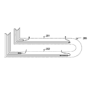
[0039] FIG. 2: SAGD completion with a snorkel or toe connector connecting
the toe end of
the injection liner with the toe end of the production liner, according to one
embodiment of the
invention.
[0040] FIG. 3: A SAGD configuration with production toe hooked and
connected to the
injection well, according to one embodiment of the invention.
[0041] FIG. 4: A SAGD configuration with injection toe hooked and
connected to the
production well, according to one embodiment of the invention.
[0042] FIG. 5: A SAGD configuration with the injection and production toe
ends both
hooked and connected together, according to one embodiment of the invention.
DETAILED DESCRIPTION
[0043] Turning now to the detailed description of the preferred
arrangement or arrangements
of the present disclosure, it should be understood that the features and
concepts of this disclosure
may be manifested in other arrangements and that the scope of the invention is
not limited to the
embodiments described or illustrated. The scope of the invention is intended
only to be limited
by the scope of the claims that follow.
[0044] FIG. 2 illustrates an injection well 201 that injects steam,
possibly mixed with
solvents or other fluids, and a production well 202 that collects heated crude
oil or bitumen that
flows out of the formation, along with any water from the condensation of
injected steam.
[0045] As used herein SAGD refers to such a thermal hydrocarbon production
process where
two parallel horizontal oil wells are drilled in the formation, one about 0.5
to <10 meters above
the othcr. In some embodiments, the injection and production wells 201, 202
may be between
0.5 and 3, including 1, 1.5, 2, 2.5 or 3 meters apart.
6
CA 2864646 2018-06-04
[0046] The vertical distance between the injection well and the
production well is crucial in
the SAGD operations. Typically a magnetic guidance tool (MGT, not shown) is
placed inside
the production well, which is drilled first, for directional ranging. The MGT
moves slightly
ahead of the drilling assembly for drilling the injection well, while emitting
an electromagnetic
field that is picked up by the drilling assembly for the injection well such
that an accurate
distance between the injection and production wells can be maintained.
[0047] A toe hook 205 or 'snorkel' is an intentional connection at the
toe end of the injection
and production wells 201, 202 that provides a fluid connection directly
between the injection
well 201 and the production well 202 upon startup. The toe hook 205 may be
present in the
injection well 201, production well 202 or both injection and production wells
201, 202.
[0048] In one embodiment, the toe hook 205 is completed within the
hydrocarbon reservoir.
In another embodiment, the toe hook 205 is completed beyond the productive
reservoir. In yet
another embodiment, the toe hook 205 may be an open hole or side lateral
extending away from
the wellbore liner.
[0049] In another embodiment, the toe hook 205 may contain a screen, valve
or other device
that can be left open, or may provide support for cement, packing or another
device for
selectively closing the connection between the injection and production wells
201, 202.
100501 As used herein, a hydrocarbon may include any petroleum reservoir
including
conventional oils, heavy oil, bitumen, tar sands, asphaltenes, and the like.
Preferably, SAGD is
used with high viscosity oils, tars or bitumens that require heating to
liquefy or produce the
hydrocarbon. In some instances, SAGD may be used with other hydrocarbon
reservoirs as an
enhanced oil recovery technique or to produce additional hydrocarbons from a
reservoir. In one
embodiment, SAUD is used to produce bitumen from a subterranean reservoir.
[0051] As discussed above, standard SAGD is a thermal in-situ heavy oil
recovery process.
The procedure is applied to at least a well pair, but multiple wells are often
used. The well pairs
are first drilled vertically, then slowly angled, typically 9 /100 feet until
finally drilled
horizontally, parallel and vertically aligned with each other. The length of
and vertical separation
between the injection and production wells are on the order of 1 kilometer and
5 meters,
respectively.
7
CA 2864646 2018-06-04
[0052] The upper well (or wells) is known as the "injection well" and the
lower well (or
wells) is known as the "production well". The process herein begins by
circulating steam in both
wells, preferably through the hooked length toe connector discussed here, so
that the bitumen
between the well pair is more efficiently heated enough to flow to the lower
production well. The
steam chamber heats and drains more and more bitumen until it has overtaken
the oil-bearing
pores between the well pair.
[0053] Steam circulation in the production well is then stopped and steam
injected into the
upper injection well only, so that the bitumen located above the injection
well can also be heated
and viscosity reduced and eventually produced through the production well.
Specifically, the
cone shaped steam chamber, anchored at the production well, now begins to
develop upwards
from the injection well. As new bitumen surfaces are heated, the oil lowers in
viscosity and flows
downward along the steam chamber boundary into the production well by way of
gravity.
[0054] The following is a discussion of certain embodiments of the
invention. Each is
provided by way of explanation of the invention, one of many embodiments of
the invention, and
should not be read to limit, or define, the scope of the invention.
PRODUCTION TOE CONNECTED TO INJECTION WELL
[0055] FIG. 3 shows the horizontal production well 202 drilled using
standard drilling
techniques. A toe tip 305 of the production well 202 is deviated upward
forming a
communication channel, like a snorkel.
[0056] The exact shape of the communication channel is not limited, as long
as thermal
communication through the steam can be effectively carried out and the
drilling cost is kept to
the minimum. The drilling assembly is pulled back to the kickoff point of the
snorkel and the
horizontal section is extended to the design length of the completion. The
hole is cleaned as
normal and a producer liner 304 is run in the horizontal section past the
snorkel (not into the
snorkel).
[0057] Then, the injection well 201 is drilled above the production well
202 as normal with
the intention that the tip of the injection well 201 will intersect the
snorkel or pass very close to
the snorkel. Then, an injector liner 303 is run in the injection well 201.
Although the injection
8
CA 2864646 2018-06-04
well 201 may be drilled first, this is not standard practice and has many
limitations. For example,
it is difficult to maintain the vertical distance if the injection well 201 is
drilled first.
[0058] In one
embodiment, the toe tip 305 of the production well 202 is deviated upward
approximately 7 vertical meters over less than 50 m of horizontal distance.
Tighter turn radii may
be used but are not required.
[0059]
Alternatively, the toe tip 305 of the production well 202 may be slowly raised
beyond
the production zone and the injection well 201 extended to intersect with the
production well
202. The slope of the hook or snorkel may be anywhere from 7:50 as described
above or 1:10,
1:7, 1:5, 1:4 or 1:3 vertical incline for each linear meter. It is to be noted
that the slope of the
snorkel should not affect the efficiency of thermal communication between the
injection and
production wells, but rather a practical result of choosing different drilling
parameters.
INJECTION TOE CONNECTED TO PRODUCTION WELL
[0060] FIG. 4
illustrates the production well 202 drilled and completed first, near the
bottom
of the reservoir. Next, the injection well 201 is drilled above and parallel
to the production well
202 as discussed above, but a toe tip 405 of the injection well 201 is
"dipped" downward to
connect with the production well 202 without damaging the producer liner 304.
The injector
liner 303 may now bc run in the injection well 201.
[0061] In one
embodiment, the injector liner 303 may employ blank pipe (not slotted) for the
toe tip 405 portion except for an open screen portion at the end close to the
production well 202.
This blank section may be plugged later by a ball, plug or other suitable
means when appropriate.
[0062] The
optional blank liner may also incorporate other devices including a valve,
screen,
shut-off mechanism or flow control device 406. Although the injection well 201
may be drilled
first, this is not standard practice and has many limitations. It is easier to
detet mine if the hook is
progressing correctly if the production well 202 is drilled first and the
injection well 201 is
dropped close to the production well 202.
HOOKING BOTH THE INJECTION AND PRODUCTION WELL
[0063] FIG. 5
shows hooking both the injection and production wells 201, 202 with either
the injection or production well drilled first. Typically, the production well
202 is drilled first
and the injection well 201 drilled over and parallel to the production well
202. This
9
CA 2864646 2018-06-04
accommodates curves and undulation in the formation underburden. The
production well 202 is
drilled to length and hooked slightly upward at the end 507 of the well to a
fixed location. The
injection well 201 is drilled to a fixed distance over the production well
202.
[0064] Once the injection well 201 is drilled to length it is hooked at
the end 505 of the
injection well 201 such that the injection and production wells meet at a
fixed location within the
formation.
[0065] The point where the injection and production wells 201, 202 meet
may be treated
with a flowable proppant 506, screen, or liners such that once the steam
chamber is sufficiently
formed, the toe of the well may optionally be sealed or closed. This optional
procedure is not
required because the steam trap will typically rise above the production well
202.
100661 SAGD injection, production or both injection and production wells
may be hooked
toward one or the other to connect the wells at the toe end of the well.
Whatever drilling method
employed, the resulting toes are now fluidly connected via a "toe connector."
[0067] The toe connector may be added during an initial completion,
during well work-over,
or when the initial wells are extended. For some wells, it may help to improve
initial startup or
reduce startup time to zero. Initial production with a toe-to-toe connection
can begin
immediately because breakthrough is not required.
[0068] Steam may be injected through either well if startup is required.
[0069] In one embodiment, steam is injected through the injection well
and returned through
the production well. Because this is the same configuration used during
standard SAGD
production, no additional equipment, start-up equipment or changes to
configuration are
required. Because startup time is reduced or entirely removed, costs and
steam/water to oil ratios
are reduced to a minimum. This is extremely cost effective and conserves
resources, useful
when water and other materials are scarce or difficult to bring to the site.
[0070] Although the systems and processes described herein have been
described in detail, it
should be understood that various changes, substitutions, and alterations can
be made without
departing from the spirit and scope of the invention as defined by the
following claims. Those
skilled in the art may be able to study the preferred embodiments and identify
other ways to
practice the invention that are not exactly as described herein. It is the
intent of the inventors
CA 2864646 2018-06-04
that variations and equivalents of the invention are within the scope of the
claims while the
description, abstract and drawings are not to be used to limit the scope of
the invention. The
invention is specifically intended to be as broad as the claims below and
their equivalents.
[0071] The discussion of any reference is not an admission that it is
prior art to the present
invention, especially any reference that may have a publication data after the
priority date of this
application. References are listed again here for convenience:
[0072] US6158510, Bacon, et al., "Steam distribution and production of
hydrocarbons in a
horizontal well." ExxonMobil Upstream Res Co., (2000).
[0073] US6119776, Graham, et al., "Methods of stimulating and producing
multiple
stratified reservoirs," Halliburton, (2000).
[0074] US7559375, US20080217001, Dybevik, et at., "Flow control device
for choking
inflowing fluids in a well," Reslink AS, (2008).
[0075] US2010126727, Vinegar, et al., "In Situ Recovery From A
Hydrocarbon Containing
Formation," Shell (2010).
[0076] US20110114388, Lee, et al., "Methods and apparatus for drilling,
completing and
configuring U-tube boreholes," Halliburton Energy Services, (2011).
[0077] Akin and Bagci, "A laboratory study of single-well steam-assisted
gravity drainage
process," J. Petroleum Sci. Eng. 32:23¨ 33 (2001).
[0078] Butler, "Thermal Recovery of Oil & Bitumen", Chapter 7: "Steam-
Assisted Gravity
Drainage", Prentice Hall, (1991).
[0079] Elliot and Kovscek, "A Numerical Analysis of the Single-Well Steam
Assisted
Gravity Drainage Process (SW-SAGD)"
[0080] Pao, Richard H. F., "Fluid Mechanics", pp. 286-290. John Wiley &
Sons, 1965.
[0081] Stalder, "Test of SAGD Flow Distribution Control Liner System,
Surmont Field,
Alberta, Canada." J. Canadian Petroleum Tech., IN PROCESS.
100821 What is claimed is:
11
CA 2864646 2018-06-04