Note: Descriptions are shown in the official language in which they were submitted.
CA 02864921 2014-08-18
WO 2013/126709 PCT/US2013/027331
INTERNATIONAL APPLICATION
FOR
ADVANCED THERMAL CONDUCTIVE HEATER SYSTEM FOR
ENVIRONMENTAL REMEDIATION AND THE DESTRUCTION OF
POLLUTANTS
BY GRANT GECKELER
FIELD OF THE INVENTION
[000i] This invention is directed to an improved method for the remediation of
subsurface soil and/or groundwater containing pollutants. This method may be
conducted both in-situ and ex-situ.
BACKGROUND OF THE INVENTION
[0002] Pollutants in soil, groundwater, or other affected media pose a risk to
human
health. Many pollutants are carcinogenic, having maximum screening levels
promulgated by government bodies. Common pollutants include volatile organic
compound, semi volatile organic compound, polycyclic aromatic hydrocarbons,
pesticides, herbicides, tars, polychlorinated biphenyls, mercury, dioxins,
residue of
explosives, and heavy hydrocarbons.
[00 03] Pollutant spills and leakages into the earth due to corroded or
defective
containers or pipelines is a common pathway for pollutants to enter the soil
and/or
groundwater. The hydrocarbons. A plethora of techniques have developed in
prior art
for the remediation soils and groundwater contaminated by pollutants.
Generally, the physical/chemical properties of the pollutant, and the nature
of the
contaminated media govern the remediation technique selected. Accordingly, if
pollutants are reasonably mobile and difficult to degrade (e.g., chlorinated
solvents),
and the soil is highly permeable, then soil vapor extraction (SVE) techniques,
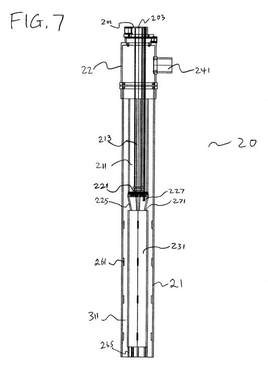
which
develop a vacuum gradient in the soil, would prove effective. Semi-volatile
pollutants
(e.g., Pentachlorophenol) do not readily volatize, so soil vapor extraction is
not an
effective technique. Alternative techniques have been considered in prior are.
Many of
1
CA 02864921 2014-08-18
WO 2013/126709 PCT/US2013/027331
the proposed techniques involve the excavation of the contaminated areas and
subsequent incineration of the soil (e.g., direct or indirect ex-situ thermal
desorption).
Such techniques, while effective in decontaminating the affected soil, are
cost
prohibitive and energy intensive.
[0004] Other prior art techniques involve the use of radio frequency energy,
conduction heaters or electric heater wells in combination with vapor
extraction
systems. For example, U.S. Pat. No. 4,670,634 discloses a method for in-situ
decontamination of spills and landfills by radio frequency heating. The soil
is heated by
radio frequency energy to a temperature higher than that promotes dielectric
heating.
The heating allows elevated temperatures in the range of 100 C. to 400 C.
Decontamination of the heated soil may occur in a number of ways, as by
pyrolysis,
thermally assisted decomposition, distillation, or reaction with a reagent,
such as
oxygen. However, this method uses radio frequency power that results in non-
uniform
heating of the soil resulting in cyclical hot and cold spots in the soil. This
method also
requires burdensome vapor collection and electromagnetic protective barriers
at the
surface, resulting in high operating expenses.
[0005] U.S. Pat. No. 5,190,405 discloses an in situ method for removal of
pollutants
from soil by vapor extraction through perforated vertical heater wells
inserted in the
soil. The vertical heater wells to heat the soil to elevated temperatures by
thermal
conduction are used with sheeting on the soil surface to reduce the short-
circuiting
effects of vapor extraction. Soil contaminants are removed by vaporization, in-
situ
thermal decomposition, oxidation, combustion, and by steam stripping.
[0006] U.S. Pat. No. 5,114,497 discloses a method of remediation comprising
supplying
thermal energy to the soil at one or more locations under the surface of the
soil through
a relatively flat and flexible heat source located between the surface of the
soil and an
insulative cover material. The vapors resulting from contaminant vaporization
or
decomposition under the influence of thermal energy are then collected under
the
influence of reduced pressure.
[0007] U.S. Patent No. 5,169,263 discloses a similar in-situ heating process
which
utilizes an in-situ vapor recovery system comprising perforated or slotted
pipes buried
2
CA 02864921 2014-08-18
WO 2013/126709 PCT/US2013/027331
in the soil below the depth of contamination. A vapor extraction and treatment
system is
connected to the pipes, and heat is supplied to the soil surface by a
relatively flat and
flexible resistance heater.
[0008] U.S. Pat. No. 5,193,934 discloses another in-situ desorption system
which
utilizes a perforated or slotted pipe buried in the soil below the depth of
contamination
in the soil, with a vapor extraction and treatment system. The source of
heating
comprises of fuel and compressed air fed to a pressurized combustion chamber
(located
on the surface of the earth) and combusted, the combustion products flow into
the in-
situ pipe and distributed through the contaminated soil. The contaminants and
their
by-products are displaced by the combustion products into the vapor treatment
system.
[0009] U.S. Pat. No. 5,011,329 discloses an in-situ method and apparatus for
injecting
hot gas into boreholes formed in a polluted soil area to vaporize the soil and
pollutants,
and for collecting the resultant off gas of pollutants above ground. A burner
heats
pressurized gases and mixes the same with combustion gases for delivery into
the
polluted soil via in-situ injection.
[ooio] European Patent Applications EP10447027 and EP10447028 and U.S. Pat.
No.
7,618,215 disclose methods and apparatuses for soil remediation using heater
composed
of a gas burner having its burner nozzle and burner end located above the
surface of the
ground and polluted zone, said burner nozzle and burner end placed in a tube
portion
that extends into the ground and polluted zone. The hot combusted gases are
forced
down the entirety of the tube portion, transferring heat by conduction
vertically down
the tube, first at the tube's upper portion and finally reaching the tube's
lower portion.
An extraction tube transfers off gases to the gas burner, where they are
combusted as
supplemental fuel. Means of re-using heat energy from the primary heater in a
separate, second heater are disclosed.
[ooli] While the stated methods, apparatuses and techniques may prove
effective in
providing in-situ decontamination of the soil in certain and limited
situations, these
methods, apparatuses and techniques generally necessitate costly operating and
energy
inputs, require expensive equipment, provide inefficient heat transfer to
pollutants or
soil, or require elaborate vapor extraction and treatment systems.
3
CA 02864921 2014-08-18
WO 2013/126709 PCT/US2013/027331
[0012] The need exists for a cost-effective, improved and efficient in-situ
technique for
the removal of pollutants from the subsurface soil and groundwater. A more
energy
efficient technique of delivering heat to the polluted soil and groundwater is
needed,
such that the pollutants are quickly and effectively mobilized and removed.
Also, the
use of propane or natural gas to produce the heat of combustion is needed at
sites where
large supplies of electricity are not readily available. Just as importantly,
the delivery of
that heat to the polluted zone in a manner that minimizes heat loss in
unpolluted zones
is needed. To minimize equipment requirements, a technique that oxidizes
extracted
pollutant off gas in one or several heaters is needed.
[0013] A thermal conductive heating and desorption system is disclosed,
providing
superior results to other systems for the removal of pollutants from soil,
groundwater
and other affected medias using a novel enhanced gas fired recuperative heater
and
oxidation system. Pollutants in the affected, heated media are partially
destroyed by
hydrolysis, pyrolysis and/or oxidation processes. Remaining pollutants are
extracted
from the affected media, and pollutant off gas is then introduced into the
heater system
where it is both thermally and catalytically oxidized. Heat from combusted
fuel and
pollutant off gas in the heater system is used to preheat incoming combustion
air
through a recuperative heat exchanger, enabling significant reductions in fuel
usage by
the heater system. Combusted fuel and off gas discharged from the heater
system may
be further treated to achieve specified discharge standards.
SUMMARY
[0014] Methods of accomplishing the same are similarly provided, for
efficiently
remediating polluted media by optimizing thermal conductive heating
temperatures and
off gas extraction rates and treatment to achieve compliance with changing
environmental regulations. According to a feature of the present disclosure, a
system
for thermally treating affected media is disclosed comprising, in combination:
a gas
fired heater having both an inner and outer passage, a burner module having a
recuperative heat exchanger, an exhaust passage, a catalytic surface area, a
differential
pressure source, and an off gas extraction point.
4
CA 02864921 2014-08-18
WO 2013/126709 PCT/US2013/027331
[0015] According to another feature, a burner module is disclosed comprising,
in
combination: a differential pressure source, a gas inlet, a gas passage, a
combustion air
inlet, a combustion air passage, a combustion air/gas mixer, a burner nozzle,
an igniter,
a combusted gas passage, and an exhaust outlet.
[oo16] According to another feature, the heater is placed vertically,
horizontally or at a
slant angle into polluted soil. Gas and combustion air are supplied to the
burner module
and are carried via their respective passages to the combustion air/gas mixer
where the
gas and combustion air are mixed to produce a flame that is directed through
the burner
nozzle and further down the inner passage (combusted gas passage). Combusted
gases
discharged from the bottom end of the heater's inner passage strike the closed
end of the
outer passage and flow reversely through the outer passage (exhaust passage)
in order to
further transfer heat uniformly through the heater, and to preheat the
combustion air
flowing toward the burner end. Combusted gases remain enclosed in the heater.
Combusted air exits the heater through the burner's exhaust passage and
exhaust outlet.
Heat produced by the heater is transferred by means of conduction, radiation,
convection and advection to the polluted media.
[0017] Further, off gas may be extracted from one or several points from the
polluted
media, such as through soil vapor extraction or multi-phase extraction wells.
One or
more differential pressure sources may apply vacuum to these off gas
extraction points,
and the extracted off gas is then directed to the burner through the
combustion air inlet.
The off gas is both thermally and catalytically oxidized within the heater
system. First,
the burner thermally oxidizes this incoming off gas at the burner end and
further
thermal oxidation occurs in the heater due to the heater's features enabling
increased
residency time. Second, a catalytic surface area in the outer passage of the
heater reacts
with any remaining pollutants in the off gas to further catalytically oxidize
said
pollutants. Alternatively, pollutant off gases that are problematic to destroy
via
oxidation (i.e., chlorinated solvents), may be directed instead to an
aboveground vapor
treatment module (i.e., granular activated carbon or condensation treatment).
[oo18] As used in the present disclosure, the term "off gas" shall be defined
as gasses
extracted from at least one source of off gas, including but not limited to
vapors to-be-
removed during the course of soil or groundwater remediation activities and
byproduct
CA 02864921 2014-08-18
WO 2013/126709 PCT/US2013/027331
gases from the decomposition of pollutants. As used in the present disclosure,
the term
"pollutant" shall be defined as any volatile organic compound, semi volatile
organic
compound, polycyclic aromatic hydrocarbons, pesticides, herbicides, tars,
polychlorinated biphenyls, mercury, dioxins, residue of explosives, heavy
hydrocarbons,
and other pollutants as known to artisans. As used in the present disclosure,
"soil vapor
extraction" (SVE), also known as soil venting or vacuum extraction, is a
method that
applied a vacuum to one or more extraction points near the source of
pollutant(s) in the
soil. Volatile constituents of the contaminant mass evaporate and the vapors
are drawn
toward and extracted through the extraction points.
[0019] Prior technologies often rely on the use of electrical inputs for the
heating of
soils, groundwater and affected media via thermal conduction. Artisans will
appreciate
the features of the present disclosure that are tailored to reduce energy
consumption
compared to the prior art. Propane or natural gas is the primary source of
energy for the
heaters. Propane and natural gas are generally considered "clean energy"
sources, and
as such, do not require the purchase of carbon credits or clean energy credits
to meet the
clean energy goals set forth by the United States Environmental Protection
Agency and
other regulatory bodies. The use of the recuperative heat exchanger in the
present
disclosure efficiently preheats air to-be-combusted, thereby reducing the
energy input
required to attain a given combusted gas temperature, and further reducing
byproduct
gas emissions.
[0020] Prior technologies also rely on the combustion of fuel/gas and air at a
location
above the level of the ground or above the zone of pollutants to be
remediated. Such an
approach requires an additional energy to both transfer the heat of combustion
to the
desired treatment zone and to compensate for heat loss into undesired zones
(i.e. the
top portions of the heating device). Artisans will appreciate the present
disclosure's
placement of the burner's mixer/nozzle nearer to, or in, the desired treatment
zone.
Artisans will similarly appreciate that the upwardly mobile convective heat
from
combustion is utilized to preheat the combustion air traveling downward
through the
heater's recuperative heat exchange system.
6
CA 02864921 2014-08-18
WO 2013/126709 PCT/US2013/027331
BRIEF DESCRIPTION OF THE DRAWINGS
[0021] FIG. 1 is an illustration of an embodiment of a soil and groundwater
remediation system according to the present invention.
[0022] FIG. 2 is an illustration of another embodiment of a soil and
groundwater
remediation system according to the present invention.
[0023] FIG. 3 is an illustration of another embodiment of a soil and
groundwater
remediation system according to the present invention.
[0024] FIG. 4 is a two-dimensional cross-sectional view of an embodiment of an
advanced thermal conductive heater system that is used in a soil and
groundwater
remediation system according to the present invention.
[0025] FIG. 5 is a three-dimensional cross-sectional view of an embodiment of
an
advanced thermal conductive heater system that is used in a soil and
groundwater
remediation system according to the present invention.
[0026] FIG. 6 is another two-dimensional cross-sectional view of an embodiment
of an
advanced thermal conductive heater system that is used in a soil and
groundwater
remediation system according to the present invention.
[0027] FIG. 7 is a two-dimensional cross-sectional view of another embodiment
of an
advanced thermal conductive heater system that is used in a soil and
groundwater
remediation system according to the present invention.
[0028] FIG. 8 is a three-dimensional cross-sectional view of the same
embodiment of
an advanced thermal conductive heater system that is used in a soil and
groundwater
remediation system according to the present invention.
[0029] FIG. 9 is another two-dimensional cross-sectional view the same
embodiment
of an advanced thermal conductive heater system that is used in a soil and
groundwater
remediation system according to the present invention.
[0030] FIG. 10 is a top-looking view of an embodiment of a complimentary
pattern of
heater wells and extraction wells that is used in a soil and groundwater
remediation
system according to the present invention.
7
CA 02864921 2014-08-18
WO 2013/126709 PCT/US2013/027331
[0031] FIG. 11 is a top-looking view of an embodiment of a hexagonal pattern
of heater
wells and extraction wells that is used in a soil and groundwater remediation
system
according to the present invention.
DESCRIPTION OF THE PREFERRED EMBODIMENT
[0032] FIGS. 1, 2 and 3 show a generalized schematic of the invention.
Briefly, in the
disclosed apparatus and method pollutants are thermally desorbed from the
polluted
soil zone by direct heating of the polluted soil and/or groundwater zone. The
heat is
generated by combustion of fuel with air within a heater placed at or near the
polluted
zone. Traditional soil vapor extraction wells or techniques may be utilized to
collect the
off gas generated as a result of the heating of the polluted zone. Off gases
may be
directed to the heater for thermal and catalytic oxidization or sent to a
traditional off gas
treatment system.
[0033] The apparatus of the claimed invention is schematically depicted in
FIGS. 1, 2
and 3. The basic components of this invention are: (1) a heater well 20
containing a
heater tube module 21 and burner module 22; (2) off gas barriers 50 which
enclose the
surface of the soil or polluted zone 52 and which prevent the vertical flow of
heat and
vaporized off gases from polluted zone 52 and also prevents air flow into the
polluted
zone 52 from the atmosphere 70 through the soil surface 62; (3) extraction
wells 80, (4)
off gas extraction and treatment module loo, and (5) natural gas, propane or
other fuel
(e.g., methane) supply and air or other oxygen supply is connected by lines
120 and 121,
respectively, to the burner module 22.
[0034] Turning to FIGS. 1, 2 and 3, and focusing on heater well 20, the
exterior region
around it which borders the unpolluted zone 51 is packed or filled with a
material with
relatively poor heat conduction properties, such as refractory cement or
mortar. The
exterior region around heater well 20 which borders the polluted zone 52 is
packed or
filled with a material with relatively good heat conduction properties, such
as soil mixed
with steel shot or bauxite. The exact fill materials and fill area may be any
combination
as known by artisans.
8
CA 02864921 2014-08-18
WO 2013/126709 PCT/US2013/027331
[0035] Turning to FIGS. 4, 5, 6, 7, 8 and9, air or oxygen lines 121 and fuel
or gas lines
120 are routed to the heater well 20 and connect to the burner module 22 so
that air or
oxygen enters via combustion air inlet 201 and fuel or gas enters via gas
inlet 203.
Combustion air and fuel are neither mixed nor ignited above the grade of soil
or media
into which the heater well 20 is inserted. Instead, the combustion air and
fuel travel
down the heater well 20 through their respective passages 211 and 213. A
differential
pressure source 256 produces positive pressure to force combustion air down
combustion air passage 211. Differential pressure source 256 may be fitted
with
regulators or variable drives to control the flow and pressure exerted upon
the
combustion air, as would be known to artisans. Differential pressure source
256 may be
comprised of the same equipment as off gas extraction and treatment module 100
and
vacuum module 56. Gas delivered under pressure to gas inlet 203 travels down
heater
well 20 through gas passage 213, and gas regulators and orifices may be used
to control
the flow and pressure of gas, as would be known to artisans.
[0036] Gas passage 213 terminates into combustion air/gas mixer 221, where the
gas is
released under pressure to mix with preheated combustion air at a location
just above or
within burner nozzle 225. To begin the combustion of this air/gas mixture,
igniter 227
provides a source of ignition. After a predetermined temperature is reached
inside the
heater well 20, the igniter may be turned off, and the temperature of the
preheated air
mixing the gas is sufficient to combust the mixture thoroughly. Alternating
cycles of
on/off firing, modulated firing or pulsated firing may be accomplished in
heater well 20,
as would be known to artisans.
[0037] Depending on the particular fuel and air inputs into heater module 22,
temperatures ranging from 200 to 1,200 C. may be generated within the heater
well
20 so as to develop a sufficient heat flux transfer into the polluted zone 52
surrounding
the heater well 20, causing the pollutants to be mobilized.
[0038] The combusted gases exiting burner nozzle 225 travel further downward
through combusted air passage 231. The heat of the combusted gases is
transmitted
downwardly and laterally by the processes of radiation and conduction. Some
heat is
also transferred vertically upwards. Combusted gases discharged from the
bottom
opening of the combusted air passage strike the closed, bottom end of the
heater well
9
CA 02864921 2014-08-18
WO 2013/126709 PCT/US2013/027331
20, and flow reversely (upwardly) through the heater well's exhaust passage
311 and
further transfer heat uniformly and evenly through both the heater well 20 and
the
polluted zone 52.
[0039] The flow of hot combusted gases through the exhaust passage 311
transfers
some heat (via conduction and radiation) to the walls of combustion air
passage 211,
which it contacts. This heat transfer preheats the combustion air flowing
downward
through combustion air passage 211 and cools the combusted air flowing upward
through exhaust passage 311.
[0040] Combusted air exits the heater through the burner module's exhaust
outlet 241.
Combusted air may be discharged to atmosphere, further treated to reduce
byproduct
gases if necessary, used to heat or preheat other media, or otherwise used as
known by
artisans.
[0041] In one preferred embodiment, set forth in FIGS. 4, 5 and6, combustion
air
passage 211 and combusted air passage 231 are of identical or similar outer
and inner
dimensions, and said passages are welded or otherwise affixed to form a
contiguous
passage. Stabilizers 261 are affixed to the outer portion of combustion air
passage 211
and combusted air passage 231, and stabilizers 261 fit against the outer wall
of exhaust
passage 311. Stabilizers 261 have at least two purposes: they center the
passages 211 and
2xx within heater well 20 and they transmit heat via conduction outwardly to
the
extremities of heater well 20.
[0042] In another preferred embodiment, as set forth in FIGS. 7, 8 and 9,
combustion
air passage 211 and combusted air passage 231 are of identical or similar
outer and inner
dimensions, but said passages do not form a contiguous passage, instead
forming a
recuperative aperture 271 between combustion air passage 211 and combusted air
passage 231. Combusted air passage 231 has supporting legs 265 to support its
weight
inside heater tube module 21, and allow hot combusted air to exit combusted
air passage
231 for entry into exhaust passage 311. Combusted air passage 231 also
utilizes
stabilizers 261 to center it inside heater tube module 21. Combusted air
leaving burner
nozzle 225 and combustion air passage 211 travels downward into combusted air
passage 231, effectively crossing through the plane of recuperative aperture
271. A
CA 02864921 2014-08-18
WO 2013/126709 PCT/US2013/027331
portion of hot exhaust gases traveling upwards through exhaust passage 311 are
induced
by draft and pressure forces into and through recuperative aperture 271, and
are re-
introduced to combusted air passage 231. This re-introduction of hot exhaust
gases
recuperates a portion of heat energy from the gases to-be-exhausted and
reduces the
fuel/gas and air/oxygen inputs required to achieve or maintain a given
temperature.
[0043] In another embodiment, turning now to FIGS 1, 2 and 3, extraction wells
80
are comprised of well-casings 82 having perforations 84, some of which are
located
within the polluted zone 52. Extraction wells 80 are attached to vacuum module
56 such
as vacuum pump or air compressor that provides sufficient negative pressure to
achieve
the desired vacuum, flow and radius of influence in the polluted zone 52, as
known by
artisans, such that mobilized pollutants and off gas are pulled into the
extraction wells
80. Vacuum module 56 may be the same equipment or infrastructure as
differential
pressure source 256. Well-casings 82 may be constructed of stainless or mild
steel
material or other material known to artisans.
[0044] In one embodiment, as viewed in FIG. 1, off gas extracted from
extraction wells
8o is directed to an above-ground off gas extraction and treatment module
loofor
treatment prior to discharge from the system. Off gas extraction and treatment
module
loo may be comprised of one or several commercially-available systems such as
those
using granular activated carbon, catalytic oxidizers, thermal oxidizers, C3
Technology,
condensation recovery or other technologies as known to artisans. The option
of
utilizing off gas extraction and treatment module loo is dependent upon
several factors,
including the characteristics of the off gas to-be-treated including its:
constituents,
concentration, temperature, relative humidity, pH, salt content, flow and
vacuum.
[0045] In the preferred embodiment, as viewed in FIGS. 2 and 3, all or a
portion of the
off gas extracted from extraction wells 80 is directed to one or several
heater wells 20
for thermal and catalytic destruction inside said heater wells 20. The off gas
is sent via
air or oxygen lines 120 to heater wells 20. Prior to entering heater wells 20,
this off gas
may be introduced or mixed with other air or oxygen in lines 120. Off gas or a
mixture
of off gas and air or oxygen enters heater module 22 through air inlet 201.
Off gas is
first thermally destroyed by the increased temperature achieved in air passage
211.
11
CA 02864921 2014-08-18
WO 2013/126709 PCT/US2013/027331
Thermal destruction is dually facilitated by the combustion in and around
burner nozzle
225 and through the combusted air passage 231.
[0046] As depicted in FIGS. 4, 5 and 6, catalytic combustion of any remaining
off gas
of pollutants is achieved by the hot combusted air and off gas air contacting
catalytic
material 281, which is placed in one or several of combusted air passage 231
and/or
exhaust passage 311. Catalytic material 281 may be composed of one or several
commercially-available catalysts such as a monolithic catalyst, ceramic
substrate,
alumina, precious metals, platinum, palladium, rhodium or other materials as
known by
artisans. The catalytic material 281 is placed at a location in heater well 20
where fluid
and off gas temperatures are preferably between 2000 and 6000 to maximize
catalytic
oxidation and prevent against sintering of material caused by excess heat flux
into the
catalyst. As those skilled in the art will appreciate, catalytic material 281
may similarly
be placed outside of heater well 20, such as at a location after exhaust
outlet 241. Such a
placement of catalyst material 2XX outside of heater wells 20 may be necessary
to
maintain optimum temperatures for catalytic oxidation of certain off gases,
and may
facilitate easier catalyst material replacements.
[0047] Off gas and exhausts exhausted from heater wells 20, having been
thermally
and catalytically treated, may at times require further treating by off gas
extraction and
treatment module loo in order to meet stringent regulatory requirements, as
seen in
FIG. 3. In this instance, artisans will appreciate that the conditioning and
treatment of
those off gases in heater wells 20 will reduce the complexity and cost of
final off gas
treatment in off gas extraction and treatment module loo.
[0048] Turning to FIG. 10, heater wells 20 and extraction wells 80 may be
arranged in
complimentary patterns in one preferred embodiment.
[0049] Turning to FIG. 11, heater wells 20 and extraction wells 80 may be
arranged in
hexagonal patterns in another preferred embodiment.
Other patterns and
arrangements are common in soil vapor extraction and in-situ treatment
techniques and
may be utilized as known by artisans.
[0050] While the method and apparatus have been described in terms of what are
presently considered to be the most practical and preferred embodiments, it is
to be
12
CA 02864921 2014-08-18
WO 2013/126709 PCT/US2013/027331
understood that the disclosure need not be limited to the disclosed
embodiments. It is
intended to cover various modifications and similar arrangements included
within the
spirit and scope of the claims, the scope of which should be accorded the
broadest
interpretation so as to encompass all such modifications and similar
structures. The
present disclosure includes any and all embodiments of the following claims.
[0051] It should also be understood that a variety of changes may be made
without
departing from the essence of the invention. Such changes are also implicitly
included in
the description. They still fall within the scope of this invention. It should
be
understood that this disclosure is intended to yield a patent covering
numerous aspects
of the invention both independently and as an overall system and in both
method and
apparatus modes.
[0052] Further, each of the various elements of the invention and claims may
also be
achieved in a variety of manners. This disclosure should be understood to
encompass
each such variation, be it a variation of an embodiment of any apparatus
embodiment, a
method or process embodiment, or even merely a variation of any element of
these.
[0053] Particularly, it should be understood that as the disclosure relates to
elements
of the invention, the words for each element may be expressed by equivalent
apparatus
terms or method terms-- even if only the function or result is the same.
[0054] Such equivalent, broader, or even more generic terms should be
considered to
be encompassed in the description of each element or action. Such terms can be
substituted where desired to make explicit the implicitly broad coverage to
which this
invention is entitled.
[0055] It should be understood that all actions may be expressed as a means
for taking
that action or as an element which causes that action.
[0056] Similarly, each physical element disclosed should be understood to
encompass
a disclosure of the action which that physical element facilitates.
[0057] Any patents, publications, or other references mentioned in this
application for
patent are hereby incorporated by reference. In addition, as to each term used
it should
be understood that unless its utilization in this application is inconsistent
with such
13
CA 02864921 2014-08-18
WO 2013/126709 PCT/US2013/027331
interpretation, common dictionary definitions should be understood as
incorporated for
each term and all definitions, alternative terms, and synonyms such as
contained in at
least one of a standard technical dictionary recognized by artisans and the
Random
House Webster's Unabridged Dictionary, latest edition are hereby incorporated
by
reference.
[0058] Finally, all referenced listed in the Information Disclosure Statement
or other
information statement filed with the application are hereby appended and
hereby
incorporated by reference; however, as to each of the above, to the extent
that such
information or statements incorporated however, as to each of the above, to
the extent
that such information or statements incorporated by reference might be
considered
inconsistent with the patenting of this/these invention(s ), such statements
are
expressly not to be considered as made by the applicant(s ).
[0059] In this regard it should be understood that for practical reasons and
so as to
avoid adding potentially hundreds of claims, the applicant has presented
claims with
initial dependencies only.
[oo6o] Support should be understood to exist to the degree required under new
matter
laws ¨including but not limited to United States Patent Law 35 USC 132 or
other such
laws -- to permit the addition of any of the various dependencies or other
elements
presented under one independent claim or concept as dependencies or elements
under
any other independent claim or concept.
[oo61] To the extent that insubstantial substitutes are made, to the extent
that the
applicant did not in fact draft any claim so as to literally encompass any
particular
embodiment, and to the extent otherwise applicable, the applicant should not
be
understood to have in any way intended to or actually relinquished such
coverage as the
applicant simply may not have been able to anticipate all eventualities; one
skilled in the
art, should not be reasonably expected to have drafted a claim that would have
literally
encompassed such alternative embodiments.
[0062] Further, the use of the transitional phrase "comprising" is used to
maintain the
"open-end" claims herein, according to traditional claim interpretation. Thus,
unless the
context requires otherwise, it should be understood that the term "compromise"
or
14
CA 02864921 2014-08-18
WO 2013/126709 PCT/US2013/027331
variations such as "comprises" or "comprising", are intended to imply the
inclusion of a
stated element or step or group of elements or steps but not the exclusion of
any other
element or step or group of elements or steps.
[0063] Such terms should be interpreted in their most expansive forms so as to
afford
the applicant the broadest coverage legally permissible.