Note: Descriptions are shown in the official language in which they were submitted.
CA 02865204 2014-08-21
WO 2013/127996
PCT/EP2013/054158
1
METHOD AND SYSTEM FOR REAL-TIME PERFORMANCE DEGRADATION
ADVISORY FOR CENTRIFUGAL COMPRESSORS
Field of the invention
This description relates to generally to mechanical/electrical equipment
operations, monitoring and diagnostics, and more specifically, to systems and
methods for automatically advising operators of anomalous behavior of
machinery.
Background of the invention
Monitoring machinery performance and alerting operators to anomalous
conditions that can impact performance is an important part of operating one
or a fleet
of machines. Relatively simple known monitoring systems lack detailed design
information that would permit them to not only monitor centrifugal compressors
but
also analyze performance degradation on-line in real-time and recommend
trouble-
shooting steps required to localize and mitigate the performance degradation.
Moreover, current monitoring systems do not typically adjust thresholds based
on
compressor load or other operating conditions. Using only static thresholds
permits
false positive alarms. Without this calculation, only static thresholds based
on
constant deviation from preset values is available. Moreover, rapidly changing
operational conditions or very slowly changing operational conditions may make
it
difficult for an operator to recognize anomalous conditions or what
operational
changes can be made to mitigate the anomalous conditions.
Summary of the invention
In one embodiment, a computer-implemented method for generating real-time
performance advisories for a centrifugal compressor of a fleet of centrifugal
compressors includes receiving an actual thermodynamic signature of the
compressor,
that is unique to the compressor, receiving compressor process parameter
values
during operation of the compressor, determining, in real-time, an actual
performance
of the compressor using the compressor process parameter values, determining,
in
real-time, a predicted performance of the compressor using the received actual
thermodynamic signature of the compressor, determining a performance deviation
of
the compressor using the actual performance and the predicted performance,
comparing the performance deviation to a predetermined threshold range of
performance deviation, and generating a notification to a user using the
comparison.
CA 02865204 2014-08-21
WO 2013/127996
PCT/EP2013/054158
2
In another embodiment, a compressor monitoring and diagnostic system for a
gas turbine including a centrifugal compressor and a low pressure turbine in
flow
communication wherein the system includes a centrifugal compressor performance
rule set, the rule set including a subset of a plurality of actual
thermodynamic
signatures for a fleet of centrifugal compressors and a relational expression
of a real-
time data output relative to a real-time data input, where the subset includes
an actual
thermodynamic signature of the compressor, and the relational expression is
specific
to a inputs relating to an operational performance of the centrifugal
compressor, the
rule set is configured to determine a performance deviation of the compressor
using
an actual performance of the compressor and a predicted performance of the
compressor, compare the performance deviation to a predetermined threshold
range of
performance deviation, and generate a notification to a user using the
comparison.
In yet another embodiment, one or more non-transitory computer-readable
storage media has computer-executable instructions embodied thereon, wherein
when
executed by at least one processor, the computer-executable instructions cause
the
processor to receive compressor process parameter values during operation of
the
compressor, determine, in real-time, an actual performance of the compressor
using
the compressor process parameter values, determine, in real-time, a predicted
performance of the compressor using the received actual thermodynamic
signature of
the compressor, determine a performance deviation of the compressor using an
actual
performance of the compressor and a predicted performance of the compressor,
compare the performance deviation to a predetermined threshold range of
performance deviation, and generate a notification to a user using the
comparison.
Brief description of the drawings
FIGS. 1-7 show exemplary embodiments of the method and system described
herein.
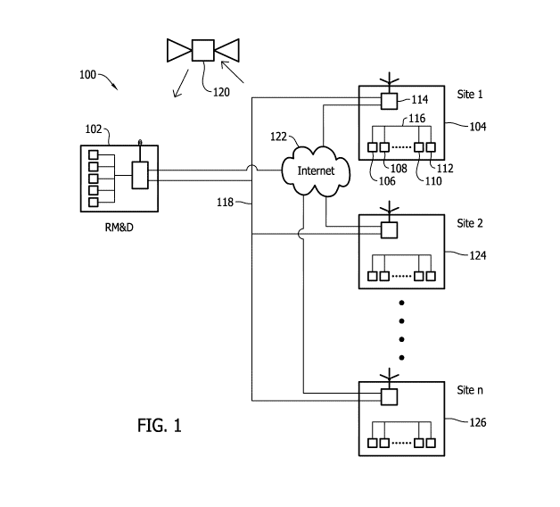
FIG. 1 is a schematic block diagram of a remote monitoring and diagnostic
system in accordance with an exemplary embodiment of the present invention;
FIG. 2 is a block diagram of an exemplary embodiment of a network
architecture of a local industrial plant monitoring and diagnostic system,
such as a
distributed control system (DCS);
CA 02865204 2014-08-21
WO 2013/127996
PCT/EP2013/054158
3
FIG. 3 is a block diagram of an exemplary rule set that may be used with
LMDS shown in FIG. 1;
FIG. 4 is a schematic flow diagram for generating a real-time actual
performance calculation for a centrifugal compressor in accordance with an
exemplary embodiment of the present disclosure.
FIG. 5 is a schematic flow diagram for generating a real-time expected
performance calculation for centrifugal compressor in accordance with an
exemplary
embodiment of the present disclosure.
FIG. 6 is a screen capture of a performance module screen for the compressor
illustrating a visual depiction between actual to expected performance of the
compressor.
FIG. 7 is a flow diagram of a method of the compressor performance
calculation details.
Although specific features of various embodiments may be shown in some
drawings and not in others, this is for convenience only. Any feature of any
drawing
may be referenced and/or claimed in combination with any feature of any other
drawing.
Detailed description of the invention
The following detailed description illustrates embodiments of the invention by
way of example and not by way of limitation. It is contemplated that the
invention
has general application to analytical and methodical embodiments of monitoring
equipment operation in industrial, commercial, and residential applications.
The centrifugal compressor performance rule set described herein permits
operators to know when their machine is not operating as efficiently as
possible or as
efficiently as it once. Knowing the design criteria, as received from the OEM
of the
compressor permits accurate real-time performance display for quick assessment
of
problems and permits detailed assessments of possible sources of the problems.
A
real-time compressor performance advisory for centrifugal compressors
calculates the
'actual' and 'expected' performance of the machine using the OEM design tools
in
place of existing non-physics based methodologies provides higher calculation
accuracies.
CA 02865204 2014-08-21
WO 2013/127996
PCT/EP2013/054158
4
The expected and actual performance calculations are carried out at, for
example, one minute intervals and any anomalous deviation is notified to a
user. The
deviation in threshold along with the time persistence of the deviation
determines the
decision to notify the user.
Based on the severity of the threshold violation, an alarm is generated along
with a performance degradation advisory. The performance degradation advisory
provides the various actions in steps to be performed to identify the possible
sources
of the cause.
The calculation methodology used for 'expected performance' permits each
compressor operator real-time performance envelopes for each snap shot of data
supplied from the monitoring controllers to avoid using only a static
performance
envelope supplied one-time by the OEM during machine commissioning.
Centrifugal compressors are dynamic machines and highly sensitive to the
system resistance and impeller velocities. The system resistance and impeller
velocities are governed by the gas composition and operating conditions.
Performance of these machines can deteriorate due to poor operating condition
or due
to flow passage changes (deposition). Accurate performance estimation, their
interpretation and providing follow-up action (advisory) still remains a
challenging
task mainly due to wide variation in operating conditions within OEM envelope
and
limitation of static baseline or static OEM operating envelope. The methods
described herein dynamically generate the compressor baseline or 'expected
performance' in real-time at predetermined intervals using monitoring system
data.
The dynamic OEM envelope is more realistic to the current operating condition
as
against the static envelope. Also, a methodology is developed to track the
deviation
in actual performance from the dynamic baseline bearing in mind the varying
machine
operating conditions. The OEM design tools are used for the estimation of
actual and
expected performances respectively. The OEM 'As Tested' curves are embedded to
perform the calculations.
As used herein, real-time refers to outcomes occurring at a substantially
short
period after a change in the inputs affecting the outcome, for example,
computational
calculations and/or element linking. The period may be an amount of time
between
iterations of a regularly repeated task. Such repeated tasks are called
periodic tasks.
CA 02865204 2014-08-21
WO 2013/127996
PCT/EP2013/054158
The time period is a design parameter of the real-time system that may be
selected
based on the importance of the outcome and/or the capability of the system
implementing processing of the inputs to generate the outcome. Additionally,
events
occurring in real-time occur without substantial intentional delay. In the
exemplary
embodiment, links are updated and mutations are fired in real-time within
network
and component capabilities.
FIG. 1 is a schematic block diagram of remote monitoring and diagnostic
system 100 in accordance with an exemplary embodiment of the present
invention. In
the exemplary embodiment, system 100 includes a remote monitoring and
diagnostic
center 102. Remote monitoring and diagnostic center 102 is operated by an
entity,
such as, an OEM of a plurality of equipment purchased and operated by a
separate
business entity, such as, an operating entity. In the exemplary embodiment,
the OEM
and operating entity enter into a support arrangement whereby the OEM provides
services related to the purchased equipment to the operating entity. The
operating
entity may own and operate purchased equipment at a single site or multiple
sites.
Moreover, the OEM may enter into support arrangements with a plurality of
operating
entities, each operating their own single site or multiple sites. The multiple
sites each
may contain identical individual equipment or pluralities of identical sets of
equipment, such as trains of equipment. Additionally, at least some of the
equipment
may be unique to a site or unique to all sites.
In the exemplary embodiment, a first site 104 includes one or more process
analyzers 106, equipment monitoring systems 108, equipment local control
centers
110, and/or monitoring and alarm panels 112 each configured to interface with
respective equipment sensors and control equipment to effect control and
operation of
the respective equipment. The one or more process analyzers 106, equipment
monitoring systems 108, equipment local control centers 110, and/or monitoring
and
alarm panels 112 are communicatively coupled to an intelligent monitoring and
diagnostic system 114 through a network 116. Intelligent monitoring and
diagnostic
(IMAD) system 114 is further configured to communicate with other on-site
systems
(not shown in FIG. 1) and offsite systems, such as, but not limited to, remote
monitoring and diagnostic center 102. In various embodiments, IMAD 114 is
CA 02865204 2014-08-21
WO 2013/127996
PCT/EP2013/054158
6
configured to communicate with remote monitoring and diagnostic center 102
using
for example, a dedicated network 118, a wireless link 120, and the Internet
122.
Each of a plurality of other sites, for example, a second site 124 and an nth
site
126 may be substantially similar to first site 104 although may or may not be
exactly
similar to first site 104.
FIG. 2 is a block diagram of an exemplary embodiment of a network
architecture 200 of a local industrial plant monitoring and diagnostic system,
such as a
distributed control system (DCS) 201. The industrial plant may include a
plurality of
plant equipment, such as gas turbines, centrifugal compressors, gearboxes,
generators,
pumps, motors, fans, and process monitoring sensors that are coupled in flow
communication through interconnecting piping, and coupled in signal
communication
with DCS 201 through one or more remote input/output (I/0) modules and
interconnecting cabling and/or wireless communication. In the exemplary
embodiment, the industrial plant includes DCS 201 including a network backbone
203. Network backbone 203 may be a hardwired data communication path
fabricated
from twisted pair cable, shielded coaxial cable or fiber optic cable, for
example, or
may be at least partially wireless. DCS 201 may also include a processor 205
that is
communicatively coupled to the plant equipment, located at the industrial
plant site or
at remote locations, through network backbone 203. It is to be understood that
any
number of machines may be operatively connected to network backbone 203. A
portion of the machines may be hardwired to network backbone 203, and another
portion of the machines may be wirelessly coupled to backbone 203 via a
wireless
base station 207 that is communicatively coupled to DCS 201. Wireless base
station
207 may be used to expand the effective communication range of DCS 201, such
as
with equipment or sensors located remotely from the industrial plant but,
still
interconnected to one or more systems within the industrial plant.
DCS 201 may be configured to receive and display operational parameters
associated with a plurality of equipment, and to generate automatic control
signals
and receive manual control inputs for controlling the operation of the
equipment of
industrial plant. In the exemplary embodiment, DCS 201 may include a software
code segment configured to control processor 205 to analyze data received at
DCS
201 that allows for on-line monitoring and diagnosis of the industrial plant
machines.
CA 02865204 2014-08-21
WO 2013/127996
PCT/EP2013/054158
7
Data may be collected from each machine, including gas turbines, centrifugal
compressors, pumps and motors, associated process sensors, and local
environmental
sensors including, for example, vibration, seismic, temperature, pressure,
current,
voltage, ambient temperature and ambient humidity sensors. The data may be pre-
processed by a local diagnostic module or a remote input/output module, or may
be
transmitted to DCS 201 in raw form.
A local monitoring and diagnostic system (LMDS) 213 may be a separate add-
on hardware device, such as, for example, a personal computer (PC), that
communicates with DCS 201 and other control systems 209 and data sources
through
network backbone 203. LMDS 213 may also be embodied in a software program
segment executing on DCS 201 and/or one or more of the other control systems
209.
Accordingly, LMDS 213 may operate in a distributed manner, such that a portion
of
the software program segment executes on several processors concurrently. As
such,
LMDS 213 may be fully integrated into the operation of DCS 201 and other
control
systems 209. LMDS 213 analyzes data received by DCS 201, data sources, and
other
control systems 209 to determine an operational health of the machines and/or
a
process employing the machines using a global view of the industrial plant.
In the exemplary embodiment, network architecture 100 includes a server
grade computer 202 and one or more client systems 203. Server grade computer
202
further includes a database server 206, an application server 208, a web
server 210, a
fax server 212, a directory server 214, and a mail server 216. Each of servers
206,
208, 210, 212, 214, and 216 may be embodied in software executing on server
grade
computer 202, or any combinations of servers 206, 208, 210, 212, 214, and 216
may
be embodied alone or in combination on separate server grade computers coupled
in a
local area network (LAN) (not shown). A data storage unit 220 is coupled to
server
grade computer 202. In addition, a workstation 222, such as a system
administrator's
workstation, a user workstation, and/or a supervisor's workstation are coupled
to
network backbone 203. Alternatively, workstations 222 are coupled to network
backbone 203 using an Internet link 226 or are connected through a wireless
connection, such as, through wireless base station 207.
Each workstation 222 may be a personal computer having a web browser.
Although the functions performed at the workstations typically are illustrated
as being
CA 02865204 2014-08-21
WO 2013/127996
PCT/EP2013/054158
8
performed at respective workstations 222, such functions can be performed at
one of
many personal computers coupled to network backbone 203. Workstations 222 are
described as being associated with separate exemplary functions only to
facilitate an
understanding of the different types of functions that can be performed by
individuals
having access to network backbone 203.
Server grade computer 202 is configured to be communicatively coupled to
various individuals, including employees 228 and to third parties, e.g.,
service
providers 230. The communication in the exemplary embodiment is illustrated as
being performed using the Internet, however, any other wide area network (WAN)
type communication can be utilized in other embodiments, i.e., the systems and
processes are not limited to being practiced using the Internet.
In the exemplary embodiment, any authorized individual having a workstation
232 can access LMDS 213. At least one of the client systems may include a
manager
workstation 234 located at a remote location. Workstations 222 may be embodied
on
personal computers having a web browser. Also, workstations 222 are configured
to
communicate with server grade computer 202. Furthermore, fax server 212
communicates with remotely located client systems, including a client system
236
using a telephone link (not shown). Fax server 212 is configured to
communicate
with other client systems 228, 230, and 234, as well.
Computerized modeling and analysis tools of LMDS 213, as described below
in more detail, may be stored in server 202 and can be accessed by a requester
at any
one of client systems 204. In one embodiment, client systems 204 are computers
including a web browser, such that server grade computer 202 is accessible to
client
systems 204 using the Internet. Client systems 204 are interconnected to the
Internet
through many interfaces including a network, such as a local area network
(LAN) or a
wide area network (WAN), dial-in-connections, cable modems and special high-
speed
ISDN lines. Client systems 204 could be any device capable of interconnecting
to the
Internet including a web-based phone, personal digital assistant (PDA), or
other web-
based connectable equipment. Database server 206 is connected to a database
240
containing information about industrial plant 10, as described below in
greater detail.
In one embodiment, centralized database 240 is stored on server grade computer
202
and can be accessed by potential users at one of client systems 204 by logging
onto
CA 02865204 2014-08-21
WO 2013/127996
PCT/EP2013/054158
9
server grade computer 202 through one of client systems 204. In an alternative
embodiment, database 240 is stored remotely from server grade computer 202 and
may be non-centralized.
Other industrial plant systems may provide data that is accessible to server
grade computer 202 and/or client systems 204 through independent connections
to
network backbone 204. An interactive electronic tech manual server 242
services
requests for machine data relating to a configuration of each machine. Such
data may
include operational capabilities, such as pump curves, motor horsepower
rating,
insulation class, and frame size, design parameters, such as dimensions,
number of
rotor bars or impeller blades, and machinery maintenance history, such as
field
alterations to the machine, as-found and as-left alignment measurements, and
repairs
implemented on the machine that do not return the machine to its original
design
condition.
A portable vibration monitor 244 may be intermittently coupled to LAN
directly or through a computer input port such as ports included in
workstations 222
or client systems 204. Typically, vibration data is collected in a route,
collecting data
from a predetermined list of machines on a periodic basis, for example,
monthly or
other periodicity. Vibration data may also be collected in conjunction with
troubleshooting, maintenance, and commissioning activities. Further, vibration
data
may be collected continuously in a real-time or near real-time basis. Such
data may
provide a new baseline for algorithms of LMDS 213. Process data may similarly,
be
collected on a route basis or during troubleshooting, maintenance, and
commissioning
activities. Moreover, some process data may be collected continuously in a
real-time
or near real-time basis. Certain process parameters may not be permanently
instrumented and a portable process data collector 245 may be used to collect
process
parameter data that can be downloaded to DCS 201 through workstation 222 so
that it
is accessible to LMDS 213. Other process parameter data, such as process fluid
composition analyzers and pollution emission analyzers may be provided to DCS
201
through a plurality of on-line monitors 246.
Electrical power supplied to various machines or generated by generated by
generators with the industrial plant may be monitored by a motor protection
relay 248
associated with each machine. Typically, such relays 248 are located remotely
from
CA 02865204 2014-08-21
WO 2013/127996
PCT/EP2013/054158
the monitored equipment in a motor control center (MCC) or in switchgear 250
supplying the machine. In addition, to protection relays 248, switchgear 250
may also
include a supervisory control and data acquisition system (SCADA) that
provides
LMDS 213 with power supply or power delivery system (not shown) equipment
located at the industrial plant, for example, in a switchyard, or remote
transmission
line breakers and line parameters.
FIG. 3 is a block diagram of an exemplary rule set 280 that may be used with
LMDS 213 (shown in FIG. 1). Rule set 280 may be a combination of one or more
custom rules, and a series of properties that define the behavior and state of
the
custom rules. The rules and properties may be bundled and stored in a format
of an
XML string, which may be encrypted based on a 25 character alphanumeric key
when
stored to a file. Rule set 280 is a modular knowledge cell that includes one
or more
inputs 282 and one or more outputs 284. Inputs 282 may be software ports that
direct
data from specific locations in LMDS 213 to rule set 280. For example, an
input from
a pump outboard vibration sensor may be transmitted to a hardware input
termination
in DCS 201. DCS 201 may sample the signal at that termination to receive the
signal
thereon. The signal may then be processed and stored at a location in a memory
accessible and/or integral to DCS 201. A first input 286 of rule set 280 may
be
mapped to the location in memory such that the contents of the location in
memory is
available to rule set 280 as an input. Similarly, an output 288 may be mapped
to
another location in the memory accessible to DCS 201 or to another memory such
that
the location in memory contains the output 288 of rule set 280.
In the exemplary embodiment, rule set 280 includes one or more rules relating
to monitoring and diagnosis of specific problems associated with equipment
operating
in an industrial plant, such as, for example, a gas reinjection plant, a
liquid natural gas
(LNG) plant, a power plant, a refinery, and a chemical processing facility.
Although
rule set 280 is described in terms of being used with an industrial plant,
rule set 280
may be appropriately constructed to capture any knowledge and be used for
determining solutions in any field. For example, rule set 280 may contain
knowledge
pertaining to economic behavior, financial activity, weather phenomenon, and
design
processes. Rule set 280 may then be used to determine solutions to problems in
these
fields. Rule set 280 includes knowledge from one or many sources, such that
the
CA 02865204 2014-08-21
WO 2013/127996
PCT/EP2013/054158
11
knowledge is transmitted to any system where rule set 280 is applied.
Knowledge is
captured in the form of rules that relate outputs 284 to inputs 282 such that
a
specification of inputs 282 and outputs 284 allows rule set 280 to be applied
to LMDS
213. Rule set 280 may include only rules specific to a specific plant asset
and may be
directed to only one possible problem associated with that specific plant
asset. For
example, rule set 280 may include only rules that are applicable to a motor or
a motor/
pump combination. Rule set 280 may only include rules that determine a health
of the
motor/pump combination using vibration data. Rule set 280 may also include
rules
that determine the health of the motor/pump combination using a suite of
diagnostic
tools that include, in addition to vibration analysis techniques, but may also
include,
for example, performance calculational tools and/or financial calculational
tools for
the motor/pump combination.
In operation, rule set 280 is created in a software developmental tool that
prompts a user for relationships between inputs 282 and outputs 284. Inputs
282 may
receive data representing, for example digital signals, analog signals,
waveforms,
processed signals, manually entered and/or configuration parameters, and
outputs
from other rule sets. Rules within rule set 280 may include logical rules,
numerical
algorithms, application of waveform and signal processing techniques, expert
system
and artificial intelligence algorithms, statistical tools, and any other
expression that
may relate outputs 284 to inputs 282. Outputs 284 may be mapped to respective
locations in the memory that are reserved and configured to receive each
output 284.
LMDS 213 and DCS 201 may then use the locations in memory to accomplish any
monitoring and/ or control functions LMDS 213 and DCS 201 may be programmed to
perform. The rules of rule set 280 operate independently of LMDS 213 and DCS
201,
although inputs 282 may be supplied to rule set 280 and outputs 284 may be
supplied
to rule set 280, directly or indirectly through intervening devices.
During creation of rule set 280, a human expert in the field divulges
knowledge of the field particular to a specific asset using a development tool
by
programming one or more rules. The rules are created by generating expressions
of
relationship between outputs 284 and inputs 282 such that no coding of the
rules is
needed. Operands may be selected from a library of operands, using graphical
methods, for example, using drag and drop on a graphical user interface built
into the
CA 02865204 2014-08-21
WO 2013/127996
PCT/EP2013/054158
12
development tool. A graphical representation of an operand may be selected
from a
library portion of a screen display (not shown) and dragged and dropped into a
rule
creation portion. Relationships between input 282 and operands are arranged in
a
logical display fashion and the user is prompted for values, such as,
constants, when
appropriate based on specific operands and specific ones of inputs 282 that
are
selected. As many rules that are needed to capture the knowledge of the expert
are
created. Accordingly, rule set 280 may include a robust set of diagnostic
and/or
monitoring rules or a relatively less robust set of diagnostic and/or
monitoring rules
based on a customer's requirements and a state of the art in the particular
field of rule
set 280. The development tool provides resources for testing rule set 280
during the
development to ensure various combinations and values of inputs 282 produce
expected outputs at outputs 284.
FIG. 4 is a schematic flow diagram for generating a real-time actual
performance calculation for a centrifugal compressor 400 in accordance with an
exemplary embodiment of the present disclosure. In the exemplary embodiment,
compressor process parameter values are acquired from for example, a plant
monitoring system that acquires process data from a plurality of components
throughout the plant or a compressor monitoring system (neither shown in FIG.
4)
that acquires data associated with only compressor 400. In various
embodiments, the
compressor process parameter values include compressor suction process
parameter
values and compressor discharge process parameter values. The compressor
suction
process parameter values include, but are not limited to, a suction pressure
[Pin] 402
and a suction temperature [Tin] 404. The compressor discharge process
parameter
values include, but are not limited to, a discharge pressure [130] 406 and a
discharge
temperature [Tout] 408. A mass flow 409 through compressor 400, gas
composition
and gas molecular weight [Mw] and shaft rotating speed [rpm] are also
acquired.
The compressor process parameter values are applied to a polytrophic
thermodynamic algorithm 410 using a more complete set of thermodynamic
transformation and, more important, real gas behavior based on several
equations of
state to determine the actual performance of compressor 400. Moreover,
polytrophic
thermodynamic algorithm 410 and the compressor process parameter values are
used
CA 02865204 2014-08-21
WO 2013/127996
PCT/EP2013/054158
13
to calculate a polytropic efficiency 412, a polytropic head 414, and an
absorbed power
416 for compressor 400.
FIG. 5 is a schematic flow diagram for generating a real-time expected
performance calculation for centrifugal compressor 400 in accordance with an
exemplary embodiment of the present disclosure. In the exemplary embodiment,
compressor process parameter values are acquired from the plant monitoring
system
or the compressor monitoring system (neither shown in FIG. 4). In various
embodiments, the compressor process parameter values include compressor
suction
process parameter values. The compressor suction process parameter values
include,
but are not limited to, a suction pressure [Pin] 402 and a suction temperature
['Lid 404.
The compressor discharge process parameter values are values to be solved for
by a
compressor performance rule set 500. The compressor discharge process
parameter
values to be solved for include, but are not limited to, an expected discharge
pressure
502 and an expected discharge temperature 504.
The compressor process parameter values and as-tested data 508 are applied to
compressor performance rule set 500 to determine the expected performance of
compressor 400. Moreover, compressor performance rule set 500 and the
compressor
process parameter values are used to calculate expected discharge pressure
502,
expected discharge temperature 504, a polytropic efficiency 510, a polytropic
head
512, and an absorbed power 514 for compressor 400.
FIG. 6 is a screen capture of a performance module screen 600 for compressor
400 illustrating a visual depiction between actual to expected performance of
compressor 400. Analysis of compressor 400 performed by compressor performance
rule set 500 is displayed on a plurality of selectable tabs of performance
module
screen 600. For example, a monitoring tab 602, a performance tab 604 (selected
in
FIG. 6), an analysis tab 606, and an information tab 608. Performance module
screen
600 includes a graph area 610 where graphical information is displayed, a
performance parameter value area 612, and an event and alarms area 614 for
displaying information to a user, including a timestamp 616, a source 618, and
a
severity level 620.
FIG. 7 is a flow diagram of a method 700 of compressor performance
calculation details. In the exemplary embodiment, method 700 is a computer-
CA 02865204 2014-08-21
WO 2013/127996
PCT/EP2013/054158
14
implemented method for generating real-time performance advisories for a
centrifugal
compressor of a fleet of centrifugal compressors, method 700 is implemented
using a
computer device coupled to a user interface and a memory device. Method 700
includes receiving 702 compressor process parameter values during operation of
the
compressor. The on-line controller data such as inlet pressure/temperature,
mass
flow, gas composition, exit pressure/temperature and shaft speed is supplied
to
compressor performance rule set 500 at for example, an every minute interval.
Method 700 includes generating 704 a variation notification if suction process
parameter values of the received compressor process parameter values exceed a
predetermined range. If the received compressor process parameter values meet
the
predetermined range, method 700 includes determining 706, in real-time, an
actual
performance of the compressor using a polytrophic thermodynamic algorithm and
the
received inlet pressure/temperature, mass flow, gas composition, exit
pressure/temperature and shaft speed. Method 700 also includes receiving 708
an
actual thermodynamic signature of the compressor, that is unique to the
compressor
from the manufacturer of the compressor and which is a subset of a plurality
of actual
thermodynamic signatures for the fleet of centrifugal compressors, and
determining
710, in real-time, a predicted performance of the compressor using the actual
thermodynamic signature of the compressor and using a more complete set of
thermodynamic transformation and real gas behavior based on several equations
of
state. A performance deviation of the compressor is determined 712 using the
actual
performance and the predicted performance and the performance deviation is
compared to a predetermined threshold range of performance deviation, and a
severity
of the performance deviation is determined 720 based on a degradation of
compressor
performance and a difficulty of mitigating the degradation. A notification to
the user
is generated 722 based on the determined severity. In various embodiments, the
notification includes correlating the performance deviation and the received
compressor process parameter values to generate an advisory guiding the user
with
steps to identify the possible sources of a failure causing the deviation.
Moreover, method 700 also includes determining one or more key
performance indicators (KPI) for the operation of the compressor using the
thermodynamic signature specific to the compressor and comparing the one or
more
CA 02865204 2014-08-21
WO 2013/127996
PCT/EP2013/054158
KPIs to the actual performance to generate one or more KPI performance
deviations
associated with the one or more KPIs. A notification to the user is generated
regarding each KPI performance deviation that exceeds a predetermined KPI
performance deviation threshold range. Further, in various embodiments,
determining
706 the actual performance of the compressor and determining 710 the predicted
performance of the compressor are corrected based on a load on the compressor.
Method 700 also includes determining 714, in real-time, a predicted envelope
of the compressor using the determined actual thermodynamic signature of the
compressor, generating 716 a performance map using the predicted envelope and
the
actual performance, and outputting 718 an advisory message based on the
generated
performance map.
Compressor performance rule set 500 provides high accuracy OEM tools to
calculate the realistic expected performance in real-time, performance
deviation
alarms that considering the wide variation in operational conditions, and
actionable
alarm advisories and performance advisories based on the nature/degree of the
deviation.
The logic flows depicted in the figures do not require the particular order
shown, or sequential order, to achieve desirable results. In addition, other
steps may
be provided, or steps may be eliminated, from the described flows, and other
components may be added to, or removed from, the described systems.
Accordingly,
other embodiments are within the scope of the following claims.
It will be appreciated that the above embodiments that have been described in
particular detail are merely example or possible embodiments, and that there
are many
other combinations, additions, or alternatives that may be included.
Also, the particular naming of the components, capitalization of terms, the
attributes, data structures, or any other programming or structural aspect is
not
mandatory or significant, and the mechanisms that implement the invention or
its
features may have different names, formats, or protocols. Further, the system
may be
implemented via a combination of hardware and software, as described, or
entirely in
hardware elements. Also, the particular division of functionality between the
various
system components described herein is merely one example, and not mandatory;
functions performed by a single system component may instead be performed by
CA 02865204 2014-08-21
WO 2013/127996
PCT/EP2013/054158
16
multiple components, and functions performed by multiple components may
instead
performed by a single component.
Some portions of above description present features in terms of algorithms and
symbolic representations of operations on information. These algorithmic
descriptions
and representations may be used by those skilled in the data processing arts
to most
effectively convey the substance of their work to others skilled in the art.
These
operations, while described functionally or logically, are understood to be
implemented by computer programs. Furthermore, it has also proven convenient
at
times, to refer to these arrangements of operations as modules or by
functional names,
without loss of generality.
Unless specifically stated otherwise as apparent from the above discussion, it
is appreciated that throughout the description, discussions utilizing terms
such as
"processing" or "computing" or "calculating" or "determining" or "displaying"
or
"providing" or the like, refer to the action and processes of a computer
system, or
similar electronic computing device, that manipulates and transforms data
represented
as physical (electronic) quantities within the computer system memories or
registers
or other such information storage, transmission or display devices.
While the disclosure has been described in terms of various specific
embodiments, it will be recognized that the disclosure can be practiced with
modification within the spirit and scope of the claims.
The term processor, as used herein, refers to central processing units,
microprocessors, microcontrollers, reduced instruction set circuits (RISC),
application
specific integrated circuits (ASIC), logic circuits, and any other circuit or
processor
capable of executing the functions described herein.
As used herein, the terms "software" and "firmware" are interchangeable, and
include any computer program stored in memory for execution by processor 205,
including RAM memory, ROM memory, EPROM memory, EEPROM memory, and
non-volatile RAM (NVRAM) memory. The above memory types are exemplary
only, and are thus not limiting as to the types of memory usable for storage
of a
computer program.
As will be appreciated based on the foregoing specification, the above-
described embodiments of the disclosure may be implemented using computer
CA 02865204 2014-08-21
WO 2013/127996
PCT/EP2013/054158
17
programming or engineering techniques including computer software, firmware,
hardware or any combination or subset thereof, wherein the technical effect
includes
(a) receiving an actual thermodynamic signature of the compressor, that is
unique to
the compressor, (b) receiving compressor process parameter values during
operation
of the compressor, (c) determining, in real-time, an actual performance of the
compressor using the compressor process parameter values, (d) determining, in
real-
time, a predicted performance of the compressor using the determined actual
thermodynamic signature of the compressor, (e) determining a performance
deviation
of the compressor using the actual performance and the predicted performance,
(f)
comparing the performance deviation to a predetermined threshold range of
performance deviation (g) generating a notification to a user using the
comparison, (h)
determining one or more key performance indicators (KPI) for the operation of
the
compressor using the thermodynamic signature specific to the compressor, (i)
comparing the one or more KPIs to the actual performance to generate one or
more
KPI performance deviations associated with the one or more KPIs, (j)
generating a
notification to a user regarding each KPI performance deviation that exceeds a
predetermined KPI performance deviation threshold range, (k) determining the
actual
performance and the predicted performance corrected based on a load on the
compressor, (1) receiving the actual thermodynamic signature of the compressor
from
the manufacturer of the compressor, (m) receiving a subset of a plurality of
actual
thermodynamic signatures for the fleet of centrifugal compressors, (n)
receiving
compressor suction process parameter values in real-time during operation of
the
compressor, (o) receiving compressor discharge process parameter values in
real-time
during operation of the compressor, (p) determining, in real-time, a predicted
envelope of the compressor using the determined actual thermodynamic signature
of
the compressor, (q) generating a performance map using the predicted envelope
and
the actual performance, (r) outputting an advisory message based on the
generated
performance map, (s) determining a severity of the performance deviation based
on a
degradation of compressor performance and a difficulty of mitigating the
degradation,
(t) generating a notification to a user based on the determined severity, (u)
correlating
the performance deviation and the received compressor process parameter values
to
generate an advisory guiding the user with steps to identify the possible
sources of a
CA 02865204 2014-08-21
WO 2013/127996
PCT/EP2013/054158
18
failure causing the deviation, (v) generating a variation notification if
suction process
parameter values of the received compressor process parameter values exceed a
predetermined range, (w) determining the actual performance of the compressor
using
a polytrophic thermodynamic algorithm and the compressor process parameter
values.
Any such resulting program, having computer-readable code means, may be
embodied or provided within one or more computer-readable media, thereby
making a
computer program product, i.e., an article of manufacture, according to the
discussed
embodiments of the disclosure. The computer readable media may be, for
example,
but is not limited to, a fixed (hard) drive, diskette, optical disk, magnetic
tape,
semiconductor memory such as read-only memory (ROM), and/or any
transmitting/receiving medium such as the Internet or other communication
network
or link. The article of manufacture containing the computer code may be made
and/or
used by executing the code directly from one medium, by copying the code from
one
medium to another medium, or by transmitting the code over a network.
Many of the functional units described in this specification have been labeled
as modules, in order to more particularly emphasize their implementation
independence. For example, a module may be implemented as a hardware circuit
comprising custom very large scale integration ("VLSI") circuits or gate
arrays, off-
the-shelf semiconductors such as logic chips, transistors, or other discrete
components. A module may also be implemented in programmable hardware devices
such as field programmable gate arrays (FPGAs), programmable array logic,
programmable logic devices (PLDs) or the like.
Modules may also be implemented in software for execution by various types
of processors. An identified module of executable code may, for instance,
comprise
one or more physical or logical blocks of computer instructions, which may,
for
instance, be organized as an object, procedure, or function. Nevertheless, the
executables of an identified module need not be physically located together,
but may
comprise disparate instructions stored in different locations which, when
joined
logically together, comprise the module and achieve the stated purpose for the
module.
A module of executable code may be a single instruction, or many
instructions, and may even be distributed over several different code
segments, among
CA 02865204 2014-08-21
WO 2013/127996
PCT/EP2013/054158
19
different programs, and across several memory devices. Similarly, operational
data
may be identified and illustrated herein within modules, and may be embodied
in any
suitable form and organized within any suitable type of data structure. The
operational
data may be collected as a single data set, or may be distributed over
different
locations including over different storage devices, and may exist, at least
partially,
merely as electronic signals on a system or network.
The above-described embodiments of a method and real-time centrifugal
compressor performance degradation advisory system that includes a rule module
provides a cost-effective and reliable means for providing meaningful
operational
recommendations and troubleshooting actions. Moreover, the system is more
accurate and less prone to false alarms. More specifically, the methods and
systems
described herein can predict component failure at a much earlier stage than
known
systems to facilitate significantly reducing outage time and preventing trips.
In
addition, the above-described methods and systems facilitate predicting
anomalies at
an early stage enabling site personnel to prepare and plan for a shutdown of
the
equipment. As a result, the methods and systems described herein facilitate
operating
gas turbines and other equipment in a cost-effective and reliable manner.
This written description uses examples to disclose the invention, including
the
best mode, and also to enable any person skilled in the art to practice the
invention,
including making and using any devices or systems and performing any
incorporated
methods. The patentable scope of the disclosure is defined by the claims, and
may
include other examples that occur to those skilled in the art. Such other
examples are
intended to be within the scope of the claims if they have structural elements
that do
not differ from the literal language of the claims, or if they include
equivalent
structural elements with insubstantial differences from the literal languages
of the
claims.