Note: Descriptions are shown in the official language in which they were submitted.
8 1 78 1 55 0
A HYDROPHOBIC OR AMPRIPHOBIC ROLL COVER
Related Applications
This application claims the benefit of and priority from U.S. Provisional
Application
Serial Na. 61/621,037, filed on April 6,2012.
Field
The present invention relates generally to industrial rolls, and more
particularly to
covers for industrial rolls.
Background
Cylindrical rolls are utilized itt a -number of industrial applications,
especially those
relating to papermaking. Such rolls are typically employed in demanding
environments in
which they can he exposed to high dynamic loads and temperatures and
aggressive or
corrosive chemical agents. As an example, in a typical paper mill, rolls are
used not only for
transporting a fibrous web sheet between processing stations, but also, in the
case of press
section and calender rolls, for processing the web sheet itself into paper.
Typically rolls used in papermaking are constructed with the location within
the
papermaking machine in mind, as rolls residing in different positions within
the papermaking
machines are required to perform different functions. Because papermaking
rolls can have
many different performance demands, and because replacingin entire metallic
roll can be
quite expensive, many papermaking rolls include a polymeric cover that
surrounds the
circumferential surface of a metallic core. By varying the polymer or
elastomer employed in
the cover, the cover designer can provide the roll with different performance
characteristics
as the papermaking application demands. Also, repair, regrinding or
replacement of a cover
over a metallic roll can be considerably less expensive than the replacement
of an entire
metallic roll.
In many instances, the roll cover will include at least two distinct layers: a
base layer
that overlies the core and provides a bond thereto; and a topstock layer that
overlies and
bonds to the base layer and serves the outer surface of the roll (some rolls
will also include an
interinediate "tie-in" layer sandwiched by the base and top stock layers). The
layers for these
-1-
CA 2865253 2017-10-16
81781550
materials are typically selected to provide the cover with a prescribed set of
physical
properties for operation. These can include the requisite strength, elastic
modulus, and
resistance to elevated temperature, water and harsh chemicals to withstand the
papermaking
environment. In addition, covers are typically designed to have a
predetermined surface
hardness that is appropriate for the process they are to perform, and they
typically require that
the paper sheet "release" from the cover without damage to the paper sheet.
Also, in order to
be economical, the cover should be abrasion- and wear-resistant.
There may be a need for papermaking roll covers that have different balances
of
properties, particularly sheet release and water diffusion.
Summary
As a first aspect, embodiments of the invention are directed to an industrial
roll,
comprising: a substantially cylindrical metallic core; a base layer that is
adhered to and
circumferentially overlies the core; a polymeric topstock layer that
circumferentially overlies
the base layer; and a hydrophobic or amphiphobic coating that
circumferentially overlies the
topstock layer, wherein the polymeric topstock layer comprises polyurethane
and the
hydrophobic or amphiphobic coating comprises a hydrophobic or amphiphobic
compound and
a matrix material comprising polyurethane.
As a second aspect, embodiments of the invention are directed to a method of
constructing an industrial roll having a hydrophobic or amphiphobic coating,
the method
comprising the steps of: providing a substantially cylindrical metallic core;
applying a base
layer that circumferentially overlies the core; and applying a bi-layer over
the base layer, the
bi-layer comprising a topstock layer that circumferentially overlies the base
layer and a
hydrophobic or amphiphobic coating that circumferentially overlies the
topstock layer,
wherein the topstock layer comprises polyurethane and the hydrophobic or
amphiphobic
coating comprises a hydrophobic or amphiphobic compound and a matrix material
comprising polyurethane.
- 2 -
CA 2865253 2017-10-16
CA 02865253 2019-08-21
WO 2013/151743 PCT/US2013/031966
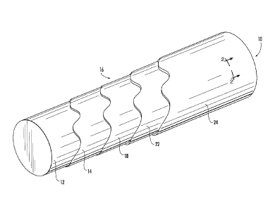
Brief Description of the Figures
Figure 1 is a perspective cutaway view of an industrial roll according to
embodiments
of the present invention.
Figure 2 is a greatly enlarged, partial section view of the roll of Figure 1
taken along
lines 2--2 thereof.
Figure 3 is a greatly enlarged, partial section view of an industrial roll
according to
additional embodiments of the present invention.
Figure 4 is a greatly enlarged, partial section view of an industrial roll
according to
further embodiments of the present invention.
Figure 5 is a greatly enlarged, partial section view of an industrial roll
according to
still further embodiments of the present invention.
Figure 6 is a partial front view of a bi-nozzle system for producing a cover
for an
industrial roll according to embodiments of the present invention.
Figure 7 shows a greatly enlarged, partial section view of a topstock layer
having a
plurality of recesses according to embodiments of the present invention.
Description
The present invention will be described more particularly hereinafter with
reference to
the accompanying drawings. The invention is not intended to be limited to the
illustrated
embodiments; rather, these embodiments are intended to fully and completely
disclose the
invention to those skilled in this art. In the drawings, like numbers refer to
like elements
throughout. Thicknesses and dimensions of some components may be exaggerated
for
clarity. Well-known functions or constructions may not be described in detail
for brevity
and/or clarity.
In addition, spatially relative terms, such as "under", "below", "lower",
"over",
"upper" and the like, may be used herein for ease of description to describe
one element or
feature's relationship to another element(s) or feature(s) as illustrated in
the figures. It will be
understood that the spatially relative terms are intended to encompass
different orientations of
the device in use or operation in addition to the orientation depicted in the
figures. For
example, if the device in the figures is turned over, elements described as
"under" or
"beneath" other elements or features would then be oriented "over" the other
elements or
features. Thus, the exemplary term "under" can encompass both an orientation
of over and
-3-
CA 02865253 2019-08-21
WO 2013/151743 PCT/US2013/031966
under, The device may be otherwise oriented (rotated 90 degrees or at other
orientations) and
the spatially relative descriptors used herein interpreted accordingly.
Unless otherwise defined, all technical and scientific terms used herein have
the same
meaning as commonly understood by one of ordinary skill in the art to which
this invention
belongs. The terminology used in the description of the invention herein is
for the purpose of
describing particular embodiments only and is not intended to be limiting of
the invention.
As used in the description of the invention and the appended claims, the
singular forms "a,"
"an" and "the" are intended to include the plural forms as well, unless the
context clearly
indicates otherwise. As used herein, the term "and/or" includes any and all
combinations of
one or more of the associated listed items. Where used, the terms "attached,"
"connected,"
"interconnected," "contacting," "coupled," "mounted," "overlying" and the like
can mean
either direct or indirect attachment or contact between elements, unless
stated otherwise.
The term "about," as used herein when referring to a measurable value, such as
an
amount or concentration, encompasses variations of the specified measurable
value as well as
the specified value, and may encompass variations of 10%, + 5%, 1%, + 0.5%,
0.1%,
or the like. For example, "about X" where X is the measurable value, is meant
to include X
as well as variations of X that may include 10%, 5%, 1%, 0.5%, 0.1%,
or the like.
A range provided herein for a measureable value may include any other range
and/or
individual value therein.
Referring now to the figures, a roll, designated broadly at 10, is illustrated
in Figures
1 and 2. The roll 10 includes in overlying relationship a core 12 (typically
metallic), an
adhesive layer 14, and a cover 16. Each of these components is discussed in
greater detail
herein below.
The core 12 is a substantially cylindrical, hollow structure typically formed
of steel,
some other metal, or even a composite material. The core 12 is typically
between about 1.5
and 400 inches in length and 1 and 70 inches in diameter, with lengths between
about 100
and 400 inches and diameters of between about 20 and 70 inches being common
for
papermaking purposes. At these more common length and diameter ranges, the
core 12
typically has walls between about 1 and 5 inches in thickness. Components such
as journals
and bearings (not shown) are typically included on the core 12 to facilitate
its mounting and
rotation in a papermaking machine. The surface of the core 12 may be treated
by blasting,
sanding, sandblasting, or the like to prepare the surface for bonding to the
adhesive layer 14.
-4-
CA 02865253 2019-08-21
WO 2013/151743 PCT/US2013/031966
Referring again to Figures 1 and 2, the adhesive layer 14 comprises an
adhesive
(typically an epoxy adhesive) that can attach the core 12 to the cover 16. Of
course, the
adhesive comprising the adhesive layer 14 should be chosen to be compatible
with the
materials of the core 12 and the base layer 18 of the cover 16 (i.e., it
should provide a high-
integrity bond between these structures without unduly harming either
material); preferably,
the bond has a tensile bond strength of between about 1,200 and 5,000 psi. The
adhesive may
have additives, such as curing agents, that facilitate curing and physical
properties.
Exemplary adhesives include Chemlok 220X and Chemlok 205, which are epoxy
adhesives
available from Lord Corporation, Raleigh, North Carolina.
The adhesive layer 14 can be applied to the core 12 in any manner known to be
suitable to those skilled in this art for applying a thin layer of material.
Exemplary application
techniques include spraying, brushing, immersion, scraping, and the like. It
is preferred that,
if a solvent-based adhesive is used, the adhesive layer 14 be applied such
that the solvent can
evaporate prior to the application of the cover 16 in order to reduce the
occurrence of trapped
solvent that can cause "blows" during the curing process. Those skilled in
this art will
appreciate that the adhesive layer 14 may comprise multiple coats of adhesive,
which may
comprise different adhesives; for example, two different epoxy adhesives with
slightly
different properties may be employed. It should also be noted that, in some
embodiments, the
adhesive layer may be omitted entirely, such that the cover 16 is bonded
directly to the core
12.
Still referring to Figures 1 and 2, the cover 16 comprises, in overlying
relationship, a
base layer 18, a topstock layer 22 and a coating 24. In the illustrated
embodiment, the base
layer 18 is adhered to the adhesive layer 14, The base layer 18 comprises a
polymeric
compound that typically includes fillers and other additives. Exemplary
polymeric
compounds include, but are not limited to, polyurethane, natural rubber and
synthetic rubbers
such as nitrile-butadiene rubber (NBR) and hydrogenated nitrile-butadiene
rubber (HNBR),
an ethylene-propylene terpolymer formed of ethylene-propylene diene monomer
(EPDM),
chlorosulfonated polyethylene (CSPE), styrene butadiene (SBR), chloroprene
(CR),
neoprene, isoprene, silicone, fluoroelastomers, thermoset composites, and
blends and co-
polymers thereof, including blends with polyvinylchloride (PVC). In some
embodiments, the
base layer 18 comprises a thermoset based composite. An exemplary polymeric
material that
may be suitable for use in the base layer 18 is epoxy. Additional components,
such as
-5-
CA 02865253 2019-08-21
WO 2013/151743 PCT/US2013/031966
monomers and monomer coagents like trimethyl propane trimethacrylate and 1, 3-
butylene
glycol dimethacrylate, may be added to the base layer 18 to enhance
polymerization.
Fillers are typically added to the base layer 18 to modify the physical
properties of the
compound and/or to reduce its cost. Exemplary filler materials include, but
are not limited to,
inorganic oxides such as aluminum oxide (A1203), silicon dioxide (Si02),
magnesium oxide
(MgO), calcium oxide (CaO), zinc oxide (ZnO) and titanium dioxide (Ti02),
carbon black
(also known as furnace black), silicates such as clays, talc, wollastonite
(CaSiO3), magnesium
silicate (MgSiO3), anhydrous aluminum silicate, and feldspar (KA1Si308),
sulfates such as
barium sulfate and calcium sulfate, metallic powders such as aluminum, iron,
copper,
stainless steel, or nickel, carbonates such as calcium carbonate (CaCo3) and
magnesium
carbonate (MgCo3), mica, silica (natural, fumed, hydrated, anhydrous or
precipitated), and
nitrides and carbides, such as silicon carbide (SiC) and aluminum nitride
(A1N). These fillers
may he present in virtually any form, such as powder, pellet, fiber or sphere.
Also, the base layer 18 may optionally include other additives, such as
polymerization
initiators, activators and accelerators, curing or vulcanizing agents,
plasticizers, heat
stabilizers, antioxidants and antiozonants, coupling agents, pigments, and the
like, that can
facilitate processing and enhance physical properties. These components are
generally
compounded into the polymer prior to the time of application of the base layer
18 to the
adhesive layer 14 or directly to the core 12. Those skilled in this art will
appreciate that the
identity and amounts of these agents and their use in a base layer are
generally known and
need not be described in detail herein.
The base layer 18 can be applied by any manner known to those skilled in this
art to
be suitable for the application of polymers to an underlying surface. In some
embodiments
(particularly those applying a rubber base), the base layer 18 is applied
through an extrusion
process in which strips of the base layer 18 are extruded through an extrusion
die, then, while
still warm, are overlaid over the adhesive layer 14 as it is still somewhat
tacky. The base
layer strips are preferably between about 0.030 and about 0.125 inches in
thickness and are
applied in an overlapping manner, with the result that total thickness of the
base layer 18 is
typically between about 0.0625 inches and about 1 inch, in some embodiments
between about
0.1 inches and about 0.5 inches, and in further embodiments between about 0.1
inches and
about 0.25 inches. Those skilled in this art will appreciate that, in some
embodiments, the
-6-
CA 02865253 2019-08-21
WO 2013/151743 PCT/US2013/031966
base layer 18 may be omitted such that the topstock layer 22 is adhered
directly to the
adhesive layer 14 or, in the absence of an adhesive layer, to the core 12.
Referring again to Figures 1 and 2, in the illustrated embodiment, the
topstock layer
22 circumferentially overlies and, unless one or more tie-in layers are
included as described
below, is adhered to the base layer 18. The topstock layer 22 comprises a
rubber compound,
such as NBR, HNBR, EPDM, CSM, or natural rubber, or a polyurethane compound
known to
those skilled in this art to be suitable for use in papermaking machine rolls,
Typically the
topstock layer 22 includes fillers and other additives, and may include one or
more recesses,
such as grooves, through holes and/or blind drilled holes, if desired.
Conventionally, a rubber
topstock layer 22 will overlie a rubber base layer 18, whereas a polyurethane
topstock layer
22 will overlie an epoxy base layer 18 via casting the polyurethane layer.
Exemplary fillers include, but are not limited to, silicone dioxide, carbon
black, clay,
and titanium dioxide (Ti02) as well as others set forth hereinabove in
connection with the
base layer 18. Typically, fillers are included in an amount of between about 3
and 70 percent
by weight of the topstock layer 22. The fillers can take virtually any form,
including powder,
pellet, bead, fiber, sphere, or the like.
Exemplary additives include, but are not limited to, polymerization
initiators,
activators and accelerators, curing or vulcanizing agents, plasticizers, heat
stabilizers,
antioxidants, coupling agents, pigments, and the like, that can facilitate
processing and
enhance physical properties. Those skilled in this art will understand the
types and
concentrations of additives that are appropriate for inclusion in the topstock
layer 22, so these
need not be discussed in detail herein.
The topstock layer 22 can be applied over the base layer 18 by any technique
known
to those skilled in this art to be suitable for the application of elastomeric
materials over a
cylindrical surface. Preferably, the components of the topstock layer 22 are
mixed separately,
then blended in a mill. The blended material is transferred from the mill to
an extruder,
which extrudes feed strips of top stock material onto the base layer 18.
Alternatively, either
or both of the base and top stock layers 18, 22 can be applied through the
overlaying of
calendered sheets of material.
In some embodiments, the topstock layer 22 is applied such that it is between
about
0.25 inches and about 2.5 inches in thickness (at higher thickness, multiple
passes of material
may be required), In some embodiments, the topstock layer 22 has a thickness
between about
-7-
CA 02865253 2019-08-21
WO 2013/151743 PCT/US2013/031966
0.5 inches and about 1.5 inches and in some embodiments between about 1 inch
and about
1.5 inches. It is also suitable for the thickness of the top stock layer 22 be
between about 50
and 90 percent of the total cover thickness (i.e., the total thickness of the
combined base and
topstock layers 18, 22 and coating 24). The rubber compounds of the base layer
18 and the
topstock 22 may be selected such that the base layer 18 has a higher hardness
value than the
topstock layer 22. As an example, the base layer 18 may have a hardness of
between about 1
and 100 P&J (in some embodiments, between 3 and 100 P&J, and in other
embodiments,
between 3 and 20 P&J), and the top stock layer 22 may have a hardness of
between about 30
and 300 P&J (in some embodiments between 30 and 250 P&J). The graduated
hardness
concept can reduce the bond line shear stresses that can occur due to
mismatches of the
elastic properties (such as elastic modulus and Poisson's ratio) of the
various layers in the
cover constructions. This reduction in interface shear stress can be important
in maintaining
cover integrity.
Those skilled in this art will also appreciate that the roll 10 may be
constructed with a
tie-in layer sandwiched between the base layer 18 and the topstock layer 22,
such that the tie-
in layer would directly underlie the top stock layer 22. The typical
properties of a tie-in
layer are well-known to those skilled in this art and need not be described in
detail herein.
After the topstock 22 has been applied, these layers of the cover 16 arc then
cured,
typically in an autoclave, for a suitable curing period (generally between
about 16 and 30
hours). After curing, it is preferred that any crust that has developed is
skimmed from the
surface of the top stock layer 22, and that the top stock layer 22 is ground
for dimensional
correctness.
Referring once again to Figures 1 and 2, the coating 24 is then applied over
the
topstock 22. The coating 24 comprises a hydrophobic compound and/or an
amphiphobic
compound and optionally a matrix material. "Hydrophobic," as used herein in
reference to a
surface, coating, and the like, refers to a surface that has a contact angle
greater than 90 for
water, and in some embodiments, a contact angle greater than 120 , 130 , or
even 140 for
water, "Amphiphobic," as used herein in reference to a surface, coating, and
the like, refers
to a surface that has a contact angle greater than 90 for water and an
organic liquid, and in
some embodiments, a contact angle greater than 120 , 130 , or even 140 for
water and an
organic liquid. "Organic liquid," as used herein, refers to a hydrophobic
compound
comprising carbon and hydrogen. Exemplary organic liquids include, but are not
limited to,
-8-
CA 02865253 2019-08-21
WO 2013/151743 PCT/US2013/031966
an oil, a fat, an alkane, an alkylene, an alkync, an arenc, and any
combination thereof. The
coating 24 comprises a sufficient amount of a hydrophobic and/or amphiphobic
compound to
render the outer surface of roll cover 16 hydrophobic and/or amphiphobic. A
hydrophobic
roll cover 16 can repel water and an amphiphobic roll cover 16 can repel water
and an
organic liquid.
According to some embodiments, the coating 24 comprises a superhydrophobic
compound and/or a superamphiphobic compound and optionally a matrix material.
"Superhydrophobic," as used herein, refers to a surface that has a contact
angle greater than
1500 for water. "Superamphiphobic," as used herein, refers to a surface that
has a contact
angle greater than 1500 for water and an organic liquid.
Any method known to those of skill in the art can be used to measure the
contact
angle of water or an organic liquid, such as, but not limited to the static
sessile drop method,
the dynamic sessile drop method, optical tensiometry, force tensiometry, and
any
combination thereof. The contact angle of a drop of water or an organic liquid
on a surface
of a substrate (e.g., the surface of the coating 24) can be measured. The drop
can be about 1
1_, to about 1 mL, or any range therein, such as, but not limited to, about 1
[AL to about 500
p,L, about 1 uL to about 30 pl, about 25 [AL to about 100 uL, or about 3 pi to
about 10 pI.
Exemplary hydrophobic and/or amphiphobic compounds include, but are not
limited
to, polytetrafluoroethylene (PTFE); polyethylene; hydrophobic and/or
amphiphobic
diatomaceous earth; a hydrophobic and/or amphiphobic nanomaterial such as, but
not limited
to, carbon, silica, and/or a metal oxide (e.g., boron oxide, titanium dioxide,
vanadium
pentaoxide, etc.) nanoparticle, nanorod, nanotube, nanofiber, nanopin, and/or
the like; and
any combination thereof. A hydrophobic and/or amphiphobic compound can have a
size in a
range of about 10 nm to about 500 um or any range and/or individual value
therein, such as
about 10 nm to about 10 [AM or about 10 nm to about lum.
A surface of a hydrophobic and/or amphiphobic compound, such as, but not
limited to
a nanomaterial, may be modified with a chemical moiety. Modifying a surface of
a
hydrophobic and/or amphiphobic compound may increase and/or provide the
desired
hydrophobic and/or amphiphobic property and may be accomplished by chemically
and/or
physically bonding the moiety to a surface of the hydrophobic and/or
amphiphobic
compound. Exemplary chemical moieties that may be used to modify a surface of
a
hydrophobic and/or amphiphobic compound include, but are not limited to, a
hydrocarbon, a
-9-
CA 02865253 2016-02-29
= 77203-276
fluorocarbon, a silicon containing compound such as a silane, an organic
amine, stearic acid,
t-butyltrichlorosilane, (3-acryloxypropyl)trimethoxy silane,
methacryloxymethyltriethoxy
silane, cyclopentyltrimethoxysilane,
cyclohexyltrimethoxysilane,
adamantylethyltrichlorosilane, 4-phenylbutyltrichlorosilane, 1-
napthyltrimethoxysilane,
(3,3,3-trifluoropropyl)trimethoxysilane, (tridecafluoro-1,1,2,2-
tetrahydrooctyl)trichlorosilane,
tridecafluoro-2-(tridecafluorohexyl) decyltrichlorosilane,
(heptadecafluoro-1,1,2,2-
tetrahydrodecyl)dimethylchlorosilane, dimethyldimethoxy silane, dodecylamine,
octylamine,
and any combination thereof.
Exemplary matrix materials include, but are not limited to, a polymeric
compound,
such as a rubber compound, an acrylic polymer, a polyurethane, an epoxy, a
latex, etc.
Exemplary rubber compounds include, but are not limited to, NBR, HNBR, EPDM,
CSM,
and/or a natural rubber. Exemplary polyurethane compounds include, but are not
limited to,
those formed from cast and ribbon flow processes and those described in U.S.
Patent No.
6,328,681.
A hydrophobic and/or amphiphobic coating 24 can comprise a mixture of
hydrophobic and/or amphiphobic compounds having different sizes and/or
different
morphologies. In certain embodiments, a hydrophobic and/or amphiphobic coating
24 can
comprise a hydrophobic and/or amphiphobic compound that is uniform in size. In
some
embodiments, a hydrophobic and/or amphiphobic compound is mixed with a solvent
(e.g.,
water and/or an organic liquid) and applied to a roll 10. In certain
embodiments, a
hydrophobic and/or amphiphobic compound is mixed with a matrix material and
applied to a
roll 10.
A hydrophobic and/or amphiphobic coating 24 can comprise about 1 part to about
100
parts of a hydrophobic and/or amphiphobic compound against 100 parts of a
matrix, material
(e.g., a rubber and/or a polyurethane), or any range and/or individual value
therein, such as,
but not limited to, about 1 part to about 25 parts, about 5 parts to about 30
parts, about 10
parts to about 40 parts, about 15 part to about 45 parts, about 20 parts to
about 80 parts, or
about 50 parts to about 100 parts against a matrix material. In some
embodiments, a
hydrophobic and/or amphiphobic coating 24 comprises a mixture of PTFE powder
and
hydrophobic diatomaceous earth. A coating mixture can comprise about 1 part to
about 50
parts of PTFE powder against a matrix material and about 1 part to about 50
parts of
hydrophobic diatomaceous earth against a matrix material. In certain
embodiments, a
-10-
CA 02865253 2019-08-21
WO 2013/151743 PCT/US2013/031966
hydrophobic and/or amphiphobic coating 24 comprises a mixture comprising about
1 part to
about 50 parts of PTFE powder against a matrix material, about 1 part to about
50 parts of
hydrophobic diatomaceous earth against a matrix material, and about 1 part to
about 50 parts
of a hydrophobic nanomaterial, such as, but not limited to, nano-silica (e.g.,
a silica
nanoparticle, nanorod, nanotube, nanofiber, nanopin, and/or the like), against
a matrix
material. In some embodiments, the hydrophobic nanomaterials comprise a
surface coating
comprising hydrocarbon and/or fluorocarbon compounds.
In some embodiments, the coating 24 comprises a mixture comprising about 30
parts
or less of PTFE powder, about 10 parts of less of hydrophobic diatomaceous
earth, and about
parts or less of a nanomaterial. =Those skilled in this art will appreciate
that a hydrophobic
and/or amphiphobic compound can be present in substantially the same
concentration
throughout the coating 24 or the concentration of a hydrophobic and/or
amphiphobic
compound can vary throughout the coating 24. In some embodiments, the ratio of
a
hydrophobic and/or amphiphobic compound to a matrix material varies throughout
the
coating 24.
In certain embodiments, a hydrophobic and/or amphiphobic coating 24 is bionic.
"Bionic," as used herein, refers to the structural similarity of the coating
24 to a hydrophobic
and/or amphiphobic surface found in nature, such as, but not limited to, a
surface of a lotus
leaf. The coating 24 can resemble a natural hydrophobic and/or amphiphobic
surface on the
micro- and/or nano-scale. For example, bionic can refer to how a hydrophobic
compound is
organized to form the coating 24, the surface-energy of the coating 24, and/or
a hierarchical
micro- and/or nano-structure of the coating 24 compared to a natural
hydrophobic and/or
amphiphobic surface. In particular embodiments, the coating 24 is bionic in
that it resembles
a micro- and/or nano-scale structure of a surface of a lotus leaf. The coating
24 can self-
assemble. "Self-assemble," as used herein, refers to the components of a
hydrophobic and/or
amphiphobic coating (e.g., a hydrophobic and/or amphiphobic compound, matrix,
etc.)
assembling into the hydrophobic and/or amphiphobic coating through their own
interactions
and without external guidance and/or means, such as, e.g., adding a catalyst,
heat, light, pH,
etc. (i.e., the coating 24 builds itself). In some embodiments, the coating 24
can self-
assemble, but external means can influence a property of the coating 24, such
as, but not
limited to, the rate of assembly and/or hardness of the coating. In certain
embodiments, the
coating 24 is a self-assembled bionic micro- and/or nano-structure.
-11-
CA 02865253 2016-02-29
= 77203-276
In some embodiments, a hydrophobic and/or amphiphobie coating 24 is between
about 0.005 and 0.200 inches in thickness. In certain embodiments, a
hydrophobic and/or
amphiphobic coating has a hardness of between about 3 and 70 P&J, between
about 3 and 30
P&J, or may even have a hardness of about 100 Shore D.
A hydrophobic and/or amphiphobic coating 24 may have other fillers and
additives of
the type described above in connection with the rubber compounds of the base
and top stock
layers 18, 22 that can modify or enhance its physical properties and
manufacturing
characteristics. Exemplary materials, additives and fillers are set forth in
U.S. Patent Nos.
4,224,372 to Romansld, 4,859,396 to Krenkel et al. and 4,978,428 to Cronin et
al..
A hydrophobic and/or amphiphobic coating 24 can be applied over the top stock
22 in
any manner known to those skilled in this art, including extrusion, casting,
spraying, roller
coating, and the like. In certain embodiments, a hydrophobic and/or
amphiphobic coating 24
may be applied to the topstock 22 by thermal spraying and/or solvent spraying.
Referring again to Figures 1 and 2, after application of the coating 24, the
roll 10 may
optionally be cured (typically via the application of heat), and may be ground
and/or
otherwise finished in a manner known to those skilled in this art.
Another embodiment of a roll cover, designated at 110, is illustrated in
Figure 3. The
roll 110 comprises, in overlying relationship, a core 112, an adhesive layer
114, a base layer
118, a topstock layer 122, and a coating 124 comprising a concentration
gradient of a
hydrophobic and/or amphiphobic compound that increases in concentration as the
coating
124 extends distally from the core 112. The coating 124 can comprise a single
layer or two
or more layers.
Referring to Figures 1-3, to address a potential issue of poor bonding between
a
hydrophobic and/or amphiphobic coating 24, 124 and the topstock 22, 122, it
may be
desirable to apply multiple layers of coating 24, 124 where the bottom layers
of the coating
contain minimum or no amounts of a hydrophobic and/or amphiphobic compound and
increasing amounts of a hydrophobic and/or amphiphobic compound are provided
in one or
more top layers of the coating. Those skilled in the art will appreciate that
when a coating
comprises multiple layers, the concentration of a hydrophobic and/or
amphiphobic compound
can be selected to vary in any manner in the coating layers.
-12-
CA 02865253 2019-08-21
WO 2013/151743 PCT/US2013/031966
Referring now to Figure 4, a roll 210 comprising, in overlying relationship, a
base
layer 218, a topstock layer 222, a transition layer 223, and a hydrophobic
and/or amphiphobic
coating 224 can be formed using a hi-layer coating mechanism comprising a bi-
nozzle system
600 for a ribbon casing machine, such as a ribbon casting polyurethane
machine. A bi-layer
coating mechanism may be used to address a potential issue of poor bonding
between a
hydrophobic and/or amphiphobic coating 224 and topstock 222. The bi-nozzle
system 600
can apply a hi-layer comprising a hydrophobic and/or amphiphobic coating 224
and topstock
222. The hi-nozzle system 600 can comprise a first nozzle 624 that casts a top
ribbon
comprising a hydrophobic and/or amphiphobic compound to form the coating 224
and that is
placed directly above a second nozzle 622 that casts a bottom ribbon
comprising a topstock
material (e.g., a polyurethane or a rubber) without a hydrophobic and/or
amphiphobic
compound to form the topstock 222. The coating 224 can have a thickness
between about
0.0625 inches and about 1.5 inches and in some embodiments between about 0.050
inches
and about 0.250 inches. The topstock 222 can have a thickness between about
0.0625 inches
and about 1.5 inches and in some embodiments between about 0.5 inches and
about 1.5
inches. The two ribbons can be cast simultaneously and can provide interphase
mixing
between the two ribbons to form a transition layer 223. The transition layer
223 can
comprise a concentration gradient of a hydrophobic and/or amphiphobic compound
that
decreases in concentration from the top ribbon to the bottom ribbon in the
bilayer. The hi-
layer coating mechanism can eliminate the distinct interphase that can be
present between a
hydrophobic and/or amphiphobic coating and a topstock containing no
hydrophobic and/or
amphiphobic compounds and can maximize the bonding strength between the
coating and
topstock. As described above, after application of the coating 224, the roll
210 can undergo
further processing/finishing steps known to those skilled in this art.
An industrial roll comprising a hydrophobic and/or a amphiphobic roll cover
can
provide better release properties to the roll cover and can provide protection
against water
swelling and solvent attack. An industrial roll comprising a hydrophobic
and/or a
amphiphobic roll cover can prevent the buildup of papermaking materials on the
roll cover
during operation. Materials such as cellulose, paper fillers, deposits from
recycled paper such
as latexes, and deposits known as "stickies" can cause runnability issues with
roll covers
because they buildup on the surface of the covers. Thus, the industrial rolls
of the present
invention can reduce runnability issues caused by the buildup of papermaking
materials on
-13-
CA 02865253 2019-08-21
WO 2013/151743 PCT/US2013/031966
the roll cover during operation. In certain embodiments, a hydrophobic and/or
amphiphobic
roll cover can provide better sheet release, provide protection against water
diffusion, and
protect against solvent attack, especially for the case of amphiphobic roll
cover.
Referring now to Figure 5, in further embodiments the roll 310 comprises, in
overlying relationship, a core 312, an adhesive layer 314, a base layer 318,
and a topstock
layer 322 comprising a hydrophobic and/or amphiphobic compound. The
hydrophobic
and/or amphiphobic layer 322 includes a hydrophobic and/or amphiphobic
compound, such
as PTFE and/or nano-silica, in an amount sufficient to provide the topstock
layer 322 with
hydrophobic and/or amphiphobic properties. A hydrophobic and/or amphiphobic
topstock
layer 322 can be applied to a roll 310 as described above. A hydrophobic
and/or
amphiphobic compound can be present in substantially the same concentration
throughout the
topstock 322 or the concentration of a hydrophobic and/or amphiphobic compound
can vary
throughout the topstock 322. As an example, the roll 410 of Figure 6
comprises, in
overlying relationship, a core 412, an adhesive layer 414, a base layer 418,
and a topstock
layer 422 comprising a concentration gradient of a hydrophobic and/or
amphiphobic
compound, wherein the concentration of the hydrophobic and/or amphiphobic
compound
increases in topstock 422 as the topstock 422 extends distally from the core
412. Referring to
Figures 5 and 6, in certain embodiments, a topstock 322 or 422 can comprise
two or more
layers and each layer can comprise the same and/or a different concentration
of a
hydrophobic and/or amphiphobic compound as another layer.
According to some embodiments, a hydrophobic and/or amphiphobic coating can
protect all or part of the inside of a recess, such as a groove, a through
hole, and/or a blind
drilled hole, on a roll cover. As illustrated in Figure 7, a hydrophobic
and/or amphiphobic
coating 24' can coat some or all of an interior surface of a recess 34 in a
topstock layer 22'.
Coating an interior surface of a recess 34 with a hydrophobic and/or
amphiphobic coating 24'
can greatly improve water removal from a recess after exiting the nip in a
paper machine.
Also, coating an interior surface of a recess 34 with a hydrophobic and/or
amphiphobic
coating 24' can minimize the amount of surface exposed to water and/or solvent
penetration
and can limit water diffusion to one direction vertical to the working surface
(L e., from the
surface toward the core). Further, coating an interior surface of a recess 34
with a
hydrophobic and/or amphiphobic coating 24' can help to improve the long term
compression
performance of a roll cover under constant water and/or solvent attack. A
hydrophobic
-14-
CA 02865253 2019-08-21
WO 2013/151743 PCT/US2013/031966
and/or amphiphobic coating 24' on an inside surface of a recess 34 can
increase the lifetime
of a roll cover.
As those skilled in the art will appreciate, a hydrophobic and/or amphiphobic
coating
24' on an interior surface of a recess 34 can comprise a hydrophobic and/or
amphiphobic
compound and optionally any suitable matrix material. The same or different
matrix
materials may be used in a hydrophobic and/or amphiphobic coating 24' on an
interior
surface of a recess 34 compared to the matrix materials used in a hydrophobic
and/or
amphiphobic coating on a surface of a roll. A coating 24' on an interior
surface of a recess 34
can be carried out by any known mechanism. In certain embodiments, coating an
interior
surface is a recess 34 is carried out so that there is no excess force applied
onto the interface
and there is no abrasive nature at those surfaces. In some embodiments, a
hydrophobic
and/or amphiphobic coating 24' forms a self-assembled bionic micro- and/or
nano-structure
that repels water and/or an organic liquid.
The following examples are included to demonstrate embodiments of the present
invention and arc not intended to be a detailed catalog of all the different
ways in which the
present invention may be implemented or of all the features that may be added
to the present
invention. Persons skilled in the art will appreciate that numerous variations
and additions to
the various embodiments may be made without departing from the present
invention. Hence,
the following descriptions are intended to illustrate some particular
embodiments of the
invention, and not to exhaustively specify all permutations, combinations and
variations
thereof.
Examples
Example 1
Hydrophobic powder was incorporated into a solvent for a coating application.
This
mixture was then applied to the top layer of a polyurethane roll cover which
created a
hydrophobic surface. This mixture of solvent and hydrophobic powder was also
applied
between layers of polyurethane. This application was to simulate the addition
of the
hydrophobic powder into the ribbon of polyurethane during the casting process
of roll covers.
The incorporation of the hydrophobic powder into prepolymer as a filler was
also achieved.
Using a standard polyurethane formula, the hydrophobic filler was added at
various loadings,
-15-
CA 02865253 2019-08-21
WO 2013/151743 PCT/US2013/031966
blended, then cured to create a polyurethane cover that had hydrophobic
characteristics not
only on the surface of the polyurethane but throughout the entire cover.
Regarding hydrophobic roll covers, it was determined that the incorporation of
functional hydrophobic filler may be a particularly feasible approach, as
other currently
available approaches which induce desirable surface patterns may not be able
to withstand
the abrasive operating conditions between the working roll covers surface and
the passing
sheets. It was suggested that the application of a hydrophobic surface,
perhaps in the form of
amphiphobic coating at the inside of a groove and a drill hole on the roll
cover, may be
desirable, considering it is not a working surface and the coating will only
need to adhere
well to the roll with much less stress imposed onto the interface.
Additionally, this coating
can protect the inside of grooves and drill holes, which can greatly improve
the water
removal exiting the nip. Another advantage of having this hydrophobic or
amphiphobic
surface at the inside of a groove and a drill hole is that it can minimize the
amount of surface
being exposed to water and solvent penetration and limit the water diffusion
to one direction
(from surface toward the core), thereby helping to improve the long term
compression
performance of the grooved and drilled roll cover under constant water and
solvent attack. To
realize a hydrophobic roll cover or a amphiphobic roll cover with a
hydrophobic or
amphiphobic working surface, it was suggested that the application method of
thermal spray
is a desirable option, in which case binding matrix mixed with functional
filler may be either
premixed or even precompounded as a solid feed. Multiple coating layers can be
used to
build up the final coating and the mixing ratio of each layer can be changed
to maximize the
adhesion of the coating to the surface while maximizing the functional filler
loading on the
surface layer without jeopardizing the adhesion strength at the interface.
Also proposed was a
bi-layer coating mechanism for a ribbon casting PU machine, in which a nozzle
casting the
top ribbon containing the functional filler is placed right on top of another
nozzle containing
the bottom ribbon without filler incorporation. The two ribbons are cast
simultaneously and
can provide interphase mixing between the two ribbons and form a gradient
filler
concentration from the top ribbon to the bottom ribbon, which can eliminate
the distinct
interphase and maximize the bonding strength.
-16-
CA 02865253 2019-08-21
WO 2013/151743 PCT/US2013/031966
Example 2
Isocyanate prepolymer resin 20g
Teflon powder 6g
High density polyethylene powder 7g
Clay 2g
Ethaeure 300 Curative 2.8g
The mixture described above was diluted with 60 grams of solvent (5:1 mixture
of
methyl ethyl ketone and toluene) and was sprayed onto the surface of a roll.
After being
cured at elevated temperature, the coating was ground with 180 grit sandpaper.
The contact
angle of finished surface was measured to be 123 . Ethacure0 300 curative is a
liquid
urethane curative available from Albemarle Corporation of Baton Rouge, LA.
Example 3
Isocyanate prepolymer resin 20g
Teflon powder 15g
Ethaeure0 300 Curative 2.8g
The mixture described above was diluted with 60 grams of solvent (5:1 mixture
of
methyl ethyl ketone and toluene) and was sprayed onto the surface of a roll.
After being
cured at elevated temperature, the coating was ground with 180 grit sandpaper.
The contact
angle of finished surface was measured to be 140 .
Example 4
Isocyanate prepolymer resin 30g
Teflon powder 9g
Hydrophobic diatomaceous earth 1.5g
Ethaeuret 300 Curative 4.4g
The mixture described above was diluted with 60 grains of solvent (5:1 mixture
of
methyl ethyl ketone and toluene) and was sprayed onto the surface of a roll.
After being
cured at elevated temperature, the coating was ground with 180 grit sandpaper.
The contact
angle of finished surface was measured to be 145 ,
-17-
CA 02865253 2016-02-29
= 77203-276
Example 5
Isoeyanate prepolymer resin 20g
Teflon powder lOg .
High density polyethylene powder 5g
Ethacure 300 Curative 2.8g
The mixture described above was diluted with 60 grams of solvent (5:1 mixture
of
methyl ethyl ketone and toluene) and was sprayed onto the surface of a roll.
After being
cured at elevated temperature, the coating was ground with 180 grit sandpaper.
The contact
angle of finished surface was measured to be 132 .
The foregoing is illustrative of the present invention and is not to be
construed as
limiting thereof. Although exemplary embodiments of this invention have been
described,
those skilled in the art will readily appreciate that many modifications are
possible in the
exemplary embodiments without materially departing from the novel teachings
and
advantages of this invention. Accordingly, all such modifications are intended
to be included
within the scope of this invention as defined in the claims. The invention is
defined by the
following claims.
-18-