Note: Descriptions are shown in the official language in which they were submitted.
81781664(86216-7)
POWER TRANSMISSION SWITCHING
BACKGROUND
[0001] Typically, power generation plants provide electricity to end-users
via an
electrical distribution network. Power generated by a power plant is provided
to a transmission
network, which provides electricity to a distribution network, which provides
electricity to end-
users. Different companies may own different parts of an electrical
distribution network, and
different portions of electrical network may have different costs associated
it. For example, the
cost to generate electricity at one power generation plant can vary when
compared with the next.
Also, the cost to transmit a given amount of electricity over one portion of
the transmission
network can differ from the cost to transmit the same amount of electricity
over a different
portion of the transmission network.
[0002] One method to control the generation and distribution of electricity
is called
economic dispatch. Economic dispatch typically involves the short-term
determination of the
optimal output of a number of electricity generation facilities, to meet the
system load, at the
lowest possible cost, while providing power in a robust and reliable manner.
Economic dispatch
systems typically use specialized computer software that is configured to
honor operational and
system constraints of the available resources and corresponding transmission
capabilities.
SUMMARY
[0003] In general, in an aspect, embodiments of the invention may provide a
computerized
method implemented on one or more processors for transmission network control,
the
transmission network including transmission lines and corresponding switches,
the transmission
network being configured for use in providing electricity from a generator to
an end user, the
method including receiving and storing at the one or more processors a
sensitivity parameter,
identifying, using the one or more processors, a switchable set of switches
within the
transmission network using the sensitivity parameter, determining, using the
one or more
processors, a candidate switch from the switchable set to change a
corresponding state, wherein
the state can be changed from open to closed and closed to open, determining,
using the one or
more processors, a proposed change of state of the candidate switch, updating,
using the one or
- 1 -
CA 2865286 2019-06-06
81781664(86216-7)
more processors, an optimal power flow (Off) problem stored in a memory as a
function of the
candidate switch and the proposed change of state, deteiiiiining, using the
one or more
processors, and storing in a memory a solution to the updated OPF problem,
generating, using
the one or more processors, an updated sensitivity parameter based on the
stored solution to the
updated OPF problem, and determining, using the updated sensitivity parameter,
if the stored
solution to the updated OPF problem meets a predetermined criterion.
[0004] Implementations of the invention may include one or more of the
following
features. The method includes determining if the solution to the updated OPF
problem is
feasible. The method further includes reverting to a prior OPF solution if the
solution to the
updated OPF problem is not feasible. The method includes determining if the
solution to the
updated OPF problem results in a performance improvement of the transmission
network from a
prior OPF solution. The method includes determining if an operating cost of
the transmission
network changes. The method further includes iteratively performing each of
the steps until a
stopping criterion is satisfied. The sensitivity parameter includes one of a
physical sensitivity
parameter, economic sensitivity parameter, and an environmental sensitivity
parameter. The
method includes generating the updated sensitivity parameter based on at least
one of a
locational price and a shadow price of a transmission constraint. The
predetermined criterion is
a function of whether the solution to the updated OPF problem i) is feasible,
and ii) will result in
a performance improvement of the transmission network, and the method further
comprises
implementing the solution to the updated OPF problem if the predetermined
criterion is satisfied.
[0005] Implementations of the invention may also provide one or more of the
following
features. The method includes identifying which transmission line within the
transmission
network is the least profitable. The method includes determining price
differences between end
nodes of a plurality of transmission lines in the transmission network, and
identifying which of
the price differences is largest. The method includes, determining absolute
values of price
differences between end nodes of a plurality of transmission lines in the
transmission network,
and identifying which of the absolute values is largest. The method includes
determining cost
derivatives associated with a plurality of transmission lines in the
transmission network, and
identifying the cost derivative having the most negative cost impact. The
method includes
determining power transfer distribution factors associated with a plurality of
transmission lines
in the transmission network, and identifying the power transfer distribution
factor having the
most negative value.
- 2 -
CA 2865286 2019-06-06
81781664(86216-7)
[0006] In general, in another aspect, embodiments of the invention may
provide a
tangible computer readable medium including instructions that, when executed
by a computer,
cause the computer to receive a sensitivity parameter, identify a switchable
set of switches
associated with transmission lines in a transmission network using the
sensitivity parameter,
determine a candidate switch from the switchable set to change a corresponding
state, wherein
the state can be changed from open to closed and closed to open, determine a
proposed change of
state of the candidate switch, update an optimal power flow (OPF) problem as a
function of the
candidate switch and the proposed change of state, determine a solution to the
updated OPF
problem, generate an updated sensitivity parameter based on the solution to
the updated OPF
problem, and determine, using the updated sensitivity parameter, if the
solution to the updated
OPF problem meets a predetermined criterion.
[0007] Implementations of the invention may provide one or more of the
following
features. The instructions are further configured to cause the computer to
identify which
transmission line within the transmission network is the least profitable. The
instructions are
further configured to cause the computer to determine price differences
between end nodes of a
plurality of transmission lines in the transmission network, and identify
which of the prices
differences is largest. The instructions are further configured to cause the
computer to determine
absolute values of price differences between end nodes of a plurality of
transmission lines in the
transmission network, and identify which of the absolute values is largest.
The instructions are
further configured to cause the computer to determine cost derivatives
associated with a plurality
of transmission lines in the transmission network, and identify the cost
derivative having the
most negative cost impact. The instructions are further configured to cause
the computer to
determine power transfer distribution factors associated with a plurality of
transmission lines in
the transmission network, and identify the power transfer distribution factor
having the most
negative value.
- 3 -
CA 2865286 2019-06-06
81781664(86216-7)
[0008] In general, in still another aspect, embodiments of the invention
may provide a
system for performing economic dispatch in connection with a transmission
network, the system
including a processor, a tangible computer readable medium
- 3a -
CA 2865286 2019-06-06
CA 02865286 2014-08-21
WO 2013/126821
PCMJS2013/027488
coupled to the processor, the tangible computer readable medium including
instructions that, when executed by the processor, cause the processor to
manage the
transmission network using sensitivity parameters, wherein the processor is
configured to cause individual switches in the transmission network to open
and close
as a function of the sensitivity parameters.
[0009] Various aspects of the invention may provide one or more of the
following
capabilities. The transmission of electricity from a generation plant to an
end user can
be optimized to lower the impacts of transmission congestion. The generation
of
electricity by generation plants can be optimized to match a predicted future
demand.
Profit associated with generating and distributing electricity can be
increased.
Transmission lines to open and close, in order to optimize the transmission of
electricity, can be identified. The cost to generate to supply electricity to
end-users
can be reduced. Sensitivity parameters can be used for economic dispatch and
transmission network control.
[0010] These and other capabilities of the invention, along with the
invention
itself, will be more fully understood after a review of the following figures,
detailed
description, and claims.
BRIEF DESCRIPTION OF THE FIGURES
[0011] FIG. 1 is a block diagram of an electrical distribution system.
[0012] FIG. 2 is a block diagram of an electrical distribution system
including
transmission topology control.
[0013] FIG. 3 is a functional diagram of a system used to control
transmission
of electricity.
[0014] FIG. 4 is a process flow diagram used in connection with
controlling
the transmission of electricity.
[0015] FIG. 5 is an exemplary portion of a transmission network.
DETAILED DESCRIPTION
[0016] Embodiments of the invention provide techniques for controlling the
configuration of a physical electrical system using an economic dispatch
process that
considers sensitivity parameters. A transmission topology system included in a
- 4 -
CA 02865286 2014-08-21
WO 2013/126821
PCMJS2013/027488
conventional economic dispatch system receives sensitivity parameters relating
to the
transmission network and generates an optimal configuration of the
transmission
network to, for example, reduce the overall cost associated with providing
electricity.
The transmission topology system iteratively performs a process that
identifies
candidate switches to open or close, in order to determine an optimal
solution. Once a
candidate solution is identified, the candidate solution is checked to ensure
i) that it
will actually result in a more-optimized configuration than the current
configuration,
and ii) that it can actually be implemented by the transmission network. Other
embodiments are within the scope of the invention.
[0017] Referring to Fig. 1, a prior art conventional electrical
distribution system 5
includes a physical electrical system 10 and an economic dispatch system 15.
The
electrical distribution system 5 is configured to generate electricity that is
ultimately
provided to end-users such as homes and businesses. The electrical
distribution
system 5 can be owned or operated by one or more companies, and can be
connected
to other electrical distribution systems operated by other companies as well.
[0018[ The physical electrical system 10 may include generation system 20,
a
transmission network 25, and a distribution network 30.
[0019] The generation system 20 represents the generation service provided
by
the physical electrical system 10. The generation system 20 typically includes
interconnected generating units, power storage devices, generator controlling
equipment, and other facilities enabling the injection of power produced by
generating
units into the transmission network 25. The power generating units can be, for
example, nuclear powered, coal powered, wind powered, solar powered, and
natural
gas powered.
[0020] The transmission network 25 may represent high-voltage transmission
service. For example, the transmission network 25 can include long haul and/or
short
haul transmission lines that are typically operated at high voltage. The
transmission
network 25 may include high voltage transmission facilities such as step-up
transformers, switches, switchyards, transmission lines, transformers, power
storage
devices, switches, interconnection buses, capacitors, shunts, phase angle
regulators,
AC-DC and DC-AC converters, FACTS devices (e.g., a flexible AC transmission
system that employs power electronics principles to control, in real time, the
properties of the transmission system where they are located), metering
devices, step-
- 5 -
CA 02865286 2014-08-21
WO 2013/126821
PCMJS2013/027488
down transformers, and other equipment used for delivery of high-voltage
electric
power from generation plants to distribution networks serving ultimate end
users.
The transmission network 25 typically operates at a higher voltage than the
distribution network 30 (e.g., the transmission network 25 typically operates
at
nominal voltages above 60,000 V, such as 69,000 V, although other voltages are
possible). The configuration of the transmission network 25 can be controlled
by, for
example, opening and closing switches thereby coupling or decoupling different
portions of the network.
[0021] Referring to FIG. 5, transmission network 500 is shown, and may be a
portion of a larger transmission network. Transmission network 500 may include
switches 505, transmission lines 510, and transmission nodes 530, among other
things. As can be seen from FIG. 5, each of the transmission nodes 530 can
have a
corresponding cost (e.g., $/MWh) associated with it.
[0022] The distribution network 30 includes a network of distributions
lines that
are configured to provide electricity from the transmission network 25 to
ultimate
end-users. This network typically includes distribution lines, metering
devices,
switches, controllers, power storage devices, distributed generators, as well
as end
user equipment and appliances either controllable by a system operator (e.g.,
load
control) or non-controllable by a system operator, ultimately consuming
electric
energy generated and delivered. The distribution network 30 typically operates
at
lower voltages than the transmission network 25 (e.g., on the order of
hundreds or
thousands of volts).
[0023] The distribution network 30 can also include one or more distributed
generation nodes. The distributed generation nodes can include generators that
are
operated by end users and that are connected to the distribution network 30.
For
example, individual end-users may operate solar panels and/or wind turbines
that can
inject electricity back into the distribution network 30. The distributed
generation
nodes can be controlled by the economic dispatch system 15, as will be
described
more fully below.
[0024] The economic dispatch system 15 includes a generation control system
35
and a load and distributed generation control system 40. The generation
control
system 35 and the load and distributed generation control system 40 are
coupled to the
generation system 20 and the distribution network 30 via connections 45 and
50,
- 6 -
CA 02865286 2014-08-21
WO 2013/126821
PCMJS2013/027488
respectively. The connections 45 and 50 can be, for example, a network
connection.
The economic dispatch system 15 is configured to control the overall operation
of the
electrical system 5. For example, the economic dispatch system 15 can be
configured
to control the generation and distribution of electricity across physical
electrical
system 10 as described more fully below.
[0025] The generation control system 35 is configured to control the
generation
system 20. For example, the generation control system 35 can, based on the
estimated
future demand within the physical electrical system 10, cause individual
generators to
adjust production, cause energy storage devices to inject electricity into the
transmission network 25, and cause energy storage devices to withdraw
electricity and
store energy.
[0026] The load and distributed generation control system 40 is configured
to
control the operation of the distribution network 30. For example, the load
and
distributed generation control system 40 can cause individual distributed
generation
systems to inject power into the distribution network, cause demand at given
end-
users to decrease, and can cause the distribution network to change how
electricity is
distributed across the distribution network.
[0027] Economic dispatch can be performed based on a forecast of the future
state of the physical electrical system 10. The system operator can forecast
and/or
model the future state of the physical electrical system 10 including, for
example, the
demand for electricity, the available supply of electricity, and the
likelihood of faults
in the electrical system. By forecasting the future state of the physical
electrical
system 10, economic dispatch processing can generate forward operational
instructions for generation, storage, and load control. For example, the
system
operator can have the ability to control power injections of generators
(including
distributed generators), control injections and withdrawals by energy storage
devices,
and control power usage on certain groups of consumer equipment and appliances
representing load control resources. The economic dispatch system 15 can be
configured to control the generation control system 35, and the load and
distributed
generation control system 40 via connections 45 and 55, respectively. Some
examples of economic dispatch tools are POWERWORLD SIMULATOR, produced
by PowerWorld Corporation of Champaign, IL, GE MAPS, produced by General
- 7 -
CA 02865286 2014-08-21
WO 2013/126821
PCMJS2013/027488
Electric, of Fairfield, CT, and ABB GRIDVIEW, produced by ABB Ltd. of Zurich,
Switzerland.
[0028] The forecasting and/or modeling can be performed for any future time
period, but is typically performed from several minutes to several hours ahead
of
operation. Using economic dispatch, a system operator can monitor and predict
how
much electricity to generate, and can, for example, schedule one or more of
the
generation plants 20 (or distributed generation nodes) to turn on or off.
Additionally,
using economic dispatch, an operator can instruct individual end-users to
reduce their
power demand during peak times (e.g., instructing an aluminum smelting plant
to shut
down during a time of peak demand).
[0029] One example of how economic dispatch can work, is an example where
the electrical systems of Minnesota, Wisconsin, and Michigan are controlled by
the
same economic dispatch system 15. The economic dispatch system 15 that
oversees
the tri-state electrical grid can be configured to predict if, for example,
Chicago will
need an increased amount of electricity within the near future. If so, the
economic
dispatch system 15 can determine the most efficient manner of providing the
needed
electricity to Chicago given the resources managed by the economic dispatch
system
15. For example, generators near Chicago may have the ability to ramp up and
provide more electricity to Chicago, but it may be cheaper to generate more
electricity
in Minnesota and sell the electricity to Chicago.
[0030] Economic dispatch can be performed using specialized power system
optimization software tools to optimize the operation of the electrical
distribution
system 5. For example, the economic dispatch process can be used to satisfy
consumer loads while lowering the cost of generation, storage, and load
control
resources. Additionally, the economic dispatch process can also be used to
ensure
that the optimization process occurs subject to availability, operational
constraints,
and security constraints of the electrical distribution system 5. For example,
limitations on the operation of electrical distribution system 5 can include
thermal
limitations, voltage limitations, and stability limitations of individual
transmission
facilities and/or groups of such facilities. Typically, economic dispatch
software tools
rely on a linear programming optimization algorithm also known as DC
linearized
Optimal Power Flow (OPF) algorithm, which relies on linear programming (LP)
optimization algorithms.
- 8 -
CA 02865286 2014-08-21
WO 2013/126821
PCMJS2013/027488
[0031] In addition to operational control discussed above, the economic
dispatch
system 15 can also generate a set of physical and/or economic sensitivity
parameters
55 that can be used to calculate electricity prices used for the purpose of
market
settlement. At a high level, sensitivity parameters are parameters that can
describe the
overall operation of the physical electrical system 10, such as parameters
that relate to
the overall supply and demand within the physical electrical system 10, and
parameters that relate to operational characteristics of parts of the physical
electrical
system 10. Sensitivity parameters can be obtained based on the output of
optimization algorithms such as LP algorithms.
[0032] As an example of one sensitivity parameter, assume that the physical
electrical system 10 is operating in an optimal state, and the demand for
power
increases at a given location. Because of the increased demand at the given
location,
the physical electrical system 10 should be re-optimized for lowest-cost
operation.
After re-optimizing the physical electrical system, there may be an increase
or
decrease in the total system cost. The increase or decrease can be a
sensitivity
parameter. For example, this may be considered a locational price of
administration.
[0033] As a second example of a sensitivity parameter, assume that a given
transmission line has a predetermined capacity (e.g., 100 MW), and the system
operator would like to increase its transfer capability (e.g., to 101 MW). The
change
in the capacity of the transmission line will likely have an effect on the
overall
operational cost of the physical electrical system 10. The difference in the
overall
cost can be another sensitivity parameter.
[0034] As yet another example of a sensitivity parameter, assume that there
are
multiple nodes within the physical electrical system 10 where power can be
injected
and/or withdrawn. If a system operator wishes to change the operation of the
physical
electrical system 10 by injecting additional power at one node, while
withdrawing the
same amount from another node, this may affect the overall operation of the
physical
electrical system 10. The overall power flow through the physical electrical
system
can change, overall operational cost of the physical electrical system 10 can
change, and power may have to be redistributed across the physical electrical
system
10 to compensate for the change. All of these differences can be sensitivity
parameters.
- 9 -
CA 02865286 2014-08-21
WO 2013/126821
PCT/US2013/027488
[0035] Still other examples of sensitivity parameters 55 can include: the
incremental cost increase or decrease with a system topology change, and the
incremental flow increase or decrease on a transmission facility with a system
topology change.
[0036] Referring to FIG. 2, an electrical distribution system 205 is shown.
The
electrical distribution system 205 is configured to generate electricity that
is
ultimately provided to end-users such as homes and businesses using economic
dispatch. The electrical distribution system 205 includes many of the same
components as the electrical distribution system 5, and includes all of the
same
functionality as that described with respect to the electrical distribution
system 5. To
the extent that components of the electrical system 205 are identified by same
reference numbers used in FIG. 1, these components are equivalent.
[0037] In addition to the components described above with respect to the
electrical distribution system 5, the electrical distribution system 205
further includes
a transmission topology control 210 that is configured to receive sensitivity
parameters 215 and to provide transmission control instructions 220 to the
transmission network 25. The operation of the transmission topology control
210 will
be described further with respect to FIGS. 3 and 4 below. While the
sensitivity
parameters 55 are shown as being provided from outside the economic dispatch
system 15, this is not required. Sensitivity parameters 55 may originate from
within
the economic dispatch system 15 and the physical electrical system 10.
[0038] The transmission topology control 210 is configured to control the
transmission network 25 via connection 220. For example, the transmission
topology
control 210 can be configured to control the configuration of the transmission
network
25 by causing switches (e.g., switches 510 in FIG. 5) within the transmission
network
25 to open or close. Typically, the control of the transmission network 25 is
direct
(e.g., the transmission topology control 210 causes individual switches to
open or
close). The direct control of the transmission network 25 can also indirectly
control
the operations of the generation system 20 and the distribution network 30.
For
example, by opening a set of switches associated with a specific transmission
line,
this may cause one or more generation plants to ramp up or ramp down. Indirect
control of the generation plants 20 and the distribution network 30 is not
required, and
can be direct.
- 10 -
CA 02865286 2014-08-21
WO 2013/126821
PCMJS2013/027488
[0039] The transmission topology control 210 is configured to use incoming
sensitivity parameters 215 to calculate an optimized configuration of the
physical
electrical system 10. The transmission topology control 210 is configured to
calculate
the optimized configuration using a recursive method, as will be described in
more
detail below. At a high level, the transmission topology control 210 uses the
sensitivity parameters 215 to calculate a topology of the physical electrical
system 10.
The calculated topology is checked to determine if i) it is a more optimal
configuration than the existing configuration, ii) if the calculated topology
is possible
given the configuration of the physical electrical system 10, and iii) if a
more optimal
configuration is possible. The transmission topology control 210 preferably
includes
an iteration counter to track the number of iterations the transmission
topology control
210 performs. This process will be described in more detail below.
[0040] The transmission topology control 210 is configured to use an
algorithm
that relies on a set of heuristic criteria based on the global marginal cost
of
congestion, which is routinely estimated by the existing OPF solution. The
algorithm
can determine topology improvements by iteratively solving the LP formulation
of the
lossless OPF, thus achieving economic efficiency with minimal computational
effort.
The algorithm can sequentially determine an OPF solution and, given the OPF
results,
select a set of candidate switches to change status (e.g., open or close). The
selection
of the candidate switches to open/close is based on sensitivity analysis of
the
congestion costs with respect to changes in the switches connectivity. Should
an OPF
solution indicate an infeasible state (e.g., a state that is impossible to
implement using
the physical electrical system 10), the state can be reverted to a previous
state.
[0041] While the foregoing discussion focuses on how the transmission
topology
control 210 uses the sensitivity parameters 215 to control the operation of
the physical
electrical system 10, the generation control system 35 and the load and
distributed
generation system 40 can also use the sensitivity parameters 215 to control
the
operation of the physical electrical system 10. That is, using a recursive
method
similar to that described below in FIGS. 3-4, the generation control system 35
and the
load and distributed generation control system 40 can use sensitivity
parameters to
control the generator in a similar manner as the transmission topology control
210.
For example, the generation control system 40, instead of selecting switches
to change
state, could select candidate power storage devices to withdraw or inject
power.
-11-
CA 02865286 2014-08-21
WO 2013/126821
PCMJS2013/027488
[0042] Referring to FIG. 3, an exemplary functional diagram of the topology
control 210 is shown. Additional details about the functionality provided by
each of
the modules shown in FIG. 3 is also provided below with respect to FIG. 4.
[0043] Module 305 relates to a transmission control policy generator. This
module can define the algorithms that identify possible changes to the
topology of the
transmission network 25 that will likely result in the reduction of
transmission
congestion or reduction in system-wide generation costs. For example, this
module
can identify a set of potential switches to open or close within the
transmission
network 25 in order to reduce congestion or reduce operating costs. Typically,
the set
of potential switches to open or close is less than all of the switches
contained in the
transmission network 25.
[0044] Module 310 relates to the grid topology. This module contains
information relating to the overall configuration of the transmission network
25. For
example, this module preferably contains a mapping of all of the transmission
lines,
switches, transformers, etc. contained within the transmission network 25, as
well as
their openiclosed status.
[0045] Module 315 relates to the market model of the transmission network
25.
For example, this module can contain an engineering description of the
physical
electrical system 10 including, for example, power generation capacity, the
configuration of the transmission network 25, the configuration of the
distribution
network 30, and additional information that represents the overall operation
of the
physical electrical system 10. The market model can also contain economic and
environmental representations of the physical electrical system 10.
[0046] The market model can describe basic characteristics of the physical
electrical system 10. For example, the market model can describe i) the
ability for
individual generators to ramp up or ramp down, ii) the total power generation
capacity
of a generator, iii) the total power generation capacity of all of the
generation plants in
the physical electrical system 10, iv) how much it costs to generate
electricity at a
given generator, v) the configuration of the transmission lines used to
provide
electricity from one node to another (e.g., this can include a mapping of all
of the
transmission lines in the physical electrical system 10), vi) the availability
of
transformers, vii) the actual or predicted demand at a point in the electrical
system,
viii) how much loss a transmission line causes, ix) pricing information (e.g.,
price
- 12 -
CA 02865286 2014-08-21
WO 2013/126821
PCMJS2013/027488
points at both ends of a transmission line), and x) the environmental cost
associated
with each part of the physical electrical system 10. Preferably, the market
model
organizes all of this information in a way that is understandable to the OPF
module
320.
[0047] Module 320 relates to the OPF algorithm. The module 320 uses the
information provided by the module 315 to solve the linear programming
optimization algorithm to improve the operation of the transmission network
25. That
is, the OPF module uses the information provided by the module 315 in an
attempt to
calculate a new configuration of the transmission network 25 that will
optimize
operation of the transmission network 25 (e.g., by lowering cost, by reducing
congestion, by reducing the environmental impact, etc.). The module 320 is
also
configured to generate the sensitivity parameters described above.
[0048] Module 325 relates to sensitivity parameters. In this module, a
subset of
sensitivity parameters are selected and arc sent to the next module. The
subset of
sensitivity parameters is determined by the sensitivity parameters specified
and
needed in module 305 to obtain a new transmission topology.
[0049] Module 330 relates to the tracking of stop criterion. This module
checks if
the process should continue or if the OPF module has exhausted its options.
For
example, module 330 can be configured to determine if a better OPF solution is
possible, if a maximum number of iterations has been performed, and if there
is
additional time allowed to continue the process. If the predetermined stop
criterion
are not met, then a new set of sensitivity parameters can be sent to module
305 so that
new policy can be formed resulting in the new topology modification.
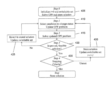
[0050] In operation, referring to FIG. 4, with further reference to FIGS. 2-
3 and 5,
a process 400 for performing topology control using the system 205 includes
the
stages shown. The process 400, however, is exemplary only and not limiting.
The
process 400 may be altered, e.g., by having stages added, changed, removed, or
rearranged. This process often has two objectives: improve cost performance
and
satisfy reliability requirements.
[0051] At stage 405, the transmission topology control 210 initializes the
process
400 by solving the OPF with an initial topology and stores the solution
including
optimal primal and dual variable values. For example, the initial topology can
be the
current topology of the physical electrical system 10 when the process 400
begins.
- 13 -
CA 02865286 2014-08-21
WO 2013/126821
PCT/1JS2013/027488
The optimal primal and dual variables are preferably the output of the OPF,
solved
using a linear programming algorithm. The transmission topology control 210
also
preferably uses an iteration counter to count the number of iterations through
the
process 400. At stage 405 in some embodiments, the iteration counter is set to
zero.
[0052] At stage 405, the transmission topology control 210 also determines
the set
of switches within the physical electrical system 10 whose state can be
changed (e.g.,
opened or closed). In other words, the transmission topology control 210
initializes
the switchable set. The transmission topology control 210 uses switchable set
update
criteria to determine which switches are allowed to change their states in the
current
iteration. For example, the initial switchable set can include all switches
that are able
to change state (e.g., there's no preexisting restriction on the ability of
the switch to
change states).
[0053] The switchable set is initially all lines, and it is preferably
reduced in each
iteration by removing the line(s) indicated by the switching criteria,
regardless of
whether removing the line leads to cost savings, and by also removing lines
that do
not meet the reliability requirements. Once a line is removed from the
switchable set,
in some embodiments it is not reinstated for the remaining iterations of the
process
400. Finally, the switchable set preferably does not include lines that have
negative
upper transmission limits, or positive lower transmission limits.
[0054] Referring to FIG. 5, and as another example, of all the switches 505
shown
in FIG. 5, may initially be selected as the switchable set. After each
iteration of the
process, the switchable set may shrink resulting in a smaller switchable set
that
includes only switches 520 through 525 to include in the switchable set, which
can
then be processed through even further iterations. Additionally, instead of
selecting
individual switches, the transmission topology control 210 can select
individual
transmission lines, which can then be used to determine corresponding
switches.
[0055] At stage 410, the transmission topology control 210 uses the optimal
primal and dual variable values from the OPF solution calculated in stage 405
to
select the individual candidate switch(es) from within the switchable set for
a change
of state. The procedure for selecting the candidate is characterized by the
switching
criteria.
[0056] The switching criteria can select one or more switches (e.g.,
switches 505)
as candidates to change status, and open or close these switches. In some
- 14 -
CA 02865286 2014-08-21
WO 2013/126821
PCMJS2013/027488
embodiments, in each iteration of the process 400, the corresponding metric is
computed and one or more lines are selected as a candidate for opening. The
selection can be made by applying the same criteria in every iteration, by
applying
criteria that are a function of the iteration number, and by applying criteria
that are a
function of the results of previous iterations. The switching criteria itself
can take a
number of forms, including the simple use of OPF primal and dual solution
variables
for the selection, or be based on the result of optimization problems.
[0057] In some
embodiments, at least five sensitivity-based criteria can be used
individually or in combination to determine which lines to open or close: line
profits
criterion, price difference criterion, complete price difference switching
criterion, total
cost derivative criterion and PTDF-weighted criterion. With respect to the
equations
identified below, the following notation is used:
4r:
= Jkistheflowonlinek
'7 7:
= l'erft k are
the nodal prices at the "from" and "to" nodes of
line k
9
= fr0171:k)' k are the nodal voltage angles at the "from" and "to"
nodes of line k
1 ;max 171.01
= imk ek are the shadow prices of line k max and min flow
constraints
= 99 k is the sensitivity of line k flow with respect to a transfer between
the
terminal nodes of line k (power transfer distribution factor)
[0058] The line profits switching criterion selects the most unprofitable
line in the
switchable set as a candidate line for opening, if there is any such line.
Preferably, the
line profit is defined as the product between the line flow and the difference
in prices
between the line's terminal nodes. Unprofitable lines have flow from a higher
price
node to a lower price node. In addition to the most unprofitable line, the
second,
third, fourth, etc. most unprofitable line can also be selected. An exemplary
formula
used in connection with this criterion is:
- 15 -
CA 02865286 2014-08-21
WO 2013/126821
PCMJS2013/027488
k k k
.' (1)
Other profitability criterion can also be considered such as royalty rates,
tax rates,
environmental costs, operating costs, line loss, etc.
[0059] The price difference switching criterion selects the transmission
line in the
switchable set with the largest price difference between its end nodes as the
candidate
for opening or closing. An exemplary formula used in connection with this
criterion
is:
k ;14' ram k (2)
[0060] The complete price difference switching criterion compares the
absolute
value of the price difference of two lines, and selects the line with the
higher value of
such metric as the candidate for a change in state. One of the two lines in
some
embodiments is the line selected by the price difference switching criterion.
The
other line is the line that has the largest price difference among the set of
all open
lines whose closure would lead to a profitable line (e.g., flow from lower
price node
to a higher price node). An exemplary formula used in connection with this
criterion
is:
e,, k ¨ fr
Irumft to kitcJ (3)
[0061] The total cost derivative criterion selects the line from the
switchable set
with the most negative total cost derivative impacts (accounting for the
initial line
flow direction), if any, as the candidate for opening. The total cost
derivative is given
by the difference between the shadow price on the line capacity and the
difference in
prices between the line's terminal nodes, divided by the portion of flow that
does not
flow on the line if a 1 MW transfer is made from one terminal node of the line
to the
other one. An exemplary formula used in connection with this criterion is:
- 16 -
CA 02865286 2014-08-21
WO 2013/126821 PCMJS2013/027488
., x 1,
a in ) _ U.= . )
sIgn(lk) ____________________________________________
1¨ co, (4)
[0062] The PTDF-weighted criterion selects the line with the most negative
power
transfer distribution factor (PTDF) weighted total cost derivative impacts
(accounting
for the initial line flow direction). The PTDF-weighted total cost derivative
is given
by the difference between the shadow price on the line capacity and the
difference in
prices between the line's terminal nodes. An exemplary formula used in
connection
with this criterion is:
1 =
't ( tdllaX õmin)
StgriCrk,A ' 'km* ¨ Pi4 s ¨ (1-174.= k ¨ Irfrim na: k j
(
(5)
[0063] During stage 415, the transmission topology control 210 solves the
OPF
with the updated on/off state of the candidate switch(es) from stage 410.
During this
stage, the transmission topology control 210 generates new sensitivity
parameters
based upon the newly-solved OPF.
[0064] During stage 420, the transmission topology control 210 determines
whether the OPF solution generated in stage 415 i) is feasible, and ii) is an
improvement over the existing OPF solution (i.e., the OPF solution without the
change in state). If the answer is no to either of these items, then the
process
continues to stage 425. Otherwise, the process continues to stage 430.
[0065] Because the metrics employed are based on gradients on the
continuous
flow space, but the amount of flow that can be changed is fixed for every line
(e.g.,
reducing flow on the line to zero by opening it) it is possible that opening a
line
selected by the selection criteria may lead to increased costs or an
infeasible and/or
impossible transmission network topology. In these cases, the process 400
reverts the
transmission network topology to a stored solution and removes the candidate
line
from the switchable set.
[0066] During stage 425, the transmission topology control 210 reverts the
state
of the candidate switch(es) back to the original state, the OPF solution is
reverted to
its previous values, and the switchable set and the iteration counter are
updated. After
stage 425, the process 400 continues back to stage 410.
- 17 -
81781664(86216-7)
[0067] During stage 430, the transmission topology control 210 determines
whether stopping
criteria are met. If so, the process 400 is terminated. Otherwise, the
iteration counter is
increased, the switch(es) states and OPF solutions are stored at stage 435,
and the process returns
to stage 410.
[0068] The stopping criterion may determine the number of iterations
applied, and can
include a number of conditions. For example, the process 400 may stop if no
lines meet the
switching criteria, or if the switchable set is empty. Additionally, the
process 400 can have a
pre-set maximum number of iterations, and/or maximum number of status changes.
Further, the
process 400 may stop if cost reductions exceed a certain threshold, or if the
computation time is
above a pre-defined limit.
[0069] While "cost" has been referred to herein, this term is not limited
to monetary values.
For example, cost in the context of an electrical distribution system can
represent many different
aspects of operation. For example, cost associated with an electrical system
can relate to
monetary concerns, value, environmental concerns, political concerns,
reliability concerns, and
security concerns.
[0070] Other embodiments are within the scope and spirit of the invention.
[0071] The subject matter and functionality described herein can be
implemented in digital
electronic circuitry, or in computer software, firmware, or hardware,
including the structural
means disclosed in this specification and structural equivalents thereof, or
in combinations of
them. The subject matter described herein can be implemented as one or more
computer
program products, such as one or more computer programs tangibly embodied in a
non-
transitory, tangible information carrier (e.g., in a machine-readable storage
device), or embodied
in a propagated signal, for execution by, or to control the operation of, data
processing apparatus
(e.g., a programmable processor, a computer, or multiple computers). A
computer program (also
known as a program, software, software application, or code) can be written in
any form of
programming language, including compiled or interpreted languages, and it can
be deployed in
any form, including as a stand-alone program or as a module, component,
subroutine, or other
unit suitable for use in a computing environment. A computer program does not
necessarily
correspond to a file. A program can be stored in a portion of a file that
holds other programs or
data, in a single file dedicated to the program in question, or in multiple
coordinated files (e.g.,
files that store one or more modules, sub-programs, or portions of code). A
computer program
can be deployed
- 18 -
CA 2865286 2019-06-06
CA 02865286 2014-08-21
WO 2013/126821
PCMJS2013/027488
to be executed on one computer or on multiple computers at one site or
distributed
across multiple sites and interconnected by a communication network.
[0072] The processes and logic flows described in this specification,
including the
method steps of the subject matter described herein, can be performed by one
or more
programmable processors executing one or more computer programs to perform
functions of the subject matter described herein by operating on input data
and
generating output. The processes and logic flows can also be performed by, and
apparatus of the subject matter described herein can be implemented as,
special
purpose logic circuitry, e.g., an FPGA (field programmable gate array) or an
ASIC
(application-specific integrated circuit).
[0073] Processors suitable for the execution of a computer program include,
by
way of example, both general and special purpose microprocessors, and any one
or
more processor of any kind of digital computer. Generally, a processor will
receive
instructions and data from a read-only memory or a random access memory or
both.
The essential elements of a computer are a processor for executing
instructions and
one or more memory devices for storing instructions and data. Generally, a
computer
will also include, or be operatively coupled to receive data from or transfer
data to, or
both, one or more mass storage devices for storing data, e.g., magnetic,
magneto-optical disks, or optical disks. Information carriers suitable for
embodying
computer program instructions and data include all forms of non-volatile
memory,
including by way of example semiconductor memory devices, (e.g., EPROM,
EEPROM, and flash memory devices); magnetic disks, (e.g., internal hard disks
or
removable disks); magneto-optical disks; and optical disks (e.g., CD and DVD
disks).
The processor and the memory can be supplemented by, or incorporated in,
special
purpose logic circuitry.
[0074] To provide for interaction with a user, the subject matter described
herein
can be implemented on a computer having a display device, e.g., a CRT (cathode
ray
tube) or LCD (liquid crystal display) monitor, for displaying information to
the user
and a keyboard and a pointing device, (e.g., a mouse or a trackball), by which
the user
can provide input to the computer. Other kinds of devices can be used to
provide for
interaction with a user as well. For example, feedback provided to the user
can be any
form of sensory feedback, (e.g., visual feedback, auditory feedback, or
tactile
- 19 -
CA 02865286 2014-08-21
WO 2013/126821
PCT/1JS2013/027488
feedback), and input from the user can be received in any form, including
acoustic,
speech, or tactile input.
[0075] The subject matter described herein can be implemented in a
computing
system that includes a back-end component (e.g., a data server), a middleware
component (e.g., an application server), or a front-end component (e.g., a
client
computer having a graphical user interface or a web browser through which a
user can
interact with an implementation of the subject matter described herein), or
any
combination of such back-end, middleware, and front-end components. The
components of the system can be interconnected by any form or medium of
digital
data communication, e.g., a communication network. Examples of communication
networks include a local area network ("LAN") and a wide area network ("WAN"),
e.g., the Internet.
[0076] Further, while the description above refers to the invention, the
description
may include more than one invention.
[0077] What is claimed is:
- 20 -