Note: Descriptions are shown in the official language in which they were submitted.
CA 02865328 2014-08-21
WO 2013/130237
PCT/US2013/025255
IN-SITU AIRFOIL CONTOURING TOOL
BACKGROUND
[0001] The disclosed embodiments generally pertain to a contouring tool.
More
specifically disclosed embodiments pertain to a contouring tool for a leading
or
trailing edge of an airfoil.
SUMMARY
[0002] According to at least one embodiment, an in-situ airfoil contouring
tool is
provided. The tool provides a contouring, recontouring or reconditioning
device
for leading or trailing edges of airfoils used in a variety of industrial
applications.
The tool comprises a housing having an airfoil pathway. A grinding wheel
disposed along the pathway has a desired profile shape of an airfoil edge. A
guide
bearing follows the edge of the airfoil and limits motion of the grinding
wheel in a
first dimension. An edge guide allows motion of the airfoil relative to the
grinding wheel through a second dimension.
[0003] According to at least one exemplary embodiment, the contouring tool
is a
handheld device.
[0004] According to at least one exemplary embodiment, the contouring tool
comprises a motor to drive the grinding wheel.
[0005] According to at least one exemplary embodiment at least one edge
guide is
moveable.
[0006] All of the above outlined features are to be understood as exemplary
only
and many more features and objectives of the invention may be gleaned from the
disclosure herein. Therefore, no limiting interpretation of this summary is to
be
understood without further reading of the entire specification, claims, and
drawings included herewith.
1
CA 02865328 2014-08-21
WO 2013/130237
PCT/US2013/025255
BRIEF DESCRIPTION OF THE ILLUSTRATIONS
[0007] The above-mentioned and other features and advantages of this
invention,
and the manner of attaining them, will become more apparent and the contouring
tool will be better understood by reference to the following description of
embodiments taken in conjunction with the accompanying drawings, wherein:
[0008] Figure 1 is a perspective view of one embodiment of a contouring
tool.
[0009] Figure 2 is an exploded perspective view of the exemplary embodiment
of
the contouring tool.
[0010] Figure 3 is a side view of the engagement of an airfoil passing
through the
exemplary contouring tool wherein an airfoil edge is engaging the grinding
wheel.
[0011] Figure 4 is a side section view of an edge of an airfoil.
[0012] Figure 5 is a section view of a grinding wheel having the
preselected
shape of the desired airfoil.
[0013] Figure 6 is an upper perspective view of the contouring tool
depicted with
an end plate removed to depict the guides therein.
[0014] Figure 7 is a section view of the contouring tool showing
embodiments of
the various guides bearings, edge guides, and grind wheel.
[0015] Figure 8 is an exemplary graph depicting an eroded airfoil edge
which
falls outside acceptable tolerances.
[0016] Figure 9 is an exemplary graph depicting the contoured airfoil edge
of
Figure 8 after contouring.
DETAILED DESCRIPTION
[0017] Referring initially to Figures 1 through 9, embodiments of a
contouring
tool are shown and described wherein the tool may be utilized to contour an
edge,
for example leading edge, of an airfoil, which typically erodes due to
exposure to
dirt, water and air over time which all erode the desired shape of the airfoil
over
time. The terms contouring and recontouring are used interchangeably as it
should be understood from this disclosure that the tool may be used for both
new
2
CA 02865328 2014-08-21
WO 2013/130237
PCT/US2013/025255
airfoil edge contouring or recontouring of an existing airfoil edge. Further
the
term leading edge is used thought this disclosure and is descriptive of merely
one
type of airfoil edge which may be contoured. Trailing edges may also be
contoured and are within the scope of this disclosure as well. Thus the term
leading should not be considered limiting but merely exemplary.
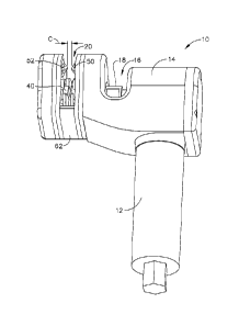
[0018] Referring initially to Figure 1, a perspective view of the
contouring tool 10
is depicted. The structure includes a handle 12 and a housing or cover 14. The
tool 10 may be handheld or alternatively may be non-handheld such as attached
to
a fixture, jig or a robot, all of which being non-limiting examples. The
instant
embodiment utilizes a motor (not shown) in the handle 12 and a right angle
drive
structure operably connected to the motor to drive a grinding structure, such
as a
grinding wheel, 40. A main drive shaft 42 (Figure 2) is perpendicular to the
motor axis (not shown) and the main drive shaft transmits rotation from the
motor
to the grinding wheel 40. Although this structure is shown and described, a
right
angle drive is not necessary for use of this invention and alternative
embodiments
may be used. Thus, the embodiment described herein should not be considered
limiting. Additionally, the description of a driven grinding structure should
not be
considered limiting as stationary or non-driven grinding structures are also
believed to be within the scope of the instant invention.
[0019] The housing 14 includes a chuck access 16 wherein a chuck 18 is
positioned. The chuck 18 provides a drive connection between the motor (not
shown) and the drive shaft 42 of the grinding wheel, described further herein.
The housing 14 includes an airfoil pathway 20 wherein various guides and the
grinding structure are positioned. An airfoil 92 (Figure 4) is positioned
within the
pathway 20 and positioned by the guides so that the exemplary airfoil edge 94
(Figure 4) is ground to the proper shape and at the proper location of the
airfoil.
[0020] A clearance C is represented as a distance between guide bearings
50, 52.
The guide bearings 50, 52 inhibit rocking or side-to-side motion of the edge
94
within the pathway 20 and additionally inhibit use of the tool with airfoil
which
3
CA 02865328 2014-08-21
WO 2013/130237
PCT/US2013/025255
are of too large a size for the tool 10. The guide bearings may be fixed,
spring
loaded or otherwise biased, adjustable or any combination thereof to
accommodate multiple sizes and shapes of airfoils.
[0021] Referring now to Figure 2, the contouring tool 10 is shown in an
exploded
perspective view for identification and explanation of the multiple guides,
bearings and at least one grinding wheel utilized therein. Adjacent handle 12
is
an actuator 22 which actuates the motor (not shown). The motor may be various
types of driving mechanisms including, but not limited to, electric motor,
hydraulic motor, or pneumatic motor. The motor drives a grinding structure 40,
such as for example a grind wheel 40, and a transmission 24 including the
chuck
18. The chuck 18 operably connects a drive shaft 42 to the grind wheel 40. The
grind structure 40 may have an RPM in the range of between 0 and 20,000
revolutions per minute (RPM). Accordingly, the motor may have a range of
between 0 and 20,000 RPM with a transmission suited to provide the desired
speed or RPM at the grinding wheel 40. At an upper end of the handle, the
chuck
18 and transmission may be at least partially covered by the housing 14 and a
housing plate 26. It should be understood that the housing may or may not
include a portion that defines at least some portion of the handle 12. The
housing
or cover 14 provides access by way of the chuck access 16 to the chuck 18 for
connection or disconnection of the main drive shaft 42 to the motor within the
handle 12. The housing 14 includes a drive shaft passage 28 allowing
connection
or engagement with the chuck 18.
[0022] The grinding structure 40 may be formed of a tool steel or other
high
strength metal with a cubic boron nitride abrasive material. However, other
materials may be utilized and the exemplary materials should not be considered
limiting. The airfoils may be formed of titanium and alternatively may be
formed
of specialty alloys, such as an austenitic nickel-chromium-based alloy which
is
sold under the trade name INCONEL. Other non-metallic airfoils may be utilized
4
CA 02865328 2014-08-21
WO 2013/130237
PCT/US2013/025255
with the tool and any reference to an airfoil should not be considered limited
to
metallc structures.
[0023] Moving to the right-hand side of the figure, the main drive shaft 42
is
shown with broken line extending to the chuck 18. Adjacent the main shaft 42
is
a first mounting plate 44 having apertures for multiple fasteners and shaft
aperture
allowing passage of the drive shaft 42. The mounting plate 44 includes
aperture
46 for positioning of block 48 therethrough. The block 48 is a mount for the
guide bearing 50. Adjacent the bearing block 48 is a second mounting plate 60.
The second mounting plate 60 includes a block aperture corresponding in
position
to the aperture 46 and allowing a portion of the block 48 to pass therethrough
so
that the guide bearing 50 is exposed to pathway 20. Opposite a center spacer
62
are opposed third and fourth mounting plates 70, 72 and an opposed cover plate
74. These structures attach to the housing 14 and define the pathway 20.
[0024] The guide bearings 50, 52 are oriented so that pivot shafts 56, 58
are
substantially transverse to the drive shaft 42 of the grinding wheel 40. The
guide
bearing 50, 52 position the airfoil laterally within the airfoil pathway 20
(Figure
1) and limit or inhibit movement in the axial direction of the main driveshaft
42,
as well as locking or pivoting motion along the upper edge of the airfoil 92
where
a grinding may occur. The guide bearings 50, 52 may both be fixed or
alternatively one or both bearings 50, 52 may be movable to vary with varying
widths of airfoils.
[0025] Referring above the center spacer 62 are airfoil edge guides 80, 82,
for
example leading edge guides. The airfoil edge guides 80, 82 allow motion in a
direction which is generally transverse to the drive shaft 42 and travel along
the
edge of the airfoil 92. The guides 80, 82 have pivot axes which are parallel
to the
main drive shaft 42. Thus, the axes of the airfoil edge guide 80, 82 are
parallel to
the axis of the grinding wheel 40. The guides 80, 82 define two points along
the
airfoil edge of the airfoil 92 between which the grinding wheel 40 is
contouring or
recontouring at any moment during operation. Access to guide bearings 50, 52
CA 02865328 2014-08-21
WO 2013/130237
PCT/US2013/025255
limit motion in a first dimension and airfoil edge guides 80, 82 allow for
motion
in a second dimension generally perpendicular there the first dimension. One
of
the edge guides 80, 82 is designed to float or move to allow for some rocking
motion of the grinding wheel 40 in the direction of the airfoil edge while
moving
along the edge 94 of the airfoil 92. However, such rocking motion is not
considered to be limiting as both edge guides 80, 82 may be fixed and
therefore
inhibiting such rocking motion.
[0026] Referring now to Figure 3, an exemplary edge 94 of an airfoil 92 is
shown
in section as indicated by the cross-hatch in the view. The tool 10 moves into
or
out of the page, in the view depicted. The grinding wheel 40 is shown having a
central profile 90 which matches the desired or preselected shape of the
airfoil.
More specifically, the edge 94 of the airfoil 92 is disposed within the
profile 90 of
the grinding wheel 40 to grind the edge 94 as the tool passes there along.
According to the instant embodiment the grinding wheel 40 is formed of two
wheels which are placed together in order to form the airflow profile. The
grinding wheel 40 may alternatively be formed of a single grinding wheel
structure having the desired profile showed therein or may be formed to more
pieces which are joined together along the drive shaft 42 (Figure 2) in order
to
provide the preselected airfoil edge shape.
[0027] The exemplary airfoil 92 is shown with a camber or twist causing one
side
of the airfoil to appear wider than the other. As seen in this view, the guide
bearing 50, 52 limit motion or pivoting at the edge 94 of the airfoil 92 so
that the
edge shape is not inappropriately ground in an undesired location of the
airfoil 92.
[0028] As also shown in Figure 3, the further guide wheel 82 is positioned
over
the edge 94 such that the grinding wheel 40 and profile 92 form the
preselected
airfoil shape on the edge thereof The edge guide 82 allows for motion into the
page while the guide bearing 50, 52 limit motion in a transverse direction.
6
CA 02865328 2014-08-21
WO 2013/130237
PCT/US2013/025255
[0029] Referring now to Figure 4, a section view of a turbine engine
airfoil 92 is
depicted. The shape of the airfoil 92 is after the tool 10 is used and the
eroded
areas are removed by way of the grinding wheel 40 and profile 90 therein.
[0030] Referring now to Figure 5, a section view of the exemplary grinding
structure 40 is depicted comprising a first portion 87 and a second portion
88.
Alternate embodiments should be considered within the scope of the
embodiments wherein the grinding wheel 48 is formed of a single piece rather
than the two or more portions. A profile 90 extends about the axis of the
grind
wheel 40 and an aperture extends through the grinding wheel 40 for positioning
of
the drive shaft 40 therethrough. The grinding wheel 40 rotates about this
shaft 42
and shaft aperture. The profile 90 may be symmetrical or non-symmetrical
depending on the airfoil edge shape needed.
[0031] Referring now to Figure 6, the contouring tool 10 is shown in an
upper
perspective view. With cover plate 74 removed, the edge guides 80, 82, the
grinding wheel 40 and the guide bearings 50, 52 are easily visible adjacent
the
center spacer 62. Disclosed in this view, the airflow will be positioned
within the
pathway or passage 20 between the guide bearings 50, 52. These bearings
inhibit
movement to the left or right, as shown in the figure. The edge guides 80, 82
ride
along the edge, for example, leading edge 94 of the airfoil 92 (Figure 4) and
the
edge 94 of the airfoil is positioned in the grinding profile 90 of the
grinding
structure 40 so that the airfoil 92 conforms to the profile 90 shape placed
therein.
Thus, it should be understood that the preselected shape of the profile 90 may
be
duplicable to a specific airfoil or multiple airfoils by merely adjusting the
guides,
bearings and grinding structure. However, whatever shape is desired should be
applied to the proper or corresponding airfoil. Figure 6 further depicts a
floating
block 36 which retains ends of shafts 86 and which allows the edge guide 82 to
move. The movement allows for some limited rocking motion by the tool 10
during movement along the edge 94 of the airfoil 92 in a direction extending
between the edge guides 80, 82. In operation, the edge guide 82 will move
7
CA 02865328 2014-08-21
WO 2013/130237
PCT/US2013/025255
toward or away from the center spacer 62 when the rocking motion occurs while
shaft 84 and guide 80 remain fixed. Alternatively, the block 36 may be fixed
so
that shaft 86 cannot move and edge guide 82 is also fixed inhibiting the
rocking
motion.
[0032] Referring now to Figure 7, the floating blocks 36, 38 are shown and
depict
adjacent material sectioned for the clear perspective view. A slot 34 is
positioned
in the mounting plate 60, 72. The slot 34 allows vertical movement of the
floating blocks 36, 38 so that shaft 86 can move in the directions shown by
the
arrows on the floating blocks 36, 38. As shown in the figure, the pathway 20
allows for positioning upwardly through pathway 20 between the guide bearing
50, 52 and into the adjacent grinding wheel 40. The airfoil edge 94 is
positioned
in the edge guides 80, 82 and the, for example, leading edge may be moved in
the
direction into or out of the page while the grinding wheel rotates and grinds
the
edge 94 of the airfoil 92 therein. The guide bearings 50, 52 inhibit left
right
motion or rocking motion along the edge of the airfoil so that the guide
bearing
50, 52 limits motion in a first direction and the edge guides allow motion in
a
substantially transverse direction.
[0033] Referring now to Figures 8 and 9, first and second graphs are shown
comparing an airfoil edge profile prior to grinding and subsequent to grinding
with the contouring tool, respectively. These graphical representations depict
the
change in shape of the edge due to erosion and due to use of the re-contouring
tool. In Figure 8, a first line 110 represents a minimum tolerance of the
shape of
the airfoil edge. A second parallel line 120 represents a maximum tolerance. A
third broken line 122 depicts a nominal shape for an airfoil edge. A fourth
line
124 indicates the flattened or otherwise misshaped portions where erosion has
taken a detrimental toll on the shape of the edge. This results in loss of
proper
shape and decreased engine thrust for aircraft engines despite periodic
overhauls
of the engine structure.
8
CA 02865328 2014-08-21
WO 2013/130237
PCT/US2013/025255
[0034] Following use of the exemplary embodied tool 10, and with reference
to
Figure 9, the line 124 representing the shape of the edge 94 more closely
matches
the nominal shape of line 122. As a result, the shape of the edge is within
the
minimum and maximum tolerances 110, 120 and more closely approximates the
nominal desired shape. As a result, the thrust provided by this contoured or
recontoured airfoil will be increased as opposed to that in Figure 8 due to
the
erosion damage.
[0035] While multiple inventive embodiments have been described and
illustrated
herein, those of ordinary skill in the art will readily envision a variety of
other
means and/or structures for performing the function and/or obtaining the
results
and/or one or more of the advantages described herein, and each of such
variations and/or modifications is deemed to be within the scope of the invent
of
embodiments described herein. More generally, those skilled in the art will
readily appreciate that all parameters, dimensions, materials, and
configurations
described herein are meant to be exemplary and that the actual parameters,
dimensions, materials, and/or configurations will depend upon the specific
application or applications for which the inventive teachings is/are used.
Those
skilled in the art will recognize, or be able to ascertain using no more than
routine
experimentation, many equivalents to the specific inventive embodiments
described herein. It is, therefore, to be understood that the foregoing
embodiments are presented by way of example only and that, within the scope of
the appended claims and equivalents thereto, inventive embodiments may be
practiced otherwise than as specifically described and claimed. Inventive
embodiments of the present disclosure are directed to each individual feature,
system, article, material, kit, and/or method described herein. In addition,
any
combination of two or more such features, systems, articles, materials, kits,
and/or
methods, if such features, systems, articles, materials, kits, and/or methods
are not
mutually inconsistent, is included within the inventive scope of the present
disclosure.
9
CA 02865328 2016-02-16
256147
[0036] Examples are used to disclose the embodiments, including the best
mode,
and also to enable any person skilled in the art to practice the apparatus
and/or
method, including making and using any devices or systems and performing any
incorporated methods. These examples are not intended to be exhaustive or to
limit the disclosure to the precise steps and/or forms disclosed, and many
modifications and variations are possible in light of the above teaching.
Features
described herein may be combined in any combination. Steps of a method
described herein may be performed in any sequence that is physically possible.
[0037] All definitions, as defined and used herein, should be understood to
control over dictionary definitions and/or ordinary meanings of the defined
terms. The indefinite articles "a" and "an," as used herein in the
specification
and in the claims, unless clearly indicated to the contrary, should be
understood
to mean "at least one." The phrase "and/or," as used herein in the
specification
and in the claims, should be understood to mean "either or both" of the
elements
so conjoined, i.e., elements that are conjunctively present in some cases and
disjunctively present in other cases.
[0038] It should also be understood that, unless clearly indicated to the
contrary,
in any methods claimed herein that include more than one step or act, the
order of
the steps or acts of the method is not necessarily limited to the order in
which the
steps or acts of the method are recited.
[0039] In the claims, as well as in the specification above, all
transitional phrases
such as -comprising," "including," "carrying," "having," "containing,"
"involving," "holding," "composed of," and the like are to be understood to be
open-ended, i.e., to mean including but not limited to. Only the transitional
phrases "consisting of' and "consisting essentially of' shall be closed or
semi-
closed transitional phrases, respectively.