Note: Descriptions are shown in the official language in which they were submitted.
CA 02865469 2014-08-25
WO 2013/131178
PCT/CA2013/000211
COUNTERWEIGHTED PUMP JACK
WITH REVERSIBLE MOTORS
FIELD OF THE DISCLOSURE
The present disclosure relates to well pumping units for operating rod-
actuated
downhole oil well pumps and the like.
BACKGROUND
In common methods for producing fluids from a well drilled into a petroleum-
bearing subsurface formation, a string of steel production tubing is
positioned in the
wellbore and extends from the subsurface production zone up to a wellhead at
the
surface. A downhole pump is disposed within the production tubing in the
production
zone to raise well fluids (e.g., oil, gas, formation water) to the surface, by
reciprocating
vertical movement of a travelling valve incorporated into the pump. The
travelling valve
is reciprocated by a pump rod string (or "sucker rod" string) extending upward
within the
production tubing to the wellhead where it connects to a "polished rod"
extending
upward through a wellhead tee and stuffing box to connect to a pumping unit.
This type
of pump is commonly referred to as a positive-displacement pump or "sucker rod
pump".
Various types of well pumping units have been developed for operating
positive-displacement downhole pumps, with the most common type being a "pump
jack" comprising a walking beam mechanism that reciprocates the sucker rod
string
connected to the downhole pump, by means of a drive train comprising an
electric motor
or internal combustion engine, a gear reduction mechanism, and a braking
system. The
walking beam style of pumping unit is large, heavy, and expensive to build. If
the single
cable connecting the free end of the walking beam to the polished rod at the
upper end of
the pump rod string should break, the pump rod string will fall
uncontrollably, damaging
the well head and possibly losing the entire rod string into the well hole,
entailing costly
repairs and creating a safety hazard.
- 1 -
CA 02865469 2014-08-25
WO 2013/131178
PCT/CA2013/000211
It is known to modify a walking beam pump jack to incorporate a counterweight
system in order to reduce the total weight that needs to be lifted by the pump
jack's drive
system. During the upstroke of a downhole pump, the pump jack must lift the
total
weight of the sucker rod string plus the column of well fluids above the
downhole
pump's travelling valve. For example, for a rod string that weighs 15,000
pounds
(including the travelling valve) and is required to lift a fluid column
weighing 10,000
pounds, the pump jack will need to lift a total of 25,000 pounds on each
upstroke. At the
top of each upstroke, the pump jack's drive system must be disengaged to
initiate a
downstroke allowing the travelling valve to fall to the bottom of the well. On
the
downstroke, the 15,000-pound rod string is essentially in a controlled
freefall through the
liquid in the production tubing. Accordingly, the pump jack apparatus needs to
incorporate a robust braking system to regulate the speed of the downstroke.
In a counterweighted pump jack system, the counterweight ideally corresponds
to
the weight of the rod string plus half the weight of the fluid column to be
raised. In the
example above, the counterweight would ideally weigh 20,000 pounds (i.e.,
15,000
pounds plus 1/2 of 10,000 pounds), such that the net required lifting force
on the pump's
upstroke would be only 5,000 pounds. At the top of the upstroke, there would
be a net
downward force of 5,000 pounds acting on the counterweight -- i.e., 20,000
pounds for
the counterweight minus 15,000 pounds for the rod string (there being no fluid
column
load on the downstroke). Therefore, the pump jack's drive system requires a
net lifting
capacity of only 5,000 pounds -- i.e., to lift the rod string and fluid column
on the pump's
upstroke, and to lift the counterweight on the pump's downstroke. This is in
contrast to a
non-counterweighted pump jack, which lifts only on the upstroke, but the
required lifting
capacity is dramatically reduced, as are the braking requirements.
Because a counterweighted pumping unit will typically need to lift on both the
upstroke and the downstroke of the downhole pump, the unit's drive system must
be
reversible. The drive systems of most known pump jacks use conventional
electric
motors, which rotate in only one direction. Therefore, the use of such motors
in
counterweighted pumping units requires a reversing mechanism of some type. A
suitable
- 2 -
CA 02865469 2014-08-25
WO 2013/131178
PCT/CA2013/000211
control system is provided to alternate the pump stroke direction at the end
of each
upstroke or downstroke.
One example of a prior art counterweighted pumping unit driven by an electric
motor is the Rotaflex unit manufactured by Weatherford International Ltd.,
of
Houston, Texas. The Rotaflex unit has a vertical tower structure and an
electric motor
at the base of the tower. A gearbox is fitted to the motor's output shaft, and
a drive
sprocket is mounted to the gearbox. A continuous drive chain is trained around
the drive
sprocket and around an idler sprocket mounted in an upper region of the tower.
A
counterweight is connected to a selected link in the drive chain such that the
counterweight will move vertically with the drive chain. A mechanical
reversing
mechanism is provided to alternate the travel direction of the drive chain and
in turn the
travel direction of the counterweight.
A discontinuous load belt is deployed over an idler roller mounted at the top
of
the tower, with one end of the load belt being connected to the counterweight
and with
the other end of the counterweight being connected to the polished rod of a
sucker rod
string associated with a wellhead. The rotational axis of the idler roller is
transverse to
the rotational axes of the drive chain sprockets, not parallel. By virtue of
the connection
of the counterweight to both the drive chain and also to the load belt,
actuation of the
electric motor causes the load belt to raise either the rod string or the
counterweight,
depending on the direction of travel of the drive chain (as controlled by the
drive
system's mechanical reversing mechanism).
The Rotaflex unit thus provides the benefits of counterweighting in
conjunction
with a unidirectionally-rotating electric primary drive motor, but has the
drawback of
requiring complex mechanical apparatus in order to provide the necessary
lifting capacity
on both the upstroke and downstroke of the downhole pump being actuated by the
unit.
Particular examples of this mechanical complexity include the need for a gear
reducer at
the electric drive motor's output shaft (which rotates much faster than the
drive sprocket),
the specialized mechanical reversing mechanism, and the need for both a drive
chain
- 3 -
CA 02865469 2014-08-25
WO 2013/131178
PCT/CA2013/000211
arrangement for reciprocating the counterweight plus a load belt arrangement
for
transferring lifting force to the rod string during the upstroke of the
downhole pump.
U.S. Patent No. 4,226,404 (Zens) discloses a counterweighted pumping unit that
uses a reversible hydraulic motor actuated by a hydraulic pump. The hydraulic
motor is
directly coupled to a drum so as to rotate the drum about a horizontal axis. A
pair of
sheaves are provided, one on either side of the drum, with rotational axes
generally
parallel to the rotational axis of the drum. A first traction cable is fixed
at one end to a
first selected point on the perimeter of the drum and trained over a first one
of the
sheaves, with its other end being connected to a counterweight assembly. A
second
traction cable is fixed at one end to a second selected point on the perimeter
of the drum
and trained over the second sheave, with its other end being connected to a
rod string
associated with a wellhead. Rotation of the drum in a first direction will
result in the rod
string being raised and the counterweight being lowered; rotation of the drum
in the
opposite direction will result in the counterweight being raised and the rod
string being
lowered.
The illustrated embodiments of the Zens apparatus include one or more load
cables trained over the sheaves, and connected at their opposite ends to the
counterweight
and to the rod string. The load cables do not engage the drum and therefore
are not
driven, but they serve to share the counterweight and rod string loads,
preferably equally.
To prevent uncontrolled lateral migration of the traction cables and load
cables during
operation of the apparatus, as well as interference between these cables, the
perimeter
surface of the drum is formed with a continuous helical groove for receiving
and training
the traction cables, and the perimeter surfaces of the sheaves are formed with
parallel
annular grooves for receiving and training the load cables.
Due to the helical groove in the drum, the lateral positions of the traction
cables at
and relative to the drum will shift (in a direction parallel to the drum's
rotational axis) as
the drum rotatingly oscillates from upstroke to downstroke. Because the
lateral positions
of the traction cables at the sheaves does not change during operation of the
apparatus,
the lateral shifting of the traction cables at the drum will cause a fleet
angle to develop on
- 4 -
CA 02865469 2014-08-25
WO 2013/131178
PCT/CA2013/000211
each oscillation (i.e., the traction cables, unlike the load cables, will not
remain
perpendicular to the rotational axes of the drum and sheaves). This generally
undesirable
condition is overcome in the Zens apparatus by providing an ancillary
mechanism for
tilting the axis of the drum as necessary to compensate for the fleet angle(s)
that would
otherwise develop.
The Zens apparatus thus provides an example of a counterweighted pumping unit
that avoids the need for gear reduction components and reversing mechanisms as
in the
Rotaflexe unit. However, it too has disadvantageous mechanical complexities,
including
the requirement for the large drum associated with the traction cables, the
"highly
desirable" load cables in addition to the traction cables, and the large
sheaves also
required for the traction cables and load cables. It is stated in the Zens
patent that the size
of the sheaves can be reduced by using additional cables; however, providing
additional
traction cables and load cables introduces additional complexity. A further
drawback of
the Zens apparatus is the inherent problem of fleet angles developing with
respect to the
traction cables, which is addressed by introducing further mechanical
complexity in the
form of a mechanism for constantly tilting the axis of the drum to keep the
fleet angle
equal to essentially zero.
For the foregoing reasons, there is a need for improved counterweighted
pumping
units having less mechanically complex drive systems than conventional
counterweighted
pumping units.
BRIEF SUMMARY
The present disclosure teaches a counterbalanced pump jack comprising a
counterweight assembly from which a pump rod string can be suspended. One or
more
(and typically at least two) reversible drive motors are mounted on an
elevated platform.
In preferred embodiments, the reversible drive motors are hydraulic motors.
For each
motor, an elongate, flexible, non-continuous connector (such as, without
limitation, a
drive belt or drive chain) is trained over a drive sheave (or drive sprocket)
that is rotated
by the motor. One end of each connector is connected to the counterweight
assembly,
and the other end is connected to the pump rod string by means of a suitable
rod-
- 5 -
CA 02865469 2014-08-25
WO 2013/131178
PCT/CA2013/000211
supporting apparatus (referred to herein a "rod-clamping device", which term
is intended
to encompass all types of apparatus suitable for connecting to and supporting
a pump rod
string). The counterweight is of suitable mass to offset a selected percentage
of the total
weight of the pump rod string and the weight of the fluid column being lifted
by the
downhole pump.
On the upstroke, the drive motors have to lift only the weight of the pump rod
string and the fluid column, minus the weight of the counterweight. At the top
of the
upstroke, the drive motors reverse direction, initiating a downstroke during
which the
pump rod string travels downward to its lowermost position. At that point, the
drive
motors reverse direction, thus initiating the next upstroke.
The use of multiple drive motors working together allow for multiple flexible
connectors to be attached to the rod-clamping device. For optimal safety and
reliability,
the flexible connectors are preferably selected or designed with a safety
factor sufficient
to ensure that the pump rod string cannot fall even if all but one of the
flexible connectors
should break.
Accordingly, in one aspect the present disclosure teaches a well pumping unit
comprising an elevated platform supported by a support structure, with two or
more
reversible drive motors mounted on the platform. Each drive motor has a
rotating output
shaft (alternatively referred to as a drive shaft) operatively connected to a
rotatable drive
component such that actuation of the drive motor will cause the rotatable
drive
component to rotate at the same rate as the drive shaft (in other words, a
"direct drive"
arrangement, with no associated speed reduction means).
For each drive motor, an elongate flexible drive element (which could be, by
way
of non-limiting example, a drive belt such as a synchronous belt, or a drive
chain) is
trained over the associated rotatable drive component (which could be, by way
of non-
limiting example, a synchronous belt pulley or a drive chain sprocket,
depending on the
type of flexible drive element being used. The flexible drive element is
discontinuous,
with a first end connected to a counterweight assembly that is vertically
movable below
- 6 -
CA 02865469 2014-08-25
WO 2013/131178
PCT/CA2013/000211
the platform, and a second end that is connectable to a pump rod string
associated with a
wellhead.
Suitable power and control systems are provided to control the operation of
the
drive motors. In one sense the power system and the control system may be
considered
as discrete systems. However, since these systems will typically function in
direct and
substantially constant interaction with each other, in a practical sense they
may also be
considered as constituting a unified power and control system.
The term "power system" as used in this patent document is referable to one or
more components by means of which energy is provided to the reversible drive
motors to
produce an output torque. In the case of a hydraulic power system, such
components
would typically include a prime mover (such as, without limitation, a gas
engine or an
electric motor), a hydraulic pump driven by the prime mover, and a hydraulic
fluid
reservoir. Locating the hydraulic motors on an elevated platform as disclosed
herein
allows the prime mover(s), the hydraulic pump(s), the hydraulic fluid
reservoir, and/or
other related components to be positioned on the ground, with hydraulic fluid
lines being
routed between the hydraulic pumps and the hydraulic motors, thus minimizing
the
components that need to be provided on the platform and thereby facilitating
efficient
power system service and maintenance.
The term "control system" as used in this patent document is referable to a
set of
components by means of which the pump rod's stroke length, speed, direction of
travel
(i.e., upstroke or downstroke) are regulated in accordance with selected
operational
criteria. Persons skilled in the art will appreciate that control systems
operationally
suitable for use with pumping units in accordance with the present disclosure
can be
provided in many alternative ways, using well-known technologies, so there are
no
particular components that necessarily would form part of all such control
systems.
In a broad sense, the control system comprises a means or method by which
information regarding the state (e.g., speed and direction) of the pump rod
string and/or
counterweight is received and then synthesized, and it will be the technical
nature and
characteristics of the selected means or method that will ultimately dictate
the particular
- 7 -
CA 02865469 2014-08-25
WO 2013/131178
PCT/CA2013/000211
components required for a particular embodiment of the control system. To
provide one
non-limiting example, the transfer of information/data regarding the state of
the pump rod
and/or the counterweight assembly could alternatively be effected through
hydraulic,
electric, mechanical, pneumatic, or magnetic means.
One aspect of the control system's function is to alternate the rotational
directions of the drive motors as required for operation of the well pumping
unit, such
that on the downstroke of the downhole pump to which the rod string is
connected, all of
the flexible drive elements will be lifting the counterweight (i.e., all of
their first ends will
be moving upward), and on the upstroke all of the flexible drive elements will
be lifting
the rod string (i.e., all of their second ends will be moving upward).
Depending on the
selected number and arrangement of drive motors, this may entail that one or
more of the
drive motors at any given time will be rotating in a direction opposite to the
rest of the
drive motors. For purposes of clarity in the context of this patent
specification, the drive
motors may be referred to as operating in a "first cooperative sense" when
they are all
rotating so as to lift the counterweight, and in a "second cooperative sense"
when they are
all rotating so as to lift the rod string.
In pumping units in accordance with the present disclosure, the flexible drive
elements serve as both drive means and load-carrying means, in contrast to
prior art
counterweighted pump units that use separate flexible drive elements (such as
cables,
chains, or belts) plus separate flexible load-carrying elements (such as
cables, chains, or
belts). Drive chains and drive belts of suitable strength and reliability are
readily
available in various forms. Synchronous belts, which have teeth on one or both
sides for
meshing engagement with complementary synchronous belt pulleys, are well known
(one
particularly common use of synchronous belts being for timing belts in
automobiles), and
can reliably carry large tensile loads, particularly when reinforced with
Kevlar or other
reinforcing materials.
In preferred embodiments, the drive motors and their associated rotatable
drive
components are arranged on the platform such that the flexible drive elements
carry
substantially equal portions of the weight of the counterweight and the rod
string. This
- 8 -
CA 02865469 2014-08-25
WO 2013/131178
PCT/CA2013/000211
arrangement will be advantageous in that all of the drive motors and all of
the flexible
drive elements will have the same power or load-carrying requirements, with
resultant
benefits in terms of manufacturing and maintenance costs and efficiencies.
However, this
is not an essential requirement; for some operational situations, it might be
necessary or
desirable for the various components of the pumping unit drive system to be
arranged
such that they carry unequal shares of the lifted loads.
Well pumping units in accordance with the present disclosure may be used on
vertical wells, but can also be adapted for use on well that intercept the
ground surface at
an angle.
In certain embodiments, the counterweight assembly defines a vertical passage
through which the second ends of the flexible drive elements can pass for
connection to
the pump rod string, such that the center of gravity of the counterweight is
concentric
with the pump rod string. In other embodiments, the counterweight assembly is
laterally
offset from the pump rod string.
Optionally, the well pumping unit may be provided with a safety cage enclosing
at least a portion of the vertical support structure. Other optional safety
features include
counterweight lockout means and polished rod lockout means, for locking the
vertical
positions of the counterweight assembly and the rod string in order to protect
workers
from injury that otherwise might occur due to unintended counterweight and rod
string
movements during pumping unit maintenance or other activities,
BRIEF SUMMARY OF THE DRAWINGS
Embodiments in accordance with the present disclosure will now be described
with reference to the accompanying Figures, in which numerical references
denote like
parts, and in which:
FIG. 1 is an elevational perspective view of a first embodiment of a
counterweighted pump jack, shown with the counterweight assembly in a
raised position, and with the pump rod string near the bottom of its
doumstroke.
- 9 -
CA 02865469 2014-08-25
WO 2013/131178
PCT/CA2013/000211
FIG. 2 is a top view of a counterweighted pump jack as in FIG. 1, showing
multiple drive motors attached to bearing blocks and drive sheaves via drive
shafts.
FIG. 3 is an oblique top view of the equipment platform of a counterweighted
pump jack as in FIG. 1, shown with exemplary embodiments of
counterweight lockout means and rod string lockout means installed.
FIG. 4 is a perspective view of a second embodiment of a counterweighted
pump jack in accordance with the present disclosure.
FIG. 5 is a perspective view of a third embodiment of a counterweighted
pump jack adapted for operation in association with an angled wellbore.
FIG. 6 is a perspective view of a pump jack similar to the pump jack shown
in FIG. 5, but with an alternative embodiment of the drive system.
FIG. 7 is a perspective view of a fourth embodiment of a counterweighted
pump jack in which the counterweight is laterally offset from the wellbore in
association with which the pump jack has been installed, shown with the
counterweight assembly in a raised position, and with the rod string near the
bottom of its downstroke.
DETAILED DESCRIPTION
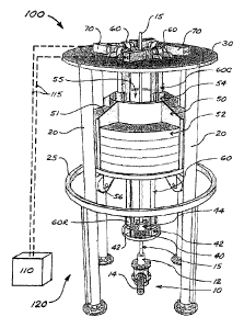
FIGS. 1-3 illustrate a first embodiment 100 of a well pumping unit in
accordance
with the present disclosure. Pumping unit 100 comprises a support structure
120 that
may be positioned over a wellhead 10 associated with a wellbore. Wellhead 10
will
typically include a stuffing box 12 through which and upward from which
extends a
polished rod 15 associated with a pump rod string connected to a downhole pump
(not
shown) disposed within a production tubing string installed in the wellbore.
Wellhead 10
also includes a flow tee 14 for drawing off fluids produced from the well.
In FIGS. 1-3, support structure 120 is shown as comprising a plurality of
vertical
columns 20, with a perimeter support member 25 connecting columns 20 at about
mid-
height. This depiction is solely for conceptual illustrative purposes; the
configuration of
- 10 -
CA 02865469 2014-08-25
WO 2013/131178
PCT/CA2013/000211
support structure 120 for a given application will be a matter of design
choice, and
embodiments of well pumping units in accordance with the present disclosure
are not
limited to support structures as shown in any illustrated embodiment or to
support
structures of any other particular configuration.
An equipment platform 30 is provided at the top of or in an upper region of
support structure 120. In FIGS. 1-3, platform 30 is shown as a generally solid
platform
(with openings as needed for functional purposes described later herein), but
this is by
way of non-limiting example only. In alternative embodiments, platform 30
could have
an open-grated surface or could comprise an open structure.
As most clearly shown in FIG. 2, a plurality of drive motors 70, each having
an
output drive shaft 72, are mounted on platform 30 in a generally symmetrical
pattern
around a central opening 32 provided in platform 30 for passage of polished
rod 15.
Each drive shaft 72 operatively engages a rotatable drive component 80 (shown
in the
Figures in the form of a drive sheave) in association with a pair of suitable
bearings 82.
Trained in operative engagement over each rotatable drive component 80 is an
elongate
flexible drive element 60 (shown in the Figures in the form of a drive belt)
having a first
end 60C and a second end 60R, both of which extend downward on either side of
the
associated rotatable drive component 80 through a secondary opening or
openings 35 in
platform 30.
As best seen in FIG. 1, the first ends 60C of all flexible drive elements 60
are
connected to a counterweight assembly 50 by means of suitable counterweight
connection components 54. In the embodiment shown in FIG. 1, counterweight
assembly
50 comprises a cradle structure 51 of generally toroidal configuration with a
central
vertical opening 55. Cradle 51 is configured to receive removable arcuate
counterweight
plates 52, and is disposed within support structure 120 so as to be vertically
movable
therewithin. Also shown is vertical guide means (shown in the form of guide
rollers 56
engageable with columns 20) for guiding the vertical movement of counterweight
assembly 50 within support structure 120. This illustrated configuration of
counterweight
assembly 50 is by way of non-limiting example only, and counterweight assembly
50 can
be provided in alternative configurations to suit specific operational
requirements.
- 11 -
CA 02865469 2014-08-25
WO 2013/131178
PCT/CA2013/000211
Also as seen in FIG. 1, the second ends 60R of all flexible drive elements 60
are
extended downward through central opening 55 in counterweight cradle 51, and
are
connected to a rod engagement member 40 by means of suitable rod clamp
connection
components 42. Rod engagement member 40 securely engages polished rod 15 by
means
of a suitable polished rod clamp or clamps 44.
It can thus be seen that actuation of all drive motors 70 in a first
cooperative sense
will cause counterweight assembly 50 to be lifted (while rod engagement member
40 and
the associated rod string move downward), and that actuation of all drive
motors 70 in a
second cooperative sense (opposite to the first cooperative sense) will cause
rod
engagement member 40 and the associated rod string to be lifted (while
counterweight
assembly 50 moves downward).
A power and control system (conceptually illustrated in FIG. 1 and indicated
by
reference number 110) is provided for actuating drive motors 70. Strictly
speaking, drive
motors 70 form part of power and control system 110, but for purposes of the
present
discussion, power and control system 110 is considered as comprising means for
actuating drive motors 70 and for controlling their operative functions. In
preferred
embodiments of pumping units in accordance with the present disclosure, drive
motors
70 will comprise hydraulic drive motors, and in such embodiments power and
control
system 110 will comprise one or more prime movers (not shown) actuating one or
more
hydraulic pumps that circulate hydraulic fluid to and from drive motors 70 by
means of
suitable hydraulic lines (indicated conceptually in FIG. 1 by reference number
115).
FIG. 3 illustrates pumping unit 100 with the upper end of polished rod 15
extending above platform 30, with suitable polished rod lockout clamps 46
installed as a
safety precaution to prevent vertical movement of the pump rod string during
service and
maintenance operations. For similar purposes, suitable counterweight lockout
means
(illustrated by way of example as structural beams 90 supported on perimeter
support
member 25) are shown installed to prevent downward movement of counterweight
assembly 50 during service and maintenance operations.
- 12 -
CA 02865469 2014-08-25
WO 2013/131178
PCT/CA2013/000211
FIG. 4 illustrates a second embodiment 200 of a pumping unit in accordance
with
the present disclosure. Pumping unit 200 differs from pumping unit 100 in
FIGS. 1-3
only in that pumping unit 200 is shown with a support structure 210 having
square
columns 220, a square equipment platform 230, a square counterweight assembly
250
with L-shaped counterweight plates 252, and an alternative layout of drive
motors 70.
Operationally, pumping unit 200 is essentially the same as pumping unit 100.
FIG. 5 illustrates a third embodiment 300 of a pumping unit in accordance with
the present disclosure, adapted for use with slanted wells. Pumping unit 300
has vertical
columns 320 and inclined columns 325 supporting an equipment platform 330,
with drive
motors 70 arranged (by way of non-limiting example) similar to the layout in
FIG. 4.
The counterweight assembly 350 in FIG. 5 is similar to the counterweight
assembly 250
shown in FIG. 4, but modified to avoid interference with the sloped portions
of flexible
drive elements 60 that connect to rod engagement member 40 engaging polished
rod 15
projecting from the inclined wellhead 10.
FIG. 6 illustrates an alternative layout for drive motors 70, shown in the
context
of pumping unit 300 for a slanted well as in FIG. 5. In this layout, there are
four flexible
drive elements 60 as in the other illustrated embodiments, but only two drive
motors 70,
each of which has an extended drive shaft 72E to engage two rotatable drive
components
80. Although illustrated in association with slant-well pumping unit 300, this
and similar
drive motor layouts could of course be used with other pumping unit
embodiments.
FIG. 7 illustrates a fourth embodiment 400 of a pumping unit in accordance
with
the present disclosure, having a counterweight assembly 450 that is laterally
offset from
wellhead 10. Pumping unit 400 has a support structure 420 with columns 425, a
first
cantilevered platform 430C carrying drive motors 70C associated with
counterweight
assembly 450, and a second cantilevered platform 430R carrying drive motors
70R
associated with polished rod 15. In the illustrated embodiment, intermediate
connectors
65 are provided for splicing flexible drive elements 60, but such connectors
are optional.
The embodiment shown in FIG. 7 features two drive motors 70C coupled by
means of a common drive shaft 72C for jointly rotating a pair of drive sheaves
associated
- 13 -
CA 02865469 2014-08-25
WO 2013/131178
PCT/CA2013/000211
with counterweight assembly 450, and two drive motors 70R coupled by means of
a
common drive shaft 72R for jointly rotating a pair of drive sheaves associated
with the
rod string. This alternative drive motor arrangement could of course be used
with other
pumping unit embodiments.
It will be readily appreciated by those skilled in the art that various
modifications
to embodiments in accordance with the present disclosure may be devised
without
departing from the scope and teaching of the present teachings, including
modifications
which may use equivalent structures or materials hereafter conceived or
developed. It is to
be especially understood that the scope of the claims appended hereto should
not be
limited by any particular embodiments described and illustrated herein, but
should be
given the broadest interpretation consistent with the description as a whole.
It is also to
be understood that the substitution of a variant of a claimed element or
feature, without
any substantial resultant change in functionality, will not constitute a
departure from the
scope of the disclosure.
In this patent document, any form of the word "comprise" is intended to be
understood in its non-limiting sense to mean that any item following such word
is
included, but items not specifically mentioned are not excluded. A reference
to an
element by the indefinite article "a" does not exclude the possibility that
more than one
such element is present, unless the context clearly requires that there be one
and only one
such element. Any use of any form of the terms "connect", "engage", "couple",
"attach",
or any other term describing an interaction between elements is not meant to
limit the
interaction to direct interaction between the elements in question, but may
also extend to
indirect interaction between the elements such as through secondary or
intermediary
structure. Relational terms such as "parallel", "perpendicular", and
"concentric" are not
intended to denote or require absolute mathematical or geometrical precision.
Accordingly, such terms are to be understood as denoting or requiring
substantial
precision only (e.g., "substantially parallel") unless the context clearly
requires otherwise.
Wherever used in this document, the terms "typical" and "typically" are to be
interpreted
in the sense of representative of common usage or practice, and are not to be
interpreted
as implying essentiality or invariability.
- 14 -