Note: Descriptions are shown in the official language in which they were submitted.
CA 02865502 2014-08-25
WO 2013/130971
PCT/US2013/028617
PRESSURE EQUALIZING DEVICE AND RECEPTACLE
BACKGROUND OF THE INVENTION
Field of the Invention
[0001] This invention relates generally to devices for reconstitution of a
first fluid with a
second fluid and more particularly to a pressure equalizing device for
attaclunent between a
fluid container and a receptacle for equalizing pressure within the container
and receptacle.
Background of the Related Art
[0002] Certain drugs or medicaments (those terms being used interchangeably
herein) are
preferably provided in powder or dry form (such as a lyophilized form), and
require
reconstitution prior to administration. Lyophilized drugs, for example,
typically are supplied
in a freeze-dried form that needs to be mixed with a diluent to reconstitute
the substance into
a form that is suitable for injection. Medicaments may also be provided in
other dry or
powder forms that require reconstitution.
[0003] In addition, drugs may be provided as multi-part systems which require
mixing prior
to administration. For example, one or more liquid (e.g., flowable (slurry or
liquid))
components, and/or dry (e.g., powdered or granular) components may be provided
in a drug
container or delivery device which require mixing prior to administration.
Gondatropin and
interferon are examples of such multi-component substances which are typically
mixed just
prior to being administered to a patient.
[0004] Drug reconstitution generally involves transferring a solvent from one
container to a
sealed vial containing the drug in powder or liquid form, by means of a
needle, syringe, or
transfer set. In some circumstances, the reconstituted fluid may be
inadvertently released into
the atmosphere in gas form or by way of aerosolization, during the withdrawal
of the needle
from the vial and while the needle is inside the vial if any pressure
differential between the
interior of the vial and surrounding atmosphere exists.
[0005] Certain drugs, medicaments, and drug systems may become toxic when
reconstituted creating a risk of contamination for practitioners,
pharmaceutical personnel, and
patients. When preparing and administering such toxic substances, care must be
taken to
avoid contamination. Safety boxes, cabinets, or isolators are often used to
prepare drugs to
reduce the risk that toxic substances will leak to the surrounding
environrnent. However,
such facilities are non-portable and, generally, require substantial space in
a clinical setting.
Such facilities are also expensive to install, maintain, and repair.
CA 02865502 2015-12-16
WO 2013/130971
PCT/US2013/028617
[0006] Alternatively, a closed pressure equalizing device may be attached
between the vial
and fluid container during reconstitution to reduce the risk that the
reconstituted fluid will be
inadvertently released. The pressure equalizing device comprises a gas
container in
communication with the interior of the vial, which ensures that neither an
increased pressure
nor a vacuum can occur inside the vial when gas or liquid is injected into or
withdrawn from
the vial. The gas container may be filled with cleaned or sterilized air prior
to its use to
ensure that the contents of the vial do not become contaminated with air-borne
particles such
as dust, pollen, mould, or bacteria and other undesirable substances. A closed
pressure
equalizing system for use in drug reconstitution is disclosed in U,S, Patent
No. 8,029,747,
entitled "Pressure Equalizing Device, Receptacle and Method'
[0007] A further pressure equalizing device is disclosed in U.S, Patent No.
7,900,659,
entitled "Pressure Equalizing Device for Vial Access" (hereinafter "the '659
patent"), The
'659 patent discloses a vial access device having a pressure equalizing
chamber delimited by
a slideable disk. The disk automatically moves within the chamber to maintain
the vial at
atmospheric pressure during reconstitution and aspiration of the vial's
contents. The device
further includes a hydrophobic filter disposed in a port between the vial and
pressure
equalizing device for preventing fluid from entering the pressure equalizing
chamber.
[0008] A disadvantage with such a pressure equalizing vial access device is
that the filter
may become clogged with solid particles, such as powder, carried agglomerates,
or high
viscose liquid from the fluid transferred between the pressure equalizing vial
access device
and the vial. The solid particles may hinder or prevent pressure equalization.
The pressure
equalizing vial access device also takes up valuable space around the vial
opening since the
longitudinal axis of the pressure equalizing chamber is ananged at a 90 degree
angle relative
to the longitudinal axis of the vial. Accordingly, it may be difficult to use
the pressure
equalization device in locations having limited space such as hospital rooms,
laboratories,
and other clinical settings. Furthermore, a vial having such a pressure
equalizing vial access
device attached is generally top-heavy and may topple over if the pressure
equalizing vial
access device is not supported by a user. The pressure equalizing device of
the present
invention is provided to address the above identified deficiencies.
2
CA 02865502 2014-08-25
WO 2013/130971
PCT/US2013/028617
SUMMARY OF THE INVENTION
[0009] According to one embodiment of the invention, a pressure equalizing
device
includes a container for attachment to a receptacle, to permit pressure
equalization between
the container and the receptacle. The container includes a first chamber and
an second
chamber. The device further includes a fluid transfer member defining a vent
channel
extending between the first chamber and a distal end of the needle. In
accordance with the
invention, when the receptacle is connected to the pressure equalizing device,
the vent
channel establishes direct fluid communication between the first chamber and
the receptacle.
Additionally, a longitudinal axis (A) of the pressure equalizing device is
configured to be
aligned with or parallel to a longitudinal axis (B) of the receptacle when the
pressure
equalizing device is attached to the receptacle.
[0010] According to a further embodiment of the invention, an assembly for
reconstitution
of a medical substance is provided. The assembly includes a fluid injector
having a fluid
reservoir and defining a longitudinal axis (C), a receptacle defining an
interior volume and
having a longitudinal axis (B), and a pressure equalizing device connected
between the fluid
injector and the receptacle having a longitudinal axis (A). The pressure
equalizing device
includes a container for attachment to the receptacle to permit pressure
equalization between
the container and the receptacle. The container includes a first chamber and a
second
chamber. The device further includes a fluid transfer member having an access
channel,
connected between the fluid injector and the inner volume of the receptacle,
and a vent
channel, connected between the inner volume of the receptacle and the first
chamber. When
the receptacle is connected to the pressure equalizing device, the vent
channel establishes
direct fluid conununication between the first chamber and the receptacle.
Furthermore, the
longitudinal axis (A) of the pressure equalizing device, the longitudinal axis
of the receptacle
(B), and the longitudinal axis of the fluid injector (C) are aligned with or
parallel to each
other.
[0011] These and other features and characteristics of the present invention,
as well as the
methods of operation and functions of the related elements of structures and
the combination
of parts and economies of manufacture, will become more apparent upon
consideration of the
following description and the appended claims with reference to the
accompanying drawings,
all of which form a part of this specification, wherein like reference
numerals designate
corresponding parts in the various figures. It is to be expressly understood,
however, that the
drawings are for the purpose of illustration and description only and are not
intended as a
3
CA 02865502 2014-08-25
WO 2013/130971
PCT/US2013/028617
definition of the limits of the invention. As used in the specification and
the claims, the
singular form of "a", "an", and "the" include plural referents unless the
context clearly
dictates otherwise.
BRIEF DESCRIPTION OF THE DRAWINGS
[0012] For the purpose of facilitating understanding of the invention, the
accompanying
drawings and =description illustrate preferred embodiments thereof, from which
the invention,
various embodiments of its structures, construction and method of operation,
and many
advantages may be understood and appreciated.
[0013] Fig. 1 is a perspective view of a pressure equalizing device with
container and
receptacle connector depicted in phantom, according to an embodiment of the
present
invention.
[0014] Fig. 2 is a cross sectional view of the pressure equalizing device of
Fig. 1, according
to an embodiment of the present invention.
[0015] Fig. 3 is a perspective view of a container of the pressure equalizing
device of Fig.
1, according to an embodiment of the present invention.
[0016] Fig. 4 is a perspective view of a moveable wall of the pressure
equalizing device of
Fig. 1, according to an embodiment of the present invention.
[0017] Fig. 5 is an exploded perspective view of the needle and pierceable
membrane of the
pressure equalizing device of Fig. 1, according to an embodiment of the
present invention.
[0018] Fig. 6 is a perspective view of the receptacle connector of the
pressure equalizing
device of Fig. 1, according to an embodiment of the present invention.
[0019] Fig. 7 is a perspective view of an assembly for reconstitution of a
medicament or
drug, according to an embodiment of the present invention.
[0020] Fig. 8 is a cross sectional view of a pressure equalizing device
according to a further
embodiment of the present invention.
[0021] Fig. 9 is a cross sectional view of a pressure equalization device
according to a
further embodiment of the present invention.
[0022] Fig. 10A is a schematic representation of a pressure equalizing device
according to
a further embodiment of the present invention.
[0023] Fig. 10B is a schematic representation of the pressure equalizing
device of Fig. 10A,
bent to about 90 degrees, according to an embodiment of the present invention.
4
CA 02865502 2014-08-25
WO 2013/130971 PCT/US2013/028617
DETAILED DESCRIPTION OF THE INVENTION
[0024] As used herein, spatial or directional terms, such as "up", "down",
"above",
"below", "top", "bottom", and the like, relate to the invention as it is shown
in the drawing
figures. However, it is to be understood that the invention can assume various
alternative
orientations and, accordingly, such ten-ns are not to be considered as
limiting.
[0025] The terms "cleaned" and "asceptic" fluid refer to fluids that have been
filtered by a
filter to remove particles and/or viable micro-organisms to such an extent
that the fluid is
classified as aseptic as defined by the relevant authorities and/or generally
applicable
standards. The degree of purity can be expressed in terms of the largest
particles allowed to
pass through the filter for a given flow rate of fluid. In some cases such a
cleansed fluid will
not have any particles or only a few particles exceeding 5 tim. However, the
allowed particle
size is determined by the requirements in the current application. For other
drug treatments,
substantially all particles having a size exceeding 0.15 iLim are removed from
the fluid by the
particulate air filter.
[0026] The expression "sterilized" and/or "sterile" refer to fluids that have
been subjected to
a sterilization method to remove viable micro-organisms using methods approved
by the
relevant regulatory authority. For example, current European regulations for
sterilization of
medical devices are evaluated according to standard EN 556-1. Other
regulations may exist in
other countries. Exemplary sterilization methods include ethylene oxide
sterilization,
sterilization by irradiation, heat and/or moist heat sterilization, as well as
other accepted
methods as are known in the art. The European standard requirements require
that the
theoretical probability that a viable micro-organism is present on/in the
sterilized device shall
be equal to or less than 1x10⁻⁶.
[0027] The expressions "flexible material", "expandable material", and
"compressible
material" as used in this document are defined as any material that is capable
of being flexed,
expanded, or compressed with an increase/decrease in volume in the fluid
container
respectively. "Flexible material" is intended to mean material that can easily
be folded or
twisted or bent by hand or material that may be flexed and/or bent repeatedly
without rupture
or the development of visible defects.
[0028] The expressions "rigid" and "non-compressible material", as used in
this document,
are intended to mean material that is incapable of being flexed, expanded, or
compressed with
an increase/decrease in volume in the fluid container respectively. Non-rigid
plastic may be
CA 02865502 2014-08-25
WO 2013/130971
PCT/US2013/028617
defined as plastic that has a modulus of elasticity in flexure, or if that is
not applicable, then
in tension, not greater than 70MPa under the conditions, such as temperature
and relative
humidity conditions, specified in International Standard ISO 291.
[0029] "Stoppers" or closures for receptacles are defined by International
Standards such as
ISO 8362-5 and ISO 8536-2:2010.
[0030] One embodiment of the present invention is directed to devices and
assemblies for
pressure equalization for use with devices and systems for drug
reconstitution. More
specifically, the embodiment of the present invention provides a pressure
equalizing device
which can be used during reconstitution of a toxic substance to create a
closed system, to
reduce the possibility that patients, clinicians, practitioners, and other
medical personnel will
be exposed to the toxic substance.
[0031] Additionally, the pressure equalizing device, according to one
embodiment, is
configured to have a reduced total volume compared with previously known
devices, to
conserve space in and around the top portion of a medical receptacle. A
pressure equalizing
device configured with a reduced total volume is easier to attach to a medical
receptacle.
Furthen-nore, because the pressure equalizing device is generally smaller than
known pressure
equalizing devices, it is easier for a user to read receptacle labels and/or
injector markings,
and to view the contents of the receptacle, injector and/or the pressure
equalizing device
during use. Furthermore, certain embodiments of the pressure equalizing device
may be
easier to use in a table top vial reconstitution mixer (or "vial
reconstitution shaker") that
mixes the contents of a receptacle connected thereto. More particularly, as is
described
herein, the pressure equalizing device may include structures and
configurations to prevent
the receptacle from toppling over if it is left standing with the pressure
equalizing device
attached, and for preventing the device and/or receptacle from rolling along a
flat or sloped
surface when the device is left lying on its side.
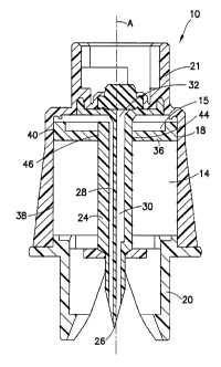
[0032] With reference to Figs. 1-7, a pressure equalizing device 10 according
to an
embodiment of the present invention is depicted. The pressure equalizing
device 10 includes
a container 12 defining an open chamber 14 and a sealed chamber 16. The open
chamber 14
and sealed chamber 16 are not in fluid communication with one another.
However, a thin
coating 18 or film may be applied to an inner wall of the container 12 as a
lubricant. The
film 18 may be transfened between the respective chambers 14, 16 provided that
no other
fluid transfer occurs. The open chamber 14 is, optionally, in fluid
conununication with
ambient air and at atmospheric pressure.
6
CA 02865502 2014-08-25
WO 2013/130971 PCT/US2013/028617
[0033] The device 10 further includes a connector 20 for attaching the device
10 to a
receptacle 22. The receptacle 22 may be any medical container formed from any
suitable
sterile material, including vials, cartridges, test tubes, sample collection
tubes, syringe
barrels, and the like. The device 10 is configured to permit pressure
equalization between the
sealed chamber 16 and the receptacle 22. The receptacle 22 may be a standard
medical vial
having a volume of 3 ml, 5 ml, 13 ml, 16.7 ml, or any other suitable standard
or customized
volume. The maximum volume of the container 12 preferably corresponds to the
volume of
the receptacle 22. However, the container 12 may range in volume from about 1
cm3 to about
1 litre, depending on the drug or substance being reconstituted. The
receptacle 22 may
contain a solid, liquid, or gaseous pharmaceutical, biological, or veterinary
substance and
may be sealed by means of a cap and/or an elastomeric stopper or membrane.
[0034] The pressure equalizing device 10 further includes a connector 21 for
attaching the
pressure equalizing device 10 to a fluid container 110, such as a syringe or
injector. The
connector 21 may be a luer-lock, bayonet, snap-fit mechanism, or other
connection capable of
establishing a removable connection between a cylindrical container and fluid
access port
[0035] The pressure equalizing device 10 further includes a fluid transfer
member 24, such as
a needle, needle cannula, lumen, channel, or spike, having a distal tip 26 and
defining a
venting channel 28. The venting channel 28 has a distal opening adjacent the
distal tip 26
for insertion into the receptacle 22. The venting channel 28 extends between
the receptacle
22 and the sealed chamber 16. The transfer member 24 further includes a fluid
access
channel 30 extending between an access port 32, at a proximal end of the fluid
transfer
member 24, and the distal tip 26.
[0036] The pressure equalizing device 10 further includes a pierceable
membrane 34 inserted
within or connected to the access port 32. The membrane 34 is configured to be
resealably
pierced by a needle or spike, thereby establishing fluid communication between
the needle or
spike and the access channel 30 through the membrane 34. In one non-limiting
embodiment
of the invention, the pressure equalizing device 10 also includes a second
membrane (not
shown) located at the distal end of the fluid transfer member 24 which is
arranged to be
pressed against the cap or sealing means of a receptacle 22.
[0037] As is shown in Fig. 7, the pressure equalizing device 10 has a
longitudinal axis A.
When the equalizing device 10 is attached to the receptacle 22, the
longitudinal axis A is
arranged in alignment and/or parallel with a longitudinal axis B of the
receptacle 22.
7
CA 02865502 2014-08-25
WO 2013/130971
PCT/US2013/028617
Furthermore, the fluid transfer member 24 and venting channel 28 are arranged
along the
longitudinal axis A of the pressure equalizing device 10.
[0038] As fluid is injected into the receptacle 22 or withdrawn therefrom, the
venting channel
28 of the pressure equalizing device 10 permits gas to flow from the interior
of the receptacle
22 into the sealed chamber 16 or from the sealed chamber 16 to the receptacle
22, thereby
equalizing the pressure in the interior of the receptacle 22 and in the sealed
chamber 16.
Fluid cannot exit the sealed chamber 16, which eliminates, or at least
reduces, the risk of any
substance inside the receptacle 22 being released into the atmosphere in gas
form or by way
of aerosolization during the insertion or withdrawal of the fluid transfer
member 24 from the
receptacle 22. Use of a pressure equalizing device 10 also reduces the risk
that pressure in
the receptacle 22 will increase. Increased pressure in the receptacle 22 may
cause the
receptacle 22 to leak or defon-n, further increasing the risk of contamination
of the
reconstituted fluid.
[0039] With continued reference to Figs. 1-7 and in one non-limiting
embodiment, the open
chamber 14 is delimited by a moveable wall 36 and rigid walls 38 of the
container 12. The
open chamber 14 is located between a lower surface of the moveable wall 36 and
the
receptacle 22. The moveable wall 36 may function as a piston which is moveable
within the
container 12 to equalize pressure within the receptacle 22 and sealed chamber
16. The
moveable wall 36 is freely moveable in that it will automatically transition
between a first
position, in which the wall 36 is adjacent to the proximal end of the
container 12, and a
second position in which the wall is adjacent to the distal end of the
container 12. The wall
36 is automatically moveable, in that it transitions from one position to
another based solely
on the withdrawal or injection of fluids from the receptacle 22. As fluid
enters the receptacle,
the moveable wall 36 moves downward through the container 12, thereby
increasing the
volume of the sealed chamber 16. As pressure in the receptacle 22 decreases,
the wall moves
in the proximal direction, thereby decreasing the volume of the sealed chamber
16.
[0040] In one non-limiting embodiment, the rigid walls 38 of the fluid
container 12 are made
of transparent or semi-transparent material so that the moveable wall 36 is
visible from the
outside of the pressure equalizing device 10 and can serve as a visual
indicator of how much
fluid has been added or removed from a receptacle 22.
[0041] The moveable wall 36 may be formed from a rigid or flexible material.
For example,
the moveable wall 36 can be constructed of one or more materials that are
fluid impermeable
(i.e., that does not permit the passage of a fluid), such as silicone, a
thermoplastic polyester
8
CA 02865502 2014-08-25
WO 2013/130971
PCT/US2013/028617
elastomer, (TPE), or rubber. The moveable wall 36 must create a seal between
the sealed
chamber 16 and the open chamber 14 for preventing vented gas from escaping
through the
open chamber 14 into ambient air. The moveable wall 36 may further include a
fluid
impermeable coating 40 and/or an outer annular seal 42, such as a ring-shaped
seal for
abutting the inner wall of the container 12.
[0042] In a further non-limiting embodiment, the moveable wall 36 is an
annular member
defining a central opening 46. The fluid transfer member 24 is inserted
through the central
opening 46. In this case, the moveable wall 36 may also include an inner
annular seal 44
disposed between the central opening 46 and the fluid transfer member 24
creating a seal
therebetween.
[0043] In a further non-limiting embodiment, the sealed chamber 16 is at least
partly filled
with sterilized air, which enters the chamber 16 through a fluid inlet (not
shown), such as a
valve, in communication with ambient air. A filter may be disposed within the
inlet to
sterilize the incoming air. The filter may be removable or integrated with the
inlet. The filter
may be any suitable commercially available filter, such as a particulate air
filter having a pore
size of 0.2 pm or smaller, a carbon filter, or a hydrophobic filter which
permits gas to pass
but prevents liquid, gas-borne particles, micro-organisms, and aerosols from
passing
therethrough. As described above, "sterilized air" refers to fluids that have
been subjected to
a sterilization method to remove viable micro-organisms using methods approved
by the
relevant regulatory authority. The open chamber 14 may also be provided with
fluid opening
defined by the container 12 to further ensure that the moveable wall 36 is
free to move within
the container 12.
[0044] As is depicted in Figs. 1 and 2, the pressure equalizing device 10 has
a substantially
cylindrical cross-section A. Alternatively, at least one part of a pressure
equalizing device 10
may have a substantially polygonal cross-section. Including a polygonal or
other non-
circular cross-section prevents the device 10 and/or attached receptacle 22
from rolling on a
flat or sloped surface.
[0045] Having described an embodiment of a pressure equalizing device 10, an
assembly 100
for drug reconstitution is now described. With reference to Fig. 7 and in one
non-limiting
embodiment, the assembly includes the pressure equalizing device 10,
receptacle 22, and
fluid container 110. The fluid container 110, such as a syringe, is used to
introduce a solvent
or drug component to the receptacle 22, through the access channel 30 of the
pressure
equalizing device 10. The fluid container 110 may further include a syringe
adapter or
9
CA 02865502 2014-08-25
WO 2013/130971 PCT/US2013/028617
injector 111 connected between thc syringe 110 and pressure equalizing device
10, as shown
in Fig. 7. The fluid container 110 should include a needle cannula, needleless
access port,
nozzle, or other access arrangement for establishing a fluid connection
between the fluid
container 110 and the access channel 30 of the device 10. The fluid container
110 may be at
least partially formed from a thermoplastic material, such as polyethylene or
polypropylene,
acrylonitrile butadiene styrene (ABS), polycarbonate, polyester, or any other
suitable
material, As shown in Fig. 7, the longitudinal axis A of the pressure
equalizing device 10 is
aligned with the longitudinal axis B of the receptacle 22 and with the
longitudinal axis C of
the fluid container 110, thereby forming a linear assembly.
[0046] In one non-limiting embodiment of the assembly and as is shown in Fig.
7, the
pressure equalizing device 10 may be integrally formed with at least one
component of the
receptacle 22. For example, the pressure equalizing device 10 may be
integrally formed with
a cap, neck, seal, or pierceable septum of the receptacle 22.
[0047] With reference now to Figs. 8 and 9 and in a further non-limiting
embodiment of the
pressure equalizing device 10, the container 12 includes a deformable bellows
52 disposed
within the container 12. The bellows 52 is disposed between a sealed chamber
16 and an
open chamber 14 in the same way that the moveable wall 36 maintained
separation between
the chambers 14, 16 in the previously described embodiments. The bellows 52 is
formed
from a flexible material such as rubber or plastic that expands or contracts
in response to a
change in volume of the sealed chamber 16. An inflatable balloon may also be
used in place
of the bellows 52.
[0048] With particular reference to Fig. 8, the bellows 52 are attached to a
distal portion of
the container 12. In this configuration, as fluid from the receptacle 22
enters the sealed
chamber 16 through the venting channel 28, the fluid flows around the bellows
52 causing the
bellows 52 to contract. As the bellows 52 contracts, the volume of the sealed
chamber 16
increases.
[0049] Alternatively, and with reference to Fig. 9, the bellows 52 are
attached to a proximal
end of the container 12. In this configuration, the bellows 52 expands as
fluid from the
receptacle 22 enters the sealed chamber 16 through the venting channel 28. The
volume of
the sealed chamber 16 expands, as the volume of the bellows 52 expands.
[0050] With reference to Figs. 10A and 10B and according to a further non-
limiting
embodiment of the invention, the pressure equalizing device 10 further
includes one or more
flexible joints 54 connected to or integrally formed with other structural
portions of the
CA 02865502 2015-12-16
WO 2013/130971 PCT/US2013/028617
pressure equalizing device 10. For example, the flexible joints 54 may be
included with the
rigid walls 38 of the container and/or the fluid transfer member 24, to permit
bending of the
container 12 and fluid transfer member 24. The flexible joints 54 may be
formed from any
flexible material, including plastic or rubber, which can be easily bent
without breaking, and
which maintains a bent orientation until straightened by a user. If the
flexible joints 54 are
integrally formed with the container 12 or fluid transfer member 24, then the
flexible joints
54 will be formed from the same material as the container 12 and/or member 24.
For
example, the flexible joints 54 may be formed from a thermoplastic material,
including
polyethylene or polypropylene, acrylonitrile butadiene styrene (ABS),
polycarbonate,
polyester, or any other suitable material. In use, a user can grasp the device
10 and/or
receptacle 22 and bend the flexible joints 54 to change the orientation of the
device 10
relative to the longitudinal axis (B) of the receptacle.
100511 It is noted that once the one or more flexible joints 54 are bent, the
longitudinal axis A
of the pressure equalizing device is no longer parallel with the longitudinal
axis B of the
receptacle 22. As shown in Fig. 10A, when the flexible joints 54 are in the
straight or
unbiased orientation, the longitudinal axis A of the device 10 is parallel
with the longitudinal
axis B of the receptacle 22. However, as shown in Fig. 10B, when the flexible
joints 54 are
in the bent orientation, axis A and axis B are not parallel. In one non-
limiting embodiment,
the flexible joint 54 is configured to bend up to about 90 degrees, thereby
permitting at least a
part of the pressure equalizing device 10 to be bent 90 degrees or more
relative to the
longitudinal axis B of the receptacle 22. By bending at least a portion of the
pressure
equalizing device 10 so that longitudinal axis A is not parallel to
longitudinal axis B of the
receptacle 22, the device 10 and receptacle 22 can be placed on a flat or
sloped surface.
Specifically, when in the bent orientation, it is less likely that the device
10 and receptacle 22
will roll along the surface, possibly damaging the device 10 and/or substances
contained
therein.
11