Note: Descriptions are shown in the official language in which they were submitted.
- 1 -
Method for Performing Immunoassays Under Weightlessness
The invention relates to a method for moving magnetic carriers in a controlled
manner in
a sample volume for performing immunoassays.
In biochemical analysis , the use of immunoassays is widespread This method
allows
selective quantitative or qualitative determination of single (monoplex) or
several
(multiplex) analytical parameters in a mostly complex biological matrix , such
as for
example blood, plasma, serum urine, saliva, tears, sweat, culture media, cell
extracts,
cel1suspensions etc which can contain a large number of substances
The general principle of immunoassays is that the desired analyte selectively
binds to a
specific protein-based capture antibody or to specific DNA, RNA or functional
subgroups
or segments based thereon (capture antibody = cAB) and is labeled by a
detection
antibody (detection antibody = dAB). The cA6 is mostly situated on a
stationary carrier
(solid phase)
In the standard literature, the nomenclature of the term -immunoassay" is
inconsistent.
Bebw both for classical immunoassays, and also ELISA (ELISA = enzyme linked
immunosorbent assay) with the use of enzymes, the term "immunoassay' is
understood
to mean that:
a) in classical immunoassays the dAB carries either a dye or a
fluorophor, which are
detected by spectrometry or fluorimetry
b) the ELISAs (ELISA = enzyme linked immunosorbent assay) are a further
immunoassay modification. These use an enzyme bound to dAB as the functional
label element. Since the start of the 1980s, the EL1SAs have replaced the RIAs
(Radio-Immuno Assays) which used a radioisotope as the label. The enzyme bound
to the analyte ,antibody complex via the dAB converts an added enzyme-specific
substrate bto a detectable substance which can be detected in the solution by
spectrometry or fluorimetry or by means of another physical effect, e.g.
chemiluminescence
In terrestrial use, the various solutions/substance are added sequentially The
free, non-
bound substances/reactants are removed by washing steps. The complexes formed
CA 2866087 2017-09-14
- 2 -
remain because of their binding to the stationary phase in the reaction
vessel, where they
can then be detected .
Mobib carriers are a special form of the solid phase. These are so-called
beads
(diameter nm - mm, but mostly a few pm) , onto the surface whereof the cAB
molecules
are bound. After the washing step, these carriers are separated from the
supernatant or
the residual solution by centrifugation or inthe case of magnetic carriers by
means of
strong magnets After completion of the overall reaction of the immunoassay ,
in terrestrial
applications the labeled carriers are read off either in a flow cytometer a
reading device
for multiwell plates or an array reader This can be effected as an integral
measurement
value or by image processing for each individual carrier or each array spot.
The steps described apply for immunoassays as a sandwich assay , as a
competitive
assay or also inthe form of an ELISA.
Immunoassays are also to be used in space flights under reduced gravity, or
even
weightlessness (pg) This means that substance transport or substance
separation are
slowed or entirely prevented because of the reduced or absent gravity During
sample
preparation on Earth, the reaction partners are moved in special mechanical
mixers (e.g.
orbital mixers or orbital shakers). Sedimentation for the observation occurs
by means of
gravity
Immunoassays with magnetic carriers are widespread for use on Earth below lug.
Previously, however, the magnetic carriers were primarily used for separation
during a
washing step The terrestrial procedures for immunoassays for cell
concentration or
separation are not suitable for use in space
The objective of the invention is to provide a process with which the
implementation of
immunoassays with magnetic carriers is possible under weightlessness or
reduced
gravity
According to the invention, for moving magnetic carriers in a controlled
manner in a
sample volume for performing immunoassays under weight essness. the magnetic
CA 2866087 2017-09-14
CA 02866087 2019-09-02
- 3 -
carriers within the sample volume are moved by means of permanent magnets
slidably
arranged relative to at least one spatial axis of the sample volume and for
mixing of the
magnetic carriers the permanent magnets arranged on one spatial axis are moved
in
phase.
The use of magnetic carriers e.g. as a solid phase enables active, controlled,
convective
mixing of the reaction partners by external magnetic fields which for example
operate
sequentially from different directions. In addition, the substance transport
is improved and
the reaction rate increased. A further advantage is that the procedure becomes
reproducible under weightlessness.
Finally, planar positioning of the magnetic particles for the purpose of
detection (e.g. in
the focal point of a microscope) is possible through a directed magnetic field
which can be
deliberately activated at a predetermined time.
Furthermore, it is possible to collect or hold the magnetic carriers in a
defined region, e.g.
during a change of fluid or a washing process, by means of a directed magnetic
field
which can be deliberately activated.
In addition, the magnetic carriers which are coated with a cAB can also be
used for
binding to specific cell types or membrane receptors, and in space experiments
with
reduced gravity these can be separated or concentrated or supplied by
mechanical
displacement for detection.
The absent or reduced gravity during the use of immunoassays in space is
compensated
by the appropriate use of magnetic carriers. The magnetic carriers are
influenced by
external magnetic fields activated in a controlled manner depending on the
process step.
For mixing of magnetic carriers in a sample volume, the permanent magnets are
advantageously arranged diametrically opposite relative to the sample volume.
For positioning of magnetic carriers on one plane within the sample volume,
permanent
magnets on a spatial axis that is perpendicular to the plane, where the
permanent
magnets lie, relative to the plane, diametrically opposite the magnetic
carriers to be
positioned, are advantageously in a first step moved in the direction of the
sample volume
and in a second step moved away from the sample volume.
CA 02866087 2019-09-02
- 4 -
The invention and further advantageous embodiments of the invention are
explained in
more detail below on the basis of diagrams:
Fig. 1 shows an example of a schematic arrangement for performing the method
according to the invention in a first application,
Fig. 2 shows an example of a schematic arrangement for performing the method
according to the invention in a second application, and
Fig. 3 shows an example of an implementation of a permanent magnet.
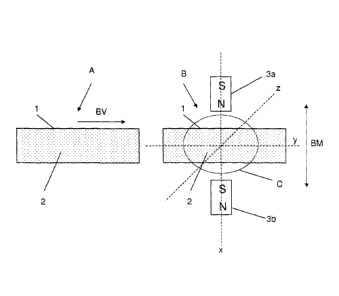
Fig. 1 shows an example of a schematic arrangement for mixing magnetic
carriers 2
within a sample volume 1. Outside the sample volume 1, permanent magnets 3a
and 3b
are arranged on one spatial axis x,y,z of the sample volume 1. For clearer
representation, only 2 permanent magnets 3 on the spatial axis x are shown in
Fig. 1. Of
course, further permanent magnets 3a and 3b can be arranged on the other
spatial axes
y and z.
The two permanent magnets 3a and 3b are arranged diametrically opposite
relative to the
sample volume 1, i.e. the sample volume 1 can be introduced into a region C
between the
two permanent magnets 3a and 3b. As is well-known, each permanent magnet 3a
and 3b
consists of a north pole N and a south pole S. It is advisable that the two
permanent
magnet 3a and 3b are arranged so that in each case the north and south pole
are facing.
Fig. 1 shows the arrangement with the sample volume 1 in a first position A,
in which the
sample volume 1 is situated outside the region B between the two permanent
magnets 3a
and 3b. The sample volume 1 can be shifted according to the arrow direction BV
into a
position B, so that the sample volume 1 is situated in the region C. Of
course, it is also
possible that the two permanent magnets 3a and 3b are appropriately shifted.
For mixing of the magnetic carriers 2 in the sample volume 1, the sample
volume 1 is
brought into position B. Next, the two permanent magnets 3a and 3b are moved
backwards and forwards in phase according to the arrow direction BM. The
magnetic
carriers 2 are now alternatingly oriented in the sample volume 1 in accordance
with the
adjacent magnetic field and correspondingly moved. Through the in-phase
backward and
forward movement of the two permanent magnets 3a and 3b, thorough mixing of
the
magnetic carriers 2 in the sample volume 1 is effected.
CA 02866087 2019-09-02
- 5 -
By appropriate arrangement and movement of other permanent magnets on the
spatial
axes y and z, the mixing can be improved.
Fig. 2 shows an example of a schematic arrangement for positioning magnetic
carriers 2
within a sample volume 1. The diagram shows a sample in position B
corresponding to
Fig. 1. For positioning of magnetic carriers 2 on the plane 5, the permanent
magnet 3a,
described below as the positioning permanent magnet, which is arranged on an
axis x
that is perpendicular to the positioning plane 5, is used. This permanent
magnet 3a which
relative to the positioning plane lies diametrically opposite the magnetic
carriers 2 to be
positioned can be shifted in accordance with the arrow directions BM1, BM2.
Another permanent magnet 3b relative to the sample volume 1 arranged
diametrically to
the positioning permanent magnet 3a on the spatial axis x is shifted into a
parking
position P and protected by means of a screening device 4, so that magnetic
fields of the
permanent magnet 3b can have no influence on the magnetic carriers 2 in the
sample
volume 1.
For positioning the magnetic carriers 2 in the sample volume 1, the
positioning permanent
magnet 3a is shifted in the direction BM1 of the plane 5. Thereby, the
magnetic carriers 2
are oriented and moved in the direction of the plane 5. Next, the positioning
permanent
magnet 3a is shifted in the direction BM2 and shifted into a corresponding
parking
position P (not shown).
During use in space, the magnetic carriers remain in this position until the
end of the
detection, since because of the reduced gravity no sedimentation or thermal
convection
occurs in the sample volume.
Fig. 3 shows by way of example the implementation of a permanent magnet. The
permanent magnets are advantageously implemented as a matrix. The permanent
magnet 3a comprises several permanent magnets 30a, which are advantageously
arranged as a matrix wherein the permanent magnets 30a are arranged
alternately.