Note: Descriptions are shown in the official language in which they were submitted.
CA 02866577 2014-09-05
WO 2013/134554
PCT/US2013/029703
PCT Application
Enhanced Biometry Using Optical Coherence Tomography
Michael Hee, Jay Wei, Ben Jong, Tony Ko
Related Applications
[0001] This application claims priority to U.S. Provisional Application No.
61/608,047,
filed on March 7, 2012, and to U.S. Nonprovisional Application No. 13/789,283,
filed on
March 7, 2013, which are herein incorporated by reference in their entirety.
Background
1. Field of the Invention
[0002] Embodiments of the present invention relate to a device for optical
coherence
tomography for determining geometric structures and optical biometry of the
eye. In
particular, embodiments of the present invention relate to a device for
optical coherence
tomography for determining the power of an intraocular lens implant and the
condition of the
retina.
2. Description of Related Art
[0003] Modern intraocular lens 000 calculation formulas rely on the
measurement of
several geometric parameters of the eye in order to calculate the power of an
implanted
intraocular lens after cataract surgery. Third-generation formulas such as the
SRK/T
(Retzlaff JA, Sanders DR, Kraff MC, "Development of the SRK/T intraocular lens
implant
power calculation formula" J Cataract Refract Surg 1990; 16:333-340) ,
Holladay 1
(Holladay JT, et al., "A 3-part system for refining intraocular lens power
calculations" J
Cataract Refract Surg 1988; 14:17-24), and HofferQ (Hoffer KJ., "The Hoffer Q
formula: A
comparison of theoretic and regression formulas" J Cataract Refract Surg 1993;
19:700-712.)
1
CA 02866577 2014-09-05
WO 2013/134554
PCT/US2013/029703
require measurement of axial eye length and corneal curvature. Fourth-
generation formulas
such as Holladay 2 (available from Holladay et al.,
http://www.hicsoap.com/topic/12-
hicsoap-professional-edition.aspx) and Haigis (Haigis W, et al., "Comparison
of ultrasound
biometry and partial coherence interferometry for intraocular lens calculation
according to
Haigis" Graefe's Arch Clin Exp Ophthalmol 2000; 238; 765-773) also require
additional
parameters, including anterior chamber depth and lens thickness, which allow
for more
accurate calculations. These parameters are important for estimating the
effective lens
position (ELP) of the IOL in the eye.
[0004] An ultrasound A-scan may be used to measure axial eye length.
However, the
results from ultrasonic measurements may be less accurate and less
reproducible than optical
methods. First, the ultrasonic wavelength is typically longer than the optical
wavelength
making the ultrasonic measurements less precise. Second, if a contact
ultrasonic probe is
used, pressure applied to the cornea may distort the axial length measurement.
Third, an
immersion ultrasonic probe can be uncomfortable for the patient. Finally, it
is difficult to
accurately place the ultrasound probe on the desired measurement axis of the
eye. However,
the ultrasonic measurement can often be performed even when there is a dense
cataract,
which renders measurement using optical methods difficult.
[0005] The health of the eye is an important consideration prior to
cataract surgery.
Current optical biometers only obtain measurements on a single axis of the eye
and are
therefore unable to create an image of the cornea or retina.
[0006] Conventionally, measurements of corneal curvature and axial
length are obtained
with two different instruments or two different measurement beams. For
example, if
ultrasound is used to measure the axial eye length, a separate optical
keratometer or a
topographer are used to measure the corneal curvature. Some devices use
optical methods to
measure the axial length and corneal curvature. In these methods, partial
coherence
2
CA 02866577 2014-09-05
WO 2013/134554
PCT/US2013/029703
interferometery is used to measure the axial length and a separate optical
keratometer is used
to measure the corneal curvature. In other methods, the principle of partial
coherence
interferometry is used to measure the axial length, but a Scheimpflug image
(Scheimplfug T.,
"Der Photoperspektograph und Seine Anwendung. Photogr" Korresp 1906; 43:516)
is used
to derive the anterior chamber depth and the lens thickness needed for the IOL
calculation.
The Scheimpflug principle describes how the image or camera plane, lens plane,
and object
planes of an optical system can be oriented such that the object plane is
completely in focus
at any depth.
[0007] The traditional third and fourth generation IOL formulas assume a
fixed ratio
between the curvature of the anterior and posterior surfaces of the cornea.
Only a
measurement of corneal anterior curvature is therefore required to compute
corneal refractive
power and IOL implant power after cataract surgery. However, in unusual eyes
or eyes that
have undergone refractive surgery, the relationship between the anterior and
posterior corneal
surfaces is likely to be altered and the assumptions of the traditional IOL
calculation formulas
become invalid.
[0008] Therefore, there is a need for methods and apparatus to perform
biometry
measurements.
Summary
[0009] In accordance with some aspects of the invention, an imaging
method is disclosed.
An imaging method according to some embodiments can include obtaining a
plurality of
measurements of an eye for at least one location by scanning optical radiation
across the eye;
determining a preferred measurement axis from the plurality of measurements;
and
processing the plurality of measurements to obtain information of the eye.
[0010] In some embodiments, an apparatus includes a scanner for scanning
optical
radiations across an eye to acquire measurements from at least one surface and
at least one
3
CA 02866577 2014-09-05
WO 2013/134554
PCT/US2013/029703
internal structure of the eye simultaneously; a lens for focusing the optical
radiations on the
surface of the eye; a negative power lens for focusing the optical radiation
on an internal
structure of the eye; and a processor to generate at least one image from the
plurality of
measurements.
[0011] These and other embodiments are further discussed below with respect
to the
following figures.
Brief Description of the Drawings
[0012] FIG. 1 illustrates a schematic of an optical biometer based on
partial coherence
interferometry.
[0013] FIG. 2A illustrates an optical coherence tomography system used for
simultaneously imaging the cornea and the retina.
[0014] FIG. 2B illustrates images of the cornea and the retina
simultaneously acquired
using the system shown in FIG. 2A.
[0015] FIG. 3A shows an exemplary volume scan pattern in accordance with
some
embodiments.
[0016] FIG. 3B shows the same scan pattern illustrated in FIG. 3A
superimposed onto an
eye with good fixation.
[0017] FIG. 3C shows the same scan pattern illustrated in FIG. 3A
superimposed onto an
eye with poor fixation.
[0018] FIG. 4A shows example measurements of a normal eye.
[0019] FIG. 4B shows example measurements of an eye with a cataract.
[0020] FIG. 5 illustrates an exemplary optical layout to obtain a
simultaneous reflection
from the cornea and the retina according to some embodiments.
[0021] FIGs. 6A, 6B, and 6C show exemplary images of the cornea, the
retina, and the
cross-sectional measurements using the optical arrangement in FIG. 5,
respectively.
4
CA 02866577 2014-09-05
WO 2013/134554
PCT/US2013/029703
[0022] FIG. 7 shows an exemplary image of the cornea according to some
embodiments.
[0023] FIG. 8 shows a flowchart of the invention according to some
embodiments.
[0024] FIG. 9 shows a pictorial representation of an eye with different
measurement axes.
Detailed Description
[0025] Various embodiments of the present invention are described below
with reference
to the accompanying drawings. It is understood that figures have been
simplified for the
purposes of explanation herein while leaving out elements which are
conventional in the art.
[0026] Optical methods of axial eye measurement described below can
provide a high
precision measurement because the wavelength of light is smaller than the
ultrasonic
wavelength. Measurements using optical methods can also be obtained without
contact with
the eye. In addition, the user may be able to manually align the optical
measurement beam to
the desired optical axis of the eye by monitoring the specular reflection of
light from the
cornea.
[0027] In some embodiments, the optical biometry can be improved by
utilizing a
plurality of measurements acquired at a plurality of transverse locations
across the eye. In
some embodiments, an apparatus that can couple an optical biometer to a beam
scanning
mechanism and a method utilizing the plurality of measurements to obtain the
desired
geometric properties of the eye with better accuracy and improved ease-of-use,
especially
under the conditions of dense cataract or poor user alignment on a preferred
measurement
axis of the eye, can be provided.
[0028] In some embodiments, a method that uses the optical reflections
from the cornea
obtained from the plurality of measurements to locate the desired optical axis
of the eye, such
as, the cornea vertex normal can be performed. With this method, a measurement
of axial
length coinciding with the cornea vertex normal can be selected from the
plurality of
measurements, even if the instrument is not perfectly centered on the cornea
vertex normal.
5
CA 02866577 2014-09-05
WO 2013/134554
PCT/US2013/029703
[0029] In some embodiments, an apparatus for forming a simultaneous
optical image of
the cornea and retina can include a lens to focus optical radiation on the
cornea, and a
negative lens to simultaneously focus the optical radiation on the retina. In
some
embodiments, the apparatus allows a measurement of axial eye length to be
performed from
the simultaneous optical reflections from both the corneal and retinal
surfaces. The apparatus
can also provide simultaneous optical images of the retina and cornea capable
for evaluating
the health of the eye prior to considering any surgical intervention, such as
a cataract surgery.
[0030] In some embodiments, a method for using the plurality of
measurements to
improve measurement accuracy through dense cataracts or cataracts with focal
opacity can be
performed. In some embodiments, an array of measurements may be obtained at
different
transverse locations so that at least some measurements would avoid the focal
opacity. The
locations of the measurements may be spaced closely enough to avoid the
influence by retinal
curvature and to permit averaging of the optical signal from the retina to
enhance penetration
through a dense cataract. The position of the apex of the cornea can be
located from the
plurality of measurements by means of peak detection or curve fitting.
[0031] In some embodiments, a method for using the plurality of
measurements to define
the curvature of the anterior cornea, the curvature of the posterior cornea,
the anterior
chamber depth, and the lens thickness, which are additional parameters that
are important for
intraocular lens power calculation, can be performed. These measurements can
be obtained
with a single measurement beam in a single device.
[0032] Methods of using low-coherence or partial coherence
interferometry to measure
axial eye length are disclosed. There are two commercial instruments that use
the technique
of partial coherence interferometry to measure the geometric properties of the
eye. The
IOLMaster (Carl Zeiss Meditec, USA) measures the interference signal between
the corneal
reflection and the retinal reflection to provide a measurement of axial eye
length. This
6
CA 02866577 2014-09-05
WO 2013/134554
PCT/US2013/029703
measurement is relatively insensitive to the longitudinal distance between the
cornea and the
instrument because the detected interference signal only depends on the
relative distance
between the cornea and retina. However, the user must manually adjust the
horizontal and
vertical position of the instrument itself in two transverse dimensions along
the desired
measurement axis of the eye for alignment. Accurate manual alignment can be
difficult to
achieve in eyes with poor fixation or poor cooperation from the patient. In
clinical practice,
this method requires the anterior chamber depth and lens thickness to be
obtained separately
from a video image of an off-axis slit-beam incident on the cornea, iris and
lens; this separate
method provides measurements that are less accurate than measurements that
could otherwise
be obtained using an interfero metric method.
[0033] According to some embodiments of the present invention,
measurements for both
the anterior chamber depth and lens thickness using interferometric method can
be utilized. In
addition, corneal curvature, axial length, and lens thickness, can be measured
with a single
measurement beam in a single instrument.
[0034] The Lenstar (Haag Streit, Switzerland) is another instrument that
employs time-
domain low coherence interferometry to measure the geometric properties of the
eye. The
Lenstar measures the interference signal formed between the reflective
boundaries within the
eye and a reference optical path of varying length. The use of a reference
optical path allows
a measurement of the corneal thickness, the anterior chamber depth, the lens
thickness, and
the axial length to be obtained simultaneously. However, the user manually
aligns the
instrument in 3 dimensions with respect to the location of the cornea to
obtain an absolute
reference of the optical path distance, which is likely to be less accurate in
eyes with poor
fixation or poor cooperation from the patient.
[0035] According to some embodiments of the present invention, a
plurality of
measurements at different optical axes is obtained, allowing automatic
selection or
7
CA 02866577 2014-09-05
WO 2013/134554
PCT/US2013/029703
reconstruction of the desired measurement post processing with less
measurement error due
to user input or manual alignment. In addition, the plurality of measurements
obtained by
some embodiments may be constructed into an image of the cornea and retina. An
optical
apparatus is disclosed herein that allows simultaneous imaging of the cornea
and retina.
[0036] A common disadvantage of previous optical methods used for measuring
the axial
eye length is that the optical beam usually employed cannot penetrate a very
dense cataract,
which causes significant light scattering. A method was proposed to solve this
problem by
increasing the measurement time to enable measurements through a dense
cataract. In some
instances, the area of the strongest light scattering may be localized to a
particular portion of
the lens. This condition may be more likely to occur with an anterior polar,
posterior polar,
posterior subcapsular, or focal anterior cortical cataract. In these cases, an
optical
measurement of axial eye length could possibly be obtained if the instrument
were aligned on
a preferred measurement axis of the eye which avoided the dense lens opacity.
Manually
locating the preferred measurement axis in this situation adds difficulty for
the operator.
[0037] In some embodiments of the present invention, a plurality of
measurements on
multiple measurement axes is acquired so that at least one light beam could
avoid the dense
lens opacity and produce useful measurements.
[0038] Additionally, some embodiments of the present invention are able
to measure both
the anterior and posterior corneal curvatures simultaneously with a single
measurement beam,
allowing a more accurate calculation of the net corneal power after refractive
surgery. As
discussed below, optical measurements can be obtained using low-coherence
interferometry,
partial coherence interferometry, or optical coherence tomography.
[0039] FIG. 1 shows the optical layout of a dual beam interferometer 100
with partially
coherent light. A measurement of axial eye length is performed along a single
measurement
axis of the eye 109 at a time. In some embodiments, a scanning mechanism (not
shown) can
8
CA 02866577 2014-09-05
WO 2013/134554
PCT/US2013/029703
be included to obtain a plurality of measurements over an area of eye 109. As
shown in FIG.
1, a light source 101 with a short coherence length provides light to a beam
splitter 106. The
light is split into a path incident on mirror 103 and a path incident on
mirror 104. These two
light paths are recombined at beamsplitter 106 and incident onto the eye 109
where it is
reflected from both the cornea and retina. After reflection from beamsplitter
107, an
interference signal appears at detector 108 when the axial eye length d
matches the difference
in optical path length Nd between the location of mirror 104 and the
equivalent distance 105
as that to mirror 103, shown as a dashed line.
[0040] FIG. 2A shows the optical layout of an extended range OCT that
incorporates two
reference arms and a phase generator in one of the references arms to create a
full range
Fourier domain interferometer that is capable of measuring the eye length. As
shown in FIG.
2A, OCT apparatus 200 includes a light source 201 coupled to provide light to
a
splitter/coupler 203. Splitter/coupler 203 receives light from optical source
201 and sends the
energy into both sample arm 213 and reference arm 212. Sample arm 213 may
include
various collimating lenses 209 and focusing lenses 210. Additionally, sample
arm 213
includes a beam scanning mechanism 216 to direct the beam to perform two- or
three-
dimension transverse beam scanning and imaging of a sample 211. For achieving
simultaneous imaging, reference arm 212 includes an additional
splitter/coupler 204 that
separates the beam of light received from splitter/coupler 203 into two or
more reference arm
paths, such as reference path 214 and reference path 215. Reference path 214
includes
collimating lenses 205 and mirror 207. Reference path 215 includes collimating
lenses 206
and mirror 208. Collimator lenses 205 and 206 in reference paths 214 and 215,
respectively,
collimate the beam from an optical fiber coupled to splitter/coupler 204 and
focuses the
beams back into the optical fiber after it is reflected from reference mirrors
207 and 208,
respectively.
9
CA 02866577 2014-09-05
WO 2013/134554
PCT/US2013/029703
[0041] In some embodiments, reference mirror 207 is adjusted to
correspond to the
anterior segment of the eye while reference mirror 208 is adjusted to
correspond to the
posterior segment of the eye. The beams returning from the sample arm 213 and
reference
arm 212 are combined in splitter/coupler 203 and transmitted to detection
system 202. The
detected signal can then be sent to a processor 218. Phase generator 217
allows the processor
218 to distinguish the signals returning from the anterior and posterior eye.
In some
embodiment of the present invention, a transverse beam scanning mechanism 216
is included
in this configuration to allow a plurality of measurements to be obtained
along varying
optical axes of the eye. Scanning mechanisms that can be used for scanner 216
or in other
measurement techniques can include, for example, mirror that is tilted using a
galvanometer
or microelectromechanical (MEMS) device, an acousto-optic modulator, a
variable
diffraction grating, or other mechanical translation of the beam incident on
eye 109.
[0042] Processor 218 can be, for example, a computer system including
one or more
processors, internal memory, data storage facilities, and user interfaces.
Processor 218 is
capable of storing the received image, displaying the image, and analyzing the
image
according to instructions as described further below.
[0043] FIG. 2B shows an example imaging technique using apparatus 200 as
illustrated
in FIG. 2A. In FIG. 2B, imaging regions 221 and 222 are of interest in eye
211. The optical
path in two reference mirrors can be adjusted such that one reference mirror
images the front
part of the anterior chamber while the second reference mirror images the
retina in the
posterior segment of the eye 211. The anterior and posterior eye images will
be a
superimposed image 223, but can be separated to the anterior chamber image 225
and
posterior segment image 224, by the processing unit using the phase
information provided by
the phase generator 217.
CA 02866577 2014-09-05
WO 2013/134554
PCT/US2013/029703
[0044] FIGs. 3A, 3B, and 3C disclose a scan pattern for obtaining the
plurality of axial
eye measurements according to some embodiments of the present invention. In
FIG. 3A, the
measurement beams are scanned in a 2 dimensional array 300 in the x-y plane
with the
measurement beam going into the page in the z-direction indicated by dots 310.
Each dot
310 represents an A-scan, and the combination of A-scans produces a 3
dimensional volume
of geometric measurements covered by the scan array 300. The scan beams 310
can be
arranged in alternate configurations, such as an unequally spaced mesh. In
some
embodiments, the scanning can follow the scan direction 320 to obtain the 3D
data volume.
The array of measurements 300 is advantageous over other biometry methods
because
multiple measurements at different locations can be obtained within a single
scan.
[0045] One advantage of the plurality of measurements 300 over the prior
art is that as
long as the entire array is positioned approximately over the desired
measurement axis of the
eye, there is increased probability that at least one measurement beam will be
coincident or
approximately coincident with the preferred measurement axis, which can be the
cornea
vertex normal or the corneal apex, or center of the pupil. As is customary in
the art, axial eye
length measurement is usually acquired along the eye's direction of fixation
or the direction
of sight. In other methods, the optical biometer might be further aligned by
the operator until
a specular reflection from the cornea is located, which defines the cornea
vertex normal. In
situations with uncooperative patients, or patients with dense cataract, or
corneal or retinal
disease, it may be difficult for the operator to locate the corneal vertex
normal accurately due
to excessive eye motion or poor fixation. An inexperienced operator may also
have more
difficulty performing proper alignment. The rapid acquisition of the array of
measurements
300 according to some embodiments of the present invention increases the
probability that at
least one of the measurements is exactly or approximately coincident with the
preferred
measurement axis, customarily the cornea vertex normal.
11
CA 02866577 2014-09-05
WO 2013/134554
PCT/US2013/029703
[0046] There are several methods whereby the preferred measurement axis
may be
determined from a plurality of corneal measurements. In some embodiments, the
preferred
measurement axis may be directly selected from the plurality of measurements
using criteria
such as location information with respect to the pupil. The axial location of
the cornea can
then be selected to correspond to the corneal reflection on the preferred
measurement axis.
[0047] FIG. 9 shows a variety of possible measurement axes such as the
pupillary axis
(optical axis) 905, the line-of-sight 915, the visual axis 920, or the corneal
vertex normal 930.
The pupillary axis 905 is defined by a ray passing perpendicularly through the
center of the
pupil 910. The line-of-sight is defined by a ray which passes through the
center of the pupil
910 and reaches the fovea 940. The visual axis 920 is a straight line passing
through the
eye's optical nodal point 950 and intersecting the fovea 940. The corneal
vertex normal 930
is defined by a ray which intersects the fovea 940 and is perpendicular to the
curve of the
anterior cornea 960.
[0048] A preferred measurement axis or axial distance to the cornea can
be determined
by a function of the corneal reflections using all or some of the plurality of
measurements.
For example, the location of the corneal reflection along the preferred
measurement axis can
be located by user review of the individual measurements, or be automatically
or semi-
automatically determined by a processing unit. In some embodiments, the
processing unit
may evaluate the plurality of measurements to identify the measurement with
the strongest
corneal reflection, typically occurring at the corneal vertex normal 930, as
indicative of the
preferred measurement axis. Optical measurements acquired along a measurement
axis close
to the corneal vertex normal 930 often produce a stronger reflection than
measurements from
other locations due the more normal incidence of the measurement beam onto the
curved
corneal surface. In some embodiments, the corneal apex 900, the highest point
of the cornea
having the largest mean curvature, may be identified by applying a curve
fitting to a subset or
12
CA 02866577 2014-09-05
WO 2013/134554
PCT/US2013/029703
to all of the measurements, in 2 or 3 dimensions. In other embodiments, an
average, or
median, or other statistical function of the corneal measurements may be used
to identify this
location as the preferred measurement axis. Other methods of identifying the
location of the
corneal reflection will be apparent to those skilled in the art using the
plurality of the
measurement disclosed herein. It is also apparent that these methods may apply
equivalently
to other possible preferred measurement axes, such as an optical axis defined
by the line-of-
sight, the pupillary axis, or the visual axis.
[0049] FIG. 3B illustrates application of data array 300 onto an eye
211. Eye 211
includes cornea 340 with pupil 348. As shown in Figure 3B, the A-scans of data
array 300
are within pupil 348. The preferred measurement axis may be selected from the
plurality of
measurement axes, such as the pupillary axis 905, the line-of-sight 915, the
visual axis 920,
or the cornea vertex normal 930. Measurement axis 342 in FIG. 3B corresponds
to the line-
of-sight axis 905. In FIG. 3C, the A-scans of data array 300 only partially
overlap the pupil
due to either eye motion, poor patient fixation, or improper instrument
alignment. However,
a measurement 346 along the line-of-sight axis 905 may still be obtained from
the data array
300.
[0050] The relationship between the transverse dimensions of the array
of measurements
300 and the curvature of cornea 340 further influences the identification of
the preferred
measurement axis. The average radius of curvature of cornea 340 is
approximately r = 7.6 mm and therefore the axial position z of a given corneal
reflection can
vary by approximately Az z h2/(2r) from the corneal apex to a peripheral
location on cornea
340, where h denotes the radial distance from the corneal apex to the
peripheral location.
[0051] In some embodiments, an average, or median, or other evaluation
of the corneal
measurements may be used to identify the optimal corneal location. In normal
eyes, the
intraocular lens 000 power is approximately related to the axial length by a
factor of 2.5
13
CA 02866577 2014-09-05
WO 2013/134554
PCT/US2013/029703
(2.5 x axial length in mm); that is, a 30 micron variability in axial length
is equivalent to
about a 0.08 diopter (D) variation in IOL power. Currently, IOLs are usually
available in 0.5
increments, although some are available in 0.25 D increments. Therefore, a
less than 30
micron variability in axial length measurement is not clinically significant
in the choice of
IOL implant power after cataract surgery. For example, as shown in FIG. 3B, if
the array of
measurements 300 spans a linear distance of 1 mm diameter centered on the line-
of-sight 342
of an average human cornea 340, the location of the most peripheral
measurement 344 along
the x and y axis will be approximately Az z (0.5 mm)2/(2. 7.6 mm) =16 microns
closer to
the retina in the z-direction than the location from the central measurement
taken at the line-
of-sight 342. Since the variation in the entire 1 mm x lmm array of locations
in array 300
has negligible effect on the clinical use of the calculated IOL power, the
array of
measurements 300 of the corneal surface can be averaged to estimate the axial
length.
However, if for example, the array of measurements spans a 2 mm diameter on
the cornea,
the variation in the location of the corneal surface will be increased to
approximately 65
microns. Obtaining the axial length using the average corneal measurements may
have more
influence on an IOL calculation. In this case, a curve-fitting or peak
detection process can be
used to identify the corneal measurement closest to the vertex normal, which
would also be
the measurement that produces the longest axial length. For the reasons stated
above,
differences in patient motion and operator training render inconsistent and
inaccurate
measurement location. In accordance with some embodiments of the present
invention, the
additional measurement data obtained using the array of measurement 300
provide flexibility
to select and/or process multiple measurements to estimate the best corneal
measurement.
[0052]
The plurality of A-scan measurements also improves the accuracy in identifying
the retinal reflection. The short optical wavelength used in optical method
leads to
measurement with higher axial resolution; optical biometry method commonly
known in the
14
CA 02866577 2014-09-05
WO 2013/134554
PCT/US2013/029703
art can distinguish multiple retinal reflections, including reflections from
the inner surface of
the retina and the retinal pigment epithelium (RPE). Any of these measurements
may be used
to locate the position of the retina in order to determine the axial eye
length.
[0053] The preferred measurement axis often intersects the center of the
fovea as this is
the retinal location responsible for the greatest visual acuity. In patients
with macular
disease, such as geographic atrophy, myopic degeneration and staphyloma,
macular hole, the
patient may have difficulty fixating on an alignment light which is generally
coincident with
the measurement beam. FIG. 3C shows an example of the array of measurements
300 used in
a patient with poor fixation. Here, a plurality of measurements 300 is
acquired at different
transverse locations across the retina and the array of measurements 300 is
used to increase
the probability of obtaining a measurement through the preferred measurement
axis. In the
example illustrated in FIG. 3C, the measurement closest to or impinging on the
fovea may be
selected for further measurement analysis and calculations. In FIG. 3C, beam
346 is the
beam location most closely corresponding to the preferred measurement axis.
[0054] FIG. 4A show an exemplary cross-section of eye 211 with a plurality
of optical
beams 402 going through a normal eye and impinge onto the fovea 410. The
plurality of
measurements provide data for further analysis and processing for both the
anterior and the
posterior segments, as illustrated in data plots 404 and 406 illustrated in
FIG. 4A. Plot 404
illustrates the array data 300 as a function of distance to cornea reflection
for both anterior
cornea reflection and posterior cornea reflection from cornea 340. Plot 406
illustrates the
array data 300 as a function of distance to retina reflection for the inner
retinal reflection and
RPE reflection of retina 410. Since the preferred measurement axis often
intersects the center
of the fovea, in patients with fixation difficulty, the image of the fovea can
be used in some
embodiments of the present invention to determine the preferred measurement
axis 408.
CA 02866577 2014-09-05
WO 2013/134554
PCT/US2013/029703
[0055] Some methods according to embodiments of the present invention
may also have
advantages over previously proposed solutions in identifying the retinal
reflection in the
presence of a dense cataract or a cataract with a dense focal opacity. A dense
focal lens
opacity, such as opacity 354 in FIG. 4B, may be especially apparent in some
cases of an
anterior polar, posterior polar, posterior subcapsular, or anterior cortical
cataract. In the
presence of a dense focal opacity, automatically obtaining a plurality of
measurements at
varying transverse locations may allow one or several measurements to be
performed through
a region of the cataract which is less dense. FIG. 4B illustrates an example
of such
processing. In some embodiments of the present invention, a plurality of
measurements can
be acquired using the scan array 300 to avoid a focal opacity 354 which
improves upon the
prior art where the user would have to manually re-align the optical biometer
to find a less
dense region of the cataract. Using the plurality of measurements, the user
can then select the
strongest retinal reflection or to perform further processing in order to
compute the location
of the retina. Alternatively, a function of the plurality of retinal
measurements such as
averaging or curve fitting may be employed to determine the retinal location.
[0056] In the presence of a uniformly dense cataract, the optical
reflections from the
retina will be weak, and the plurality of measurements at varying transverse
locations allows
the retinal reflection to be more accurately determined from a function based
on the plurality
of measurements, rather than just a measurement taken from a single retinal
location. For
example, the strongest retinal reflection from the plurality of retinal
reflections may be
selected. Alternatively, the plurality of retinal reflections may be averaged.
In this manner,
the visibility of the average reflection can be enhanced in the presence of
noise, which is
reduced by the averaging.
[0057] The ability to perform averaging on measurements of the retina
might be affected
by the curvature of the retina 410 and the transverse extent of the
measurement volume. The
16
CA 02866577 2014-09-05
WO 2013/134554
PCT/US2013/029703
radius of curvature of the retina 410 in normal eyes is approximately 13.4 mm
and is larger
than the radius of curvature of the cornea 340. A maximum transverse
displacement of the
A-scan of 0.5 mm on the retina allows the plurality of measurements to be
acquired in a lmm
x lmm volume and only an estimated Az z h2/(2r) = 9 micron variability in the
axial position
of the retinal reflection. Therefore, if the scanning volume is relatively
small (eg. lmm x
lmm), the measurements of the retinal reflections can be averaged to obtain
measurements in
the presence of a dense cataract opacity 354 without significantly affecting
the measurement
precision. For significantly larger measurement volumes, the radius of
curvature of the retina
410 might be more significant. In this case, alternative processing methods,
such as curve
fitting, can be used to derive the optimal retinal location from the plurality
of retinal
locations, as illustrated in the plots in FIG. 4B. Applying curve fitting to
multiple retinal
measurements will have an effect similar to averaging because measurement
noise which
strongly affects a single measurement will have a substantially weaker effect
on the position
of a curve determined by multiple measurements.
[0058] The method of automatically obtaining a plurality of biometer
measurements at
separate transverse locations also improves on the prior art by improving on
the ability to
evaluate the health of the eye, which is important in the consideration of
whether or not to
proceed with cataract surgery. In some embodiments, the pattern of transverse
measurement
locations can be a regularly spaced two-dimensional array 300. The array of
measurements
comprising the depth of reflections from structures on the surface or within
the eye may be
combined and displayed as a two-dimensional cross-sectional image, or a three-
dimensional
volume of eye structures. For example, the presence of retinal abnormalities,
such as
epiretinal membrane, macular edema, or other pathology, may be determined from
a cross-
sectional image and can provide valuable information in evaluating the visual
potential of an
eye about to undergo cataract surgery. In the presence of normal retinal
anatomy, the
17
CA 02866577 2014-09-05
WO 2013/134554
PCT/US2013/029703
location of the fovea can be accurately identified based on its characteristic
morphological
features, such as the foveal depression/pit which is related to the lack of
retinal nerve fiber
layer, inner plexiform layer and inner nuclear layer in the region. In a
similar manner, cross-
sectional or volume images of the cornea, anterior chamber, or lens may also
be obtained
with a single optical biometer.
[0059] It will be evident to practitioners skilled in the art that any
method of beam
scanning or translation may be used to obtain the plurality of measurements at
different
transverse locations. Methods of beam scanning includes, but are not limited
to,
mechanically tilting a mirror using a galvanometer or microelectromechanical
(MEMS)
device, employing an acousto-optic modulator or variable diffraction grating,
or mechanically
translating the beam light source or an optical element in the beam path.
Alternatively,
multiple measurement beams may be employed either simultaneously or in
succession to
achieve the same purpose of obtaining measurements at varying transverse
locations.
[0060] FIG. 5 illustrates an exemplary optical layout according to some
embodiments to
simultaneously image the cornea and the retina with a wide field-of-view. The
optical beam
exits from a focusing lens 500 onto a bifocal lens 501. The bifocal lens is
composed of a
central negative lens element 503 which collimates the focused beam (solid
line) before it is
incident on the corneal surface 505. The beam is then focused by the eye 504
onto the retina
507. The peripheral zone 502 of the bifocal lens 501 is a flat optical
surface. This surface
does not change the beam (dotted line) emerging from the focusing lens, and
the beam
remains focused onto the cornea. In this optical arrangement, the beam is
simultaneously
focused on the central retina and the paracentral cornea. Therefore,
simultaneous
measurements of the corneal location and the retina location may be performed
as shown in
FIG. 5. The optical layout in FIG. 5 using the bifocal lens 501 can be
incorporated into the
imaging apparatus shown in FIG. 2A to obtain simultaneous measurements of the
cornea and
18
CA 02866577 2014-09-05
WO 2013/134554
PCT/US2013/029703
the retina. In some embodiments, the bifocal lens 510 can be placed between
the focusing
lens 210 and the object 211 in FIG. 2A, or any other location obvious to a
person of
reasonable skills in the art.
[0061] In FIG. 5, if the bifocal lens 501 is not present, then the beam
would remain
focused on the cornea at every measurement location and only corneal
measurements would
be obtained. In this case, the beam would be divergent at the retina 407, and
therefore only a
very weak, undetectable retinal reflection would be present, even in the
absence of cataract
506. Alternatively, if the bifocal lens 501 consists of a single negative lens
element 503,
then the beam can be focused on the retina 507, but remain collimated at the
cornea 505 at
every measurement location. A collimated beam can provide a sufficient corneal
reflection in
the central cornea due to the normal incidence of the measurement light, but
the reflections
from the paracentral cornea can be weak because the angle of the corneal
surface would tend
to reflect the measurement light away from the instrument. Therefore, the
bifocal lens design
provides advantages in the ability to obtain a simultaneous wide field-of-view
image of the
cornea 505 and retina 507. A wide-field-of-view image of the cornea 505 is
important as it
allows the operator to visually assess the corneal image and determine whether
the optical
biometer is approximately aligned along the preferred measurement axis of the
eye.
Approximate centration of the biometer is achieved when the operator can
center the corneal
apex in the image formed from the array of corneal measurements. The optimal
measurement axis may be derived from the plurality of measurements as
described above. In
some embodiments, the corneal and retinal measurements are obtained
simultaneously so that
computation of the axial length will not be influenced by the distance of the
optical biometer
to the eye 504 or patient movement when performed separately. The bifocal lens
501 in
some embodiments provides separate focuses for both the retina 507 and cornea
505. It will
19
CA 02866577 2014-09-05
WO 2013/134554
PCT/US2013/029703
be obvious to one of ordinary skill in the art to use any lens combination to
produce a central
collimated beam and a peripheral focused beam within the scope of this
invention.
[0062] Current, "third generation" IOL calculation formulas such as the
Holladay 1,
SRK/T, and HofferQ require measurements of corneal curvature and axial length
in order to
compute IOL power. As described above, some methods of the present invention
for
obtaining a plurality of measurements at different transverse locations may
also be used to
define the curvature of the cornea 505. The curvature of the cornea 505 may be
determined
by an algorithm which fits a curve to the locations of the corneal reflections
obtained from
the plurality of measurement axes. Conventionally, corneal curvature
measurements are
commonly obtained by an integrated keratometer, or a video camera based on the
principle of
Scheimpflug photography. Some embodiments of the current invention discussed
above
allow the corneal curvature and the axial length to be obtained simultaneously
with one single
optical beam.
[0063] Using a similar principal of simultaneous acquisition of the
anterior and the
posterior segments as shown in FIG. 4A according to some embodiments of the
present
invention, a measurement of posterior corneal curvature and the anterior
corneal curvature,
together with the axial length, can be obtained simultaneously. The posterior
corneal
curvature may be determined by an algorithm which fits a curve to the
locations of the optical
reflections from the posterior cornea at the plurality of measurement axes.
Measurement of
posterior corneal curvature is important for IOL implant power calculations
after refractive
surgery, as refractive surgery alters the normal relationship between the
anterior corneal and
posterior corneal radius of curvature.
[0064] "Fourth generation" IOL formulas such as the Haigis or Holladay 2
require
additional input parameters, such as the anterior chamber depth and the lens
thickness, in
order to provide a more accurate IOL power prediction. However, many commonly
used
CA 02866577 2014-09-05
WO 2013/134554
PCT/US2013/029703
optical measurement techniques based on Fourier Domain optical coherence
tomography
have limited depth range and are unable to image the cornea, the anterior
chamber, and the
full depth of the lens simultaneously. As shown in FIGs. 6A, 6B, and 6C, the
anterior
chamber depth and the lens thickness can be determined by two separate
measurements
obtained with some embodiments disclosed herein. FIG. 6C shows that the lens
thickness
may be determined by a measurement which includes reflections from the
anterior and the
posterior lens capsules. The corneal thickness and anterior chamber depth may
be
determined from a measurement that contains reflections from the anterior
cornea and
anterior lens capsule, as indicated by ACD in FIG. 7 which is a cross-
sectional image of the
cornea. The distance between the anterior corneal reflection and fovea may be
obtained from
a third total axial length measurement as described above. As all measurements
are aligned
along the preferred measurement axis of the eye (i.e. the cornea vertex normal
to the fovea),
the measurements may be combined to construct a complete A-scan which
specifies the
corneal thickness 652, the anterior chamber depth 654, the lens thickness 656,
the vitreous
length 658, and the total axial length 660, as shown in FIG. 6D.
[0065] FIG. 8 illustrates an imaging method 800 according to some
embodiments of the
present invention. In step 802, a plurality of measurements of the eye is
obtained. As
discussed above, the plurality of measurements can be acquired by techniques
such as low-
coherence interferometry, partial coherence interferometry, and optical
coherence
tomography and by imaging apparatus as illustrated in FIGs. 1, 2A and 5.
[0066] In step 804, a preferred measurement axis of the eye can be
determined. As
discussed above, if the preferred measurement axis is the corneal vertex
normal, it can be
determined by selecting the single measurement from the plurality of
measurements which
has the largest corneal reflection and also contains a retinal reflection from
the fovea.
21
CA 02866577 2014-09-05
WO 2013/134554
PCT/US2013/029703
[0067] In step 806, the plurality of measurements can be processed to
obtain eye
dimensions, such as length, size, and curvature. In some embodiments, step 806
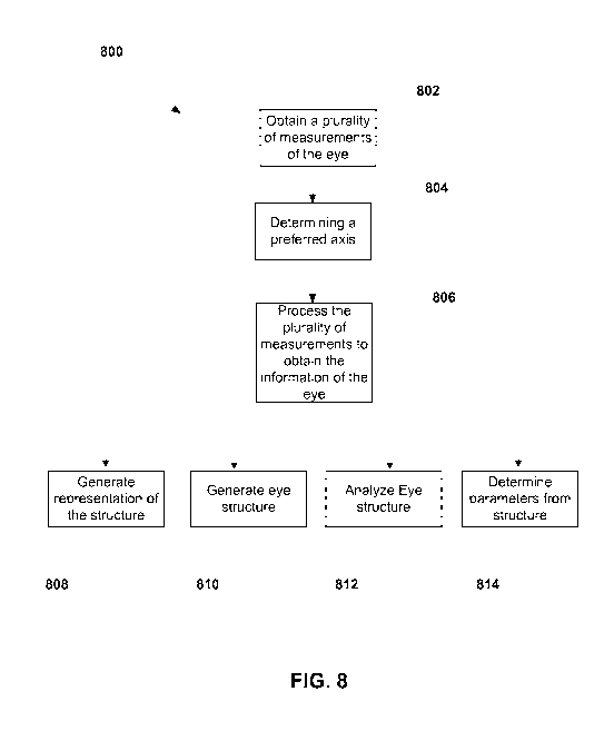
includes
step 808, where a 2D or 3D representations of the eye structure is generated.
In step 810, the
eye structure can be generated based on the 2D or 3D representations. In step
812, the eye
structure can be analyzed to determine various features in the eye. In step
814, various
parameters of the eye can be determined from images of the various features of
the eye
determined in step 812.
[0068] The representations can include, for example, the cornea 340, the
anterior corneal
surface 361, the posterior corneal surface 362, the anterior chamber 363, the
lens 364, the
anterior lens surface 365, the posterior lens surface 366, and the retina 410
(including the
anterior retina surface and the posterior retina surface) of the eye by
processing the optical
reflections from the corresponding regions of the eye. In some embodiments,
the cornea
vertex normal, visual axis, or a line-of-sight can be determined using the
representations. In
some embodiments, the fovea of the eye can be determined from the
representations by
forming an image. In some embodiments, the cornea of the eye can be located
and curve
fitting can be applied to determine the highest reflection, calculate an
average, median, or
other statistical functions of the optical reflections of the cornea.
Similarly, the retina of the
eye can be determined by spatially averaging, curve fitting of the optical
reflections from the
retina, using the optical reflection from the retina along the axis of the
corneal vertex normal,
or by selecting the strongest reflection at or near the center of the fovea.
The axial length of
the eye can be determined by calculating the distance between the location of
the cornea and
the location of the retina.
[0069] Further, corneal thickness can be determined from the eye
structure generated by
locating the optical reflections from the anterior cornea surface and the
posterior cornea
surface at or near the vertex normal, spatially averaging or curve fitting the
optical reflections
22
CA 02866577 2014-09-05
WO 2013/134554
PCT/US2013/029703
from the anterior corneal surface and the posterior corneal surface. By curve
fitting, the
curvature of the anterior corneal surface can be determined from the optical
reflections from
the anterior corneal surface. Further, the anterior chamber depth can be
determined from the
distance between the optical reflections from the anterior corneal surface or
the posterior
corneal surface and the anterior lens. The thickness of the lens can be
determined from the
distance between the optical reflections from the anterior lens and the
posterior lens. A
vitreous thickness of the eye can be determined from the distance between the
optical
reflections from the posterior lens and the retina. The thickness of the
retina can be
determined from the distance between the optical reflections from the anterior
retina and the
posterior retina. The distances to the anterior cornea, the posterior corneal
surface, and the
retina can be obtained simultaneously. A full-range A-scan can be generated by
combining
measurements of distance from the anterior corneal surface, the thickness of
the cornea, the
depth of the anterior chamber, the thickness of the lens and the retina by
using the optical
reflections from the corresponding regions.
[0070] It should be appreciated that alternative and modifications apparent
to one of
ordinary skills in the art can be applied within the scope of the present
inventions. For
example, the size, the spacing, the locations and arrangement of the scan
array pattern, the
lens combinations for wide-field corneal and retinal images can be varied from
the specific
embodiments disclosed herein.
23