Note: Descriptions are shown in the official language in which they were submitted.
CA 02866672 2014-09-05
WO 2013/120115 PCT/US2013/035506
MOTION PICTURE PROJECT MANAGEMENT SYSTEM
This application is a continuation in part of U.S. Utility Patent Application
Serial No.
13/029,862, filed 17 February 2011, which is a continuation in part of U.S.
Utility Patent
Application Serial No. 12/976,970, filed 22 December 2010, which is a
continuation in part of
U.S. Utility Patent Application Serial No. 12/913,614, filed 27 October 2010,
which is a
continuation in part of U.S. Utility Patent Application Serial No. 12/542,498,
filed 17 August
2009, which is a continuation in part of U.S. Utility Patent Application
Serial No. 12/032,969,
filed 18 February 2008 and issued as U.S. Patent 7,577,312, which is a
continuation of U.S.
Patent 7,333,670, filed 4 January 2006, which is a divisional of U.S. Patent
7,181,081, filed June
18th, 2003 which is a national stage entry of Patent Cooperation Treaty
Application Serial No.
PCT/U502/14192, filed May 6th, 2003, which claims the benefit of United States
Provisional
Patent Application 60/288,929, filed May 4th, 2001, the specifications of
which are all hereby
incorporated herein by reference.
BACKGROUND OF THE INVENTION
FIELD OF THE INVENTION
[001] One or more embodiments of the invention are related to the field of
project management
in the motion picture industry and relates to reviewers, production managers
who manage artists.
Production managers are also known as "production" for short. Artists utilize
image analysis and
image enhancement and computer graphics processing for example to convert two-
dimensional
images into three-dimensional images associated with a motion picture or
otherwise create or
alter motion pictures. More particularly, but not by way of limitation, one or
more embodiments
of the invention enable motion picture project management system configured to
efficiently
manage projects related to motion pictures to manage assets, control costs,
predict budgets and
profit margins, reduce archival storage and otherwise provide displays
tailored to specific roles to
increase worker efficiency.
DESCRIPTION OF THE RELATED ART
[002] Known methods for the colorizing of black and white feature films
involves the
identification of gray scale regions within a picture followed by the
application of a pre-selected
color transform or lookup tables for the gray scale within each region defined
by a masking
1
CA 02866672 2014-09-05
WO 2013/120115 PCT/US2013/035506
operation covering the extent of each selected region and the subsequent
application of said
masked regions from one frame to many subsequent frames. The primary
difference between US
Patent No. 4,984,072, System And Method For Color Image Enhancement, and US
Patent No.
3,705,762, Method For Converting Black-And-White Films To Color Films, is the
manner by
which the regions of interest (ROIs) are isolated and masked, how that
information is transferred
to subsequent frames and how that mask information is modified to conform with
changes in the
underlying image data. In the 4,984,072 system, the region is masked by an
operator via a one-bit
painted overlay and operator manipulated using a digital paintbrush method
frame by frame to
match the movement. In the 3,705,762 process, each region is outlined or
rotoscoped by an
operator using vector polygons, which are then adjusted frame by frame by the
operator, to create
animated masked ROIs. Various masking technologies are generally also utilized
in the
conversion of 2D movies to 3D movies.
[003] In both systems described above, the color transform lookup tables and
regions selected
are applied and modified manually to each frame in succession to compensate
for changes in the
image data that the operator detects visually. All changes and movement of the
underlying
luminance gray scale is subjectively detected by the operator and the masks
are sequentially
corrected manually by the use of an interface device such as a mouse for
moving or adjusting
mask shapes to compensate for the detected movement. In all cases the
underlying gray scale is a
passive recipient of the mask containing pre-selected color transforms with
all modifications of
the mask under operator detection and modification. In these prior inventions
the mask
information does not contain any information specific to the underlying
luminance gray scale and
therefore no automatic position and shape correction of the mask to correspond
with image
feature displacement and distortion from one frame to another is possible.
[004] Existing systems that are utilized to convert two-dimensional images to
three-dimensional
images may also require the creation of wire frame models for objects in
images that define the
3D shape of the masked objects. The creation of wire frame models is a large
undertaking in
terms of labor. These systems also do not utilize the underlying luminance
gray scale of objects
in the images to automatically position and correct the shape of the masks of
the objects to
correspond with image feature displacement and distortion from one frame to
another. Hence,
great amounts of labor are required to manually shape and reshape masks for
applying depth or
Z-dimension data to the objects. Motion objects that move from frame to frame
thus require a
great deal of human intervention. In addition, there are no known solutions
for enhancing two-
dimensional images into three-dimensional images that utilize composite
backgrounds of
multiple images in a frame for spreading depth information to background and
masked objects.
2
CA 02866672 2014-09-05
WO 2013/120115 PCT/US2013/035506
This includes data from background objects whether or not pre-existing or
generated for an
occluded area where missing data exists, i.e., where motion objects never
uncover the
background. In other words, known systems gap fill using algorithms for
inserting image data
where none exists, which causes artifacts.
[005] Current methods for converting movies from 2D to 3D that include
computer-generated
elements or effects, generally utilize only the final sequence of 2D images
that make up the
movie. This is the current method used for conversion of all movies from two-
dimensional data
to left and right image pairs for three-dimensional viewing. There are no
known current methods
that obtain and make use of metadata associated with the computer-generated
elements for a
movie to be converted. This is the case since studios that own the older 2D
movies may not have
retained intermediate data for a movie, i.e., the metadata associated with
computer generated
elements, since the amount of data in the past was so large that the studios
would only retain the
final movie data with rendered computer graphics elements and discard the
metadata. For
movies having associated metadata that has been retained, (i.e., intermediate
data associated with
the computer-generated elements such as mask, or alpha and/or depth
information), use of this
metadata would greatly speed the depth conversion process.
[006] In addition, typical methods for converting movies from 2D to 3D in an
industrial setting
capable of handling the conversion of hundreds of thousands of frames of a
movie with large
amounts of labor or computing power, make use of an iterative workflow. The
iterative
workflow includes masking objects in each frame, adding depth and then
rendering the frame
into left and right viewpoints forming an anaglyph image or a left and right
image pair. If there
are errors in the edges of the masked objects for example, then the typical
workflow involves an
"iteration", i.e., sending the frames back to the workgroup responsible for
masking the objects,
(which can be in a country with cheap unskilled labor half way around the
world), after which
the masks are sent to the workgroup responsible for rendering the images,
(again potentially in
another country), after which the rendered image pair is sent back to the
quality assurance group.
It is not uncommon in this workflow environment for many iterations of a
complicated frame to
take place. This is known as "throw it over the fence" workflow since
different workgroups
work independently to minimize their current work load and not as a team with
overall efficiency
in mind. With hundreds of thousands of frames in a movie, the amount of time
that it takes to
iterate back through frames containing artifacts can become high, causing
delays in the overall
project. Even if the re-rendering process takes place locally, the amount of
time to re-render or
ray-trace all of the images of a scene can cause significant processing and
hence delays on the
order of at least hours. Elimination of iterations such as this would provide
a huge savings in
3
CA 02866672 2014-09-05
WO 2013/120115 PCT/US2013/035506
wall-time, or end-to-end time that a conversion project takes, thereby
increasing profits and
minimizing the workforce needed to implement the workflow.
[007] General simplistic project management concepts are known, however the
formal and
systematic application of project management in engineering projects of large
complexity began
in the mid-1900's. Project management in general involves at least planning
and managing
resources and workers to complete a temporary activity known as a project.
Projects are
generally time oriented and also constrained by scope and budget. Project
management was first
described in a systematic manner by Frederick Winslow Taylor and his students
Henry Gantt and
Henri Fayol. Work breakdown structure and Gantt charts were used initially and
Critical Path
Method "CPM" and Program Evaluation and Review Technique "PERT" were later
developed in
industrial and defense settings respectively.
Project cost estimating followed these
developments. Basic project management generally includes initiation, project
planning,
execution, monitor/control and completion. More complex project management
techniques may
attempt to achieve other goals, such as ensuring that the management process
is defined,
quantitatively managed and optimized for example as is described in the
Capability Maturity
Model Integration approach.
[008] As described above, industrial based motion picture projects typically
include hundreds of
thousands of frames, however in addition, these types of projects may also
utilize use gigantic
amounts of storage including potentially hundreds of layers of masks and
images per frame and
hundreds of workers. These types of projects have been managed in a fairly ad
hoc manner to
date in which costs are difficult to predict, controlled feedback to redirect
a project toward
financial success, asset management and most other best practice project
management techniques
are minimally utilized. In addition, project management tools utilized include
off the shelf
project management tools that are not tailored for the specifics of project
management in a
unique vertical industry such as motion picture effects and conversion
projects. Hence,
predicting costs and quality and repeatedly performing projects in the film
industry has been
difficult to accomplish to date. For example, existing motion picture projects
sometimes require
three people to review an edited frame in some cases, e.g., a person to locate
the resource
amongst a large number of resources, a person to review the resource and
another person to
provide annotations for feedback and rework. Although standalone tools exist
to perform these
tasks, they are generally not integrated and are difficult for personnel in
different roles to utilize.
[009] Regardless of the known techniques, there are no known optimizations or
implementations
of project management solutions that take into account the unique requirements
of the motion
picture industry. Hence there is a need for a motion picture project
management system.
4
CA 02866672 2014-09-05
WO 2013/120115 PCT/US2013/035506
BRIEF SUMMARY OF THE INVENTION
[0010] Embodiments of the invention generally are directed at project
management related to the
production, processing or conversion of motion pictures. Large motion picture
projects generally
utilize workers of several roles to process each image that makes up a motion
picture, which may
number in the hundreds of thousands of image frames. One or more embodiments
of the
invention enables a computer and database to be configured to accept the
assignment of tasks
related to artists, time entries for tasks by artists and review of time and
actuals of artists by
coordinators, a.k.a., "production" and the review of work product by editorial
roles. The system
thus enables artists working on shots made up of multiple images to be managed
for successful
on-budget completion of projects, along with minimization of generally vast
storage
requirements for motion picture assets and enable prediction of costs for
future bidding on
projects given quality, ratings of workers to use and schedule.
[0011] Tasks involved in a motion picture project generally include tasks
related to assessment
of a project, ingress of a project, assignment of tasks, performing the
assigned tasks or project
work, reviewing the work product and archiving and shipping the work product
of the project.
One or more embodiments of the invention enable workers of different "roles"
to view project
tasks in a manner consistent with and which aids their role. This is unknown
in the motion
picture industry. Roles may be utilized in one or more embodiments of the
invention that
include "editorial", "asset manager", "visual effects supervisor",
"coordinator" or "production",
"artist", "lead artist", "stereographer", "compositor", "reviewer",
"production assistant". In a
simpler sense for ease of illustration, three general categories relate to
production workers that
manage artists, artist workers who perform the vast majority of work product
related work and
editorial workers who review and provide feedback based on the work product.
Each of these
roles may utilize a unique or shared view of the motion picture image frames
and/or information
related to each image or other asset that their role is assigned to work on.
[0012] General Workflow for the Assessment phase
[0013] Generally, the editorial and/or asset manager and/or visual effects
supervisor roles utilize
a tool that shows the motion picture on a display of a computer. The tool, for
example enables
the various roles involved in this phase to break a motion picture down into
scenes or shots to be
worked on. One such tool includes "FRAME CYCLER " commercially available from
ADOBE .
[0014] General Workflow for the Ingest phase
CA 02866672 2014-09-05
WO 2013/120115 PCT/US2013/035506
[0015] Generally, the asset manager enters the various scene breaks and other
resource such as
alpha masks, computer generated element layers or any other resources
associated with scenes in
the motion picture into a database. Any type of database may be utilized in
one or more
embodiments of the invention. One such tool that may be utilized to store
information related to
the motion picture and the assets for project management includes the project
management
database "TACTICTm", which is commercially available from SOUTHPAW TECHNOLOGY
Inc.TM. Any database may be utilized in one or more embodiments of the
invention so long as
the motion picture specific features are included in the project management
database. One or
more embodiments of the invention update the "snapshot" and "file" tables in
the project
management database. The schema of the project management database is briefly
described in
this section and described in more detail in the detailed description section
below.
[0016] General Workflow for the Assignment Phase
[0017] Generally, production workers utilize an interface that couples with
project management
database to assign particular workers to particular tasks associated with
their role and assign the
workers images associated with shots or scenes in a given motion picture. One
or more
embodiments of the invention make use of basic project management database
digital asset
management tables and add additional fields that improve upon basic project
management
functionality to optimize the project management process for the motion
picture industry. One or
more embodiments of the invention update the "task" table in the project
management database.
[0018] General Workflow for the Project Work Phase
[0019] Generally, artists, stereographers and compositors perform a large
portion of the total
work on a motion picture. These roles generally utilize a time clock tool to
obtain their tasks and
set task status and start and stop times for the task. Generally, artists
perform mask and region
design and initial depth augmentation of a frame. The artists generally
utilize a ray tracing
program that may include automated mask tracking capabilities for example,
along with
NUKETM commercially available from "THE FOUNDRYTm, for mask cleanup for
example.
Once a client approves the visual effects and/or depth work on a scene, then
compositors finish
the scene with the same tools that the artists use and generally with other
tools such as AFTER
EFFECTS and PHOTOSHOPO, commercially available from ADOBE . In one or more
embodiments of the invention, the person who worked on a particular asset is
stored in the
project management database in custom fields for example.
[0020] In specific workflow scenarios, workers in region design for example
classify elements
6
CA 02866672 2014-09-05
WO 2013/120115 PCT/US2013/035506
in scenes into two separate categories. Scenes generally include two or more
images in time
sequence for example. The two categories include background elements (i.e.
sets and foreground
elements that are stationary) or motion elements (e.g., actors, automobiles,
etc.) that move
throughout the scene. These background elements and motion elements are
treated separately in
embodiments of the invention similar to the manner in which traditional
animation is produced.
In addition, many movies now include computer-generated elements (also known
as computer
graphics or CG, or also as computer-generated imagery or CGI) that include
objects that do not
exist in reality, such as robots or spaceships for example, or which are added
as effects to
movies, for example dust, fog, clouds, etc. Computer-generated elements may
include
background elements, or motion elements.
[0021] Motion Elements: The motion elements are displayed as a series of
sequential tiled frame
sets or thumbnail images complete with background elements. The motion
elements are masked
in a key frame using a multitude of operator interface tools common to paint
systems as well as
unique tools such as relative bimodal thresholding in which masks are applied
selectively to
contiguous light or dark areas bifurcated by a cursor brush. After the key
frame is fully designed
and masked, the mask information from the key frame is then applied to all
frames in the display-
using mask fitting techniques that include:
[0022] 1. Automatic mask fitting using Fast Fourier Transform and Gradient
Decent
Calculations based on luminance and pattern matching which references the same
masked area of
the key frame followed by all prior subsequent frames in succession. Since the
computer system
implementing embodiments of the invention can reshape at least the outlines of
masks from
frame to frame, large amounts of labor can be saved from this process that
traditionally has been
done by hand. In 2D to 3D conversion projects, sub-masks can be adjusted
manually within a
region of interest when a human recognizable object rotates for example, and
this process can be
"tweened" such that the computer system automatically adjusts sub-masks from
frame to frame
between key frames to save additional labor.
[0023] 2. Bezier curve animation with edge detection as an automatic animation
guide
[0024] 3. Polygon animation with edge detection as an automatic animation
guide
[0025] In one or more embodiments of the invention, computer-generated
elements are imported
using RGBAZ files that include an optional alpha mask and/or depths on a pixel-
by-pixel, or sub-
pixel-by-sub-pixel basis for a computer-generated element. Examples of this
type of file include
the EXR file format. Any other file format capable of importing depth and/or
alpha information
7
CA 02866672 2014-09-05
WO 2013/120115 PCT/US2013/035506
is in keeping with the spirit of the invention. Embodiments of the invention
import any type of
file associated with a computer-generated element to provide instant depth
values for a portion of
an image associated with a computer-generated element. In this manner, no mask
fitting or
reshaping is required for any of the computer-generated elements from frame to
frame since the
alpha and depth on a pixel-by-pixel or sub-pixel-by-sub-pixel basis already
exists, or is otherwise
imported or obtained for the computer-generated element. For complicated
movies with large
amounts of computer-generated elements, the import and use of alpha and depth
for computer-
generated elements makes the conversion of a two-dimensional image to a pair
of images for
right and left eye viewing economically viable. One or more embodiments of the
invention
allow for the background elements and motion elements to have depths
associated with them or
otherwise set or adjusted, so that all objects other than computer-generated
objects are artistically
depth adjusted. In addition, embodiments of the invention allow for the
translation, scaling or
normalization of the depths for example imported from an RGBAZ file that are
associated with
computer-generated objects so as to maintain the relative integrity of depth
for all of the elements
in a frame or sequence of frames. In addition, any other metadata such as
character mattes or
alphas or other masks that exist for elements of the images that make up a
movie can also be
imported and utilized to improve the operated-defined masks used for
conversion. On format of
a file that may be imported to obtain metadata for photographic elements in a
scene includes the
RGBA file format. By layering different objects from deepest to closest, i.e.,
"stacking" and
applying any alpha or mask of each element, and translating the closest
objects the most
horizontally for left and right images, a final pair of depth enhanced images
is thus created based
on the input image and any computer-generated element metadata.
[0026] In another embodiment of this invention, these background elements and
motion
elements are combined separately into single frame representations of multiple
frames, as tiled
frame sets or as a single frame composite of all elements (i.e., including
both motion and
backgrounds/foregrounds) that then becomes a visual reference database for the
computer
controlled application of masks within a sequence composed of a multiplicity
of frames. Each
pixel address within the reference visual database corresponds to mask/lookup
table address
within the digital frame and X, Y, Z location of subsequent "raw" frames that
were used to create
the reference visual database. Masks are applied to subsequent frames based on
various
differentiating image processing methods such as edge detection combined with
pattern
recognition and other sub-mask analysis, aided by operator segmented regions
of interest from
reference objects or frames, and operator directed detection of subsequent
regions corresponding
to the original region of interest. In this manner, the gray scale actively
determines the location
and shape of each mask (and corresponding color lookup from frame to frame for
colorization
8
CA 02866672 2014-09-05
WO 2013/120115 PCT/US2013/035506
projects or depth information for two-dimensional to three-dimensional
conversion projects) that
is applied in a keying fashion within predetermined and operator-controlled
regions of interest.
[0027] Camera Pan Background and Static Foreground Elements: Stationary
foreground and
background elements in a plurality of sequential images comprising a camera
pan are combined
and fitted together using a series of phase correlation, image fitting and
focal length estimation
techniques to create a composite single frame that represents the series of
images used in its
construction. During the process of this construction the motion elements are
removed through
operator adjusted global placement of overlapping sequential frames.
[0028] For colorization projects, the single background image representing the
series of camera
pan images is color designed using multiple color transform look up tables
limited only by the
number of pixels in the display. This allows the designer to include as much
detail as desired
including air brushing of mask information and other mask application
techniques that provide
maximum creative expression. For depth conversion projects, (i.e., two-
dimensional to three-
dimensional movie conversion for example), the single background image
representing the series
of camera pan images may be utilized to set depths of the various items in the
background. Once
the background color/depth design is completed the mask information is
transferred
automatically to all the frames that were used to create the single composited
image. In this
manner, color or depth is performed once per multiple images and/or scene
instead of once per
frame, with color/depth information automatically spread to individual frames
via embodiments
of the invention. Masks from colorization projects may be combined or grouped
for depth
conversion projects since the colorization masks may contain more sub-areas
than a depth
conversion mask. For example, for a coloration project, a person's face may
have several masks
applied to areas such as lips, eyes, hair, while a depth conversion project
may only require an
outline of the person's head or an outline of a person's nose, or a few
geometric shape sub-masks
to which to apply depth. Masks from a colorization project can be utilized as
a starting point for
a depth conversion project since defining the outlines of human recognizable
objects by itself is
time consuming and can be utilized to start the depth conversion masking
process to save time.
Any computer-generated elements at the background level may be applied to the
single
background image.
[0029] In one or more embodiments of the invention, image offset information
relative to each
frame is registered in a text file during the creation of the single composite
image representing
the pan and used to apply the single composite mask to frames used to create
the composite
image.
9
CA 02866672 2014-09-05
WO 2013/120115 PCT/US2013/035506
[0030] Since the foreground moving elements have been masked separately prior
to the
application of the background mask, the background mask information is applied
wherever there
is no pre-existing mask information.
[0031] Static Camera Scenes With and Without Film Weave, Minor Camera
Following and
Camera Drift: In scenes where there is minor camera movement or film weave
resulting from the
sprocket transfer from 35mm or 16mm film to digital format, the motion objects
are first fully
masked using the techniques listed above. All frames in the scene are then
processed
automatically to create a single image that represents both the static
foreground elements and
background elements, eliminating all masked moving objects where they both
occlude and
expose the background.
[0032] Wherever the masked moving object exposes the background or foreground,
the instance
of background and foreground previously occluded is copied into the single
image with priority
and proper offsets to compensate for camera movement. The offset information
is included in a
text file associated with each single representation of the background so that
the resulting mask
information can be applied to each frame in the scene with proper mask
offsets.
[0033] The single background image representing the series of static camera
frames is color
designed using multiple color transform look up tables limited only by the
number of pixels in
the display. Where the motion elements occlude the background elements
continuously within
the series of sequential frames they are seen as black figure that are ignored
and masked over.
The black objects are ignored in colorization-only projects during the masking
operation because
the resulting background mask is later applied to all frames used to create
the single
representation of the background only where there is no pre-existing mask. If
background
information is created for areas that are never exposed, then this data is
treated as any other
background data that is spread through a series of images based on the
composite background.
This allows for minimization of artifacts or artifact-free two-dimensional to
three-dimensional
conversion since there is never any need to stretch objects or extend pixels
as for missing data,
since image data that has been generated to be believable to the human
observer is generated for
and then taken from the occluded areas when needed during the depth conversion
process.
Hence for motion elements and computer-generated elements, realistic looking
data can be
utilized for areas behind these elements when none exists. This allows the
designer to include as
much detail as desired including air brushing of mask information and other
mask application
techniques that provide maximum creative expression. Once the background color
design is
completed the mask information is transferred automatically to all the frames
that were used to
create the single composited image. For depth projects, the distance from the
camera to each
CA 02866672 2014-09-05
WO 2013/120115 PCT/US2013/035506
item in the composite frame is automatically transferred to all the frames
that were used to create
the single composited image. By shifting masked background objects
horizontally more or less,
their perceived depth is thus set in a secondary viewpoint frame that
corresponds to each frame in
the scene. This horizontal shifting may utilize data generated by an artist
for the occluded or
alternatively, areas where no image data exists yet for a second viewpoint may
be marked in one
or more embodiments of the invention using a user defined color that allows
for the creation
missing data to ensure that no artifacts occur during the two-dimension to
three-dimension
conversion process. Any technique known may be utilized in embodiments of the
invention to
cover areas in the background where unknown data exists, i.e., (as displayed
in some color that
shows where the missing data exists) that may not be borrowed from another
scene/frame for
example by having artists create complete backgrounds or smaller occluded
areas with artist
drawn objects. After assigning depths to objects in the composite background,
or by importing
depths associated with computer-generated elements at the background depth, a
second
viewpoint image may be created for each image in a scene in order to produce a
stereoscopic
view of the movie, for example a left eye view where the original frames in
the scene are
assigned to the right eye viewpoint, for example by translating foreground
objects horizontally
for the second viewpoint, or alternatively by translating foreground objects
horizontally left and
right to create two viewpoints offset from the original viewpoint.
[0034] One or more tools employed by the system enable real-time editing of 3D
images without
re-rendering for example to alter layers/colors/masks and/or remove artifacts
and to minimize or
eliminate iterative workflow paths back through different workgroups by
generating translation
files that can be utilized as portable pixel-wise editing files. For example,
a mask group takes
source images and creates masks for items, areas or human recognizable objects
in each frame of
a sequence of images that make up a movie. The depth augmentation group
applies depths, and
for example shapes, to the masks created by the mask group. When rendering an
image pair, left
and right viewpoint images and left and right translation files may be
generated by one or more
embodiments of the invention. The left and right viewpoint images allow 3D
viewing of the
original 2D image. The translation files specify the pixel offsets for each
source pixel in the
original 2D image, for example in the form of UV or U maps. These files are
generally related to
an alpha mask for each layer, for example a layer for an actress, a layer for
a door, a layer for a
background, etc. These translation files, or maps are passed from the depth
augmentation group
that renders 3D images, to the quality assurance workgroup. This allows the
quality assurance
workgroup (or other workgroup such as the depth augmentation group) to perform
real-time
editing of 3D images without re-rendering for example to alter
layers/colors/masks and/or
remove artifacts such as masking errors without delays associated with
processing time/re-
11
CA 02866672 2014-09-05
WO 2013/120115 PCT/US2013/035506
rendering and/or iterative workflow that requires such re-rendering or sending
the masks back to
the mask group for rework, wherein the mask group may be in a third world
country with
unskilled labor on the other side of the globe. In addition, when rendering
the left and right
images, i.e., 3D images, the Z depth of regions within the image, such as
actors for example, may
also be passed along with the alpha mask to the quality assurance group, who
may then adjust
depth as well without re-rendering with the original rendering software. This
may be performed
for example with generated missing background data from any layer so as to
allow
"downstream" real-time editing without re-rendering or ray-tracing for
example. Quality
assurance may give feedback to the masking group or depth augmentation group
for individuals
so that these individuals may be instructed to produce work product as desired
for the given
project, without waiting for, or requiring the upstream groups to rework
anything for the current
project. This allows for feedback yet eliminates iterative delays involved
with sending work
product back for rework and the associated delay for waiting for the reworked
work product.
Elimination of iterations such as this provide a huge savings in wall-time, or
end-to-end time that
a conversion project takes, thereby increasing profits and minimizing the
workforce needed to
implement the workflow.
[0035] General Workflow for the Review Phase
[0036] Regardless of the type of project work performed on a given asset, the
asset is reviewed
for example using an interface that couples with the project management
database to enable the
viewing of work product. Generally, editorial role based users use the
interface most, artists and
stereographers less and lead artists the least. The review notes and images
may be viewed
simultaneously, for example with a clear background surrounding text that is
overlaid on the
image or scene to enable rapid review and feedback by a given worker having a
particular role.
Other improvements to the project management database include ratings or
artists and difficulty
of the asset. These fields enable workers to be rated and projected costs to
be forecast when
bidding projects, which is unknown in the field of motion picture project
planning.
[0037] General Workflow for the Archive and Shipping Phase
[0038] Asset managers may delete and/or compress all assets that may be
regenerated, which
can save hundreds of terabytes of disk space for a typical motion picture.
This enables an
enormous savings in disk drive hardware purchases and is unknown in the art.
[0039] One or more embodiments of the system may be implemented with a
computer and a
database coupled with the computer. Any computer architecture having any
number of
12
CA 02866672 2014-09-05
WO 2013/120115 PCT/US2013/035506
computers, for example coupled via a computer communication network is in
keeping with the
spirit of the invention. The database coupled with the computer includes at
least a project table,
shot table, task table and timesheet table. The project table generally
includes project identifier
and description of a project related to a motion picture. The shot table
generally includes a shot
identifier and references a plurality of images with a starting frame value
and an ending frame
value wherein the plurality of images are associated with the motion picture
that is associated
with the project. The shot table generally includes at least one shot having
status related to
progress of work performed on the shot. The task table generally references
the project using a
project identifier in also located in the project table. The task table
generally includes at least
one task which generally includes a task identifier and an assigned worker,
e.g., artist, and which
may also include a context setting associated with a type of task related to
motion picture work
selected from region design, setup, motion, composite, and review. The at
least one task
generally includes a time allocated to complete the at least one task. The
timesheet item table
generally references the project identifier in the project table and the task
identifier in the task
table. The task table generally includes at least one timesheet item that
includes a start time and
an end time. In one or more embodiments of the invention, the computer is
configured to present
a first display configured to be viewed by an artist that includes at least
one daily assignment
having a context, project, shot and a status input that is configured to
update the status in the task
table and a timer input that is configured to update the start time and the
end time in the
timesheet item table. The computer is generally configured to present a second
display
configured to be viewed by a coordinator or "production" worker, i.e.,
production that includes a
search display having a context, project, shot, status and artist and wherein
the second display
further includes a list of a plurality of artists and respective status and
actuals based on time spent
in the at least one timesheet item versus the time allocated per the at least
one task associated
with the at least one shot. The computer is generally also configured to
present a third display
configured to be viewed by an editor that includes an annotation frame
configured to accept
commentary or drawing or both commentary and drawing on the at least one of
said plurality of
images associated with the at least one shot. One or more embodiments of the
computer may be
configured to provide the third display configured to be viewed by an editor
that includes an
annotation overlaid on at least one of the plurality of images. This
capability provides
information on one display that has generally required three workers to
integrate in known
systems, and which is novel in and of itself.
[0040] Embodiments of the database may also include a snapshot table which
includes an
snapshot identifier and search type and which includes a snapshot of the at
least one shot, for
example that includes a subset of the at least one shot wherein the snapshot
is cached on the
13
CA 02866672 2014-09-05
WO 2013/120115 PCT/US2013/035506
computer to reduce access to the shot table. Embodiments may also include
other context
settings for other types of task categories, for example source and cleanup
related tasks. Any
other context settings or values that are related to motion picture work may
also be included in
keeping with the spirit of the invention. Embodiments of the database may also
include an asset
request table that includes an asset request identifier and shot identifier
that may be utilized to
request work on assets or assets themselves to be worked on or created by
other workers for
example. Embodiments of the database may also include a request table that
includes an mask
request identifier and shot identifier and that may be utilized to request any
type of action by
another worker for example. Embodiments of the database may also include a
note table which
includes a note identifier and that references the project identifier and that
includes at least one
note related to at least one of the plurality of images from the motion
picture. Embodiments of
the database may also include a delivery table that includes a delivery
identifier that references
the project identifier and which includes information related to delivery of
the motion picture.
[0041] One or more embodiments of the computer are configured to accept a
rating input from
production or the editor based on work performed by the artist, optionally in
a blind manner in
which the reviewer does not know the identity of the artist in order to
prevent favoritism for
example. One or more embodiments of the computer are configured to accept a
difficulty of the
at least one shot and calculate a rating based on work performed by the artist
and based on the
difficulty of the shot and time spent on the shot. One or more embodiments of
the computer are
configured to accept a rating input from production or editorial, (i.e., an
editor worker) based on
work performed by the artist, or, accept a difficulty of the at least one shot
and calculate a rating
based on work performed by the artist and based on the difficulty of the shot
and time spent on
the shot, and, signify an incentive with respect to the artist based on the
rating accepted by the
computer or calculated by the computer. One or more embodiments of the
computer are
configured to estimate remaining cost based on the actuals that are based on
total time spent for
all of the at least one tasks associated with all of the at least one shot in
the project versus time
allocated for all of the at least one tasks associated with all of the at
least one shot in the project.
One or more embodiments of the computer are configured to compare the actuals
associated with
a first project with actuals associated with a second project and signify at
least one worker to be
assigned from the first project to the second project based on at least one
rating of the first
worker that is assigned to the first project. One or more embodiments of the
computer are
configured to analyze a prospective project having a number of shots and
estimated difficulty per
shot and based on actuals associated with the project, calculate a predicted
cost for the
prospective project. One or more embodiments of the computer are configured to
analyze a
prospective project having a number of shots and estimated difficulty per shot
and based on the
14
CA 02866672 2014-09-05
WO 2013/120115 PCT/US2013/035506
actuals associated with a first previously performed project and a second
previously performed
project that completed after the first previously performed project, calculate
a derivate of the
actuals, calculate a predicted cost for the prospective project based on the
derivative of the
actuals. For example, as the process improves, tools improve and workers
improve, the
efficiency of work improves and the budgeting and bid processes can take this
into account by
calculating how efficiency is changing versus time and use this rate of change
to predict costs for
a prospective project. One or more embodiments of the computer are configured
to analyze the
actuals associated with said project and divide completed shots by total shots
associated with said
project and present a time of completion of the project. One or more
embodiments of the
computer are configured to analyze the actuals associated with the project and
divide completed
shots by total shots associated with the project, present a time of completion
of the project,
accept an input of at least one additional artist having a rating, accept a
number of shots in which
to use the additional artist, calculate a time savings based on the at least
one additional artist and
the number of shots, subtract the time savings from the time of completion of
the project and
present an updated time of completion of the project. One or more embodiments
of the computer
are configured to calculate amount of disk space that may be utilized to
archive the project and
signify at least one asset that may be rebuilt from other assets to avoid
archival of the at least one
asset. One or more embodiments of the computer are configured to display an
error message if
the artist is working with a frame number that is not current in the at least
one shot. This may
occur when fades, dissolves or other effects lengthen a particular shot for
example wherein the
shot contains frames not in the original source assets.
CA 02866672 2014-09-05
WO 2013/120115 PCT/US2013/035506
BRIEF DESCRIPTION OF THE DRAWINGS
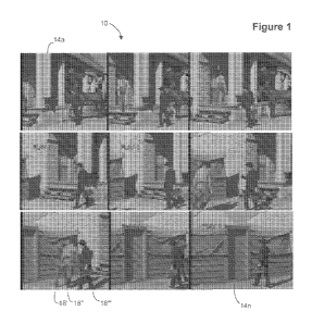
[0042] FIG. 1 shows a plurality of feature film or television film frames
representing a scene or
cut in which there is a single instance or perceptive of a background.
[0043] FIG. 2 shows an isolated background processed scene from the plurality
of frames shown
in FIG. 1 in which all motion elements are removed using various subtraction
and differencing
techniques. The single background image is then used to create a background
mask overlay
representing designer selected color lookup tables in which dynamic pixel
colors automatically
compensate or adjust for moving shadows and other changes in luminance.
[0044] FIG. 3 shows a representative sample of each motion object (M-Object)
in the scene
receives a mask overlay that represents designer selected color lookup tables
in which dynamic
pixel colors automatically compensate or adjust for moving shadows and other
changes in
luminance as the M-Object moves within the scene.
[0045] FIG. 4 shows all mask elements of the scene are then rendered to create
a fully colored
frame in which M-Object masks are applied to each appropriate frame in the
scene followed by
the background mask, which is applied only where there is no pre-existing mask
in a Boolean
manner.
[0046] FIGS. 5A and 5B show a series of sequential frames loaded into display
memory in
which one frame is fully masked with the background (key frame) and ready for
mask
propagation to the subsequent frames via automatic mask fitting methods.
[0047] FIGS. 6A and 6B show the child window displaying an enlarged and
scalable single
image of the series of sequential images in display memory. The Child window
enables the
operator to manipulate masks interactively on a single frame or in multiple
frames during real
time or slowed motion.
[0048] FIGS. 7A and 7B shows a single mask (flesh) is propagated automatically
to all frames in
the display memory.
[0049] FIG. 8 shows all masks associated with the motion object are propagated
to all sequential
frames in display memory.
16
CA 02866672 2014-09-05
WO 2013/120115 PCT/US2013/035506
[0050] FIG. 9A shows a picture of a face.
[0051] FIG. 9B shows a close up of the face in FIG. 9A wherein the "small
dark" pixels shown
in FIG. 9B are used to calculate a weighed index using bilinear interpolation.
[0052] FIGS 10A-D show searching for a Best Fit on the Error Surface: An error
surface
calculation in the Gradient Descent Search method involves calculating mean
squared differences
of pixels in the square fit box centered on reference image pixel (x0, y0),
between the reference
image frame and the corresponding (offset) location (x, y) on the search image
frame.
[0053] FIGS. 11A-C show a second search box derived from a descent down the
error surface
gradient (evaluated separately), for which the evaluated error function is
reduced, possibly
minimized, with respect to the original reference box (evident from visual
comparison of the
boxes with the reference box in FIGS. 10A, B, C and D.).
[0054] FIG. 12 depicts the gradient component evaluation. The error surface
gradient is
calculated as per definition of the gradient. Vertical and horizontal error
deviations are evaluated
at four positions near the search box center position, and combined to provide
an estimate of the
error gradient for that position. 12.
[0055] FIG. 13 shows a propagated mask in the first sequential instance where
there is little
discrepancy between the underlying image data and the mask data. The dress
mask and hand
mask can be clearly seen to be off relative to the image data.
[0056] FIG. 14 shows that by using the automatic mask fitting routine, the
mask data adjusts to
the image data by referencing the underlying image data in the preceding
image.
[0057] FIG. 15 shows the mask data in later images within the sequence show
marked
discrepancy relative to the underlying image data. Eye makeup, lipstick,
blush, hair, face, dress
and hand image data are all displaced relative to the mask data.
[0058] FIG. 16 shows that the mask data is adjusted automatically based on the
underlying
image data from the previous mask and underlying image data.
17
CA 02866672 2014-09-05
WO 2013/120115 PCT/US2013/035506
[0059] FIG. 17 shows the mask data from FIG. 16 is shown with appropriate
color transforms
after whole frame automatic mask fitting. The mask data is adjusted to fit the
underlying
luminance pattern based on data from the previous frame or from the initial
key frame.
[0060] FIG. 18 shows polygons that are used to outline a region of interest
for masking in frame
one. The square polygon points snap to the edges of the object of interest.
Using a Bezier curve
the Bezier points snap to the object of interest and the control points/curves
shape to the edges.
[0061] FIG. 19 shows the entire polygon or Bezier curve is carried to a
selected last frame in the
display memory where the operator adjusts the polygon points or Bezier points
and curves using
the snap function which automatically snaps the points and curves to the edges
of the object of
interest.
[0062] FIG. 20 shows that if there is a marked discrepancy between the points
and curves in
frames between the two frames where there was an operator interactive
adjustment, the operator
will further adjust a frame in the middle of the plurality of frames where
there is maximum error
of fit.
[0063] FIG. 21 shows that when it is determined that the polygons or Bezier
curves are correctly
animating between the two adjusted frames, the appropriate masks are applied
to all frames.
[0064] FIG. 22 shows the resulting masks from a polygon or Bezier animation
with automatic
point and curve snap to edges. The brown masks are the color transforms and
the green masks
are the arbitrary color masks.
[0065] FIG 23 shows an example of two pass blending: The objective in two-pass
blending is to
eliminate moving objects from the final blended mosaic. This can be done by
first blending the
frames so the moving object is completely removed from the left side of the
background mosaic.
As shown in FIG. 23, the character can is removed from the scene, but can
still be seen in the
right side of the background mosaic.
[0066] FIG. 24 shows the second pass blend. A second background mosaic is then
generated,
where the blend position and width is used so that the moving object is
removed from the right
side of the final background mosaic. As shown in FIG. 24, the character can is
removed from the
18
CA 02866672 2014-09-05
WO 2013/120115 PCT/US2013/035506
scene, but can still be seen the left side of the background mosaic. In the
second pass blend as
shown in FIG. 24, the moving character is shown on the left.
[0067] FIG. 25 shows the final background corresponding to FIGS. 23-24. The
two-passes are
blended together to generate the final blended background mosaic with the
moving object
removed from the scene. As shown in FIG. 25, the final blended background with
moving
character is removed.
[0068] FIG. 26 shows an edit frame pair window.
[0069] FIG. 27 shows sequential frames representing a camera pan that are
loaded into memory.
The motion object (butler moving left to the door) has been masked with a
series of color
transform information leaving the background black and white with no masks or
color transform
information applied.
[0070] FIG. 28 shows six representative sequential frames of the pan above are
displayed for
clarity.
[0071] FIG. 29 shows the composite or montage image of the entire camera pan
that was built
using phase correlation techniques. The motion object (butler) included as a
transparency for
reference by keeping the first and last frame and averaging the phase
correlation in two
directions. The single montage representation of the pan is color designed
using the same color
transform masking techniques as used for the foreground object.
[0072] FIG. 30 shows that the sequence of frames in the camera pan after the
background mask
color transforms the montage has been applied to each frame used to create the
montage. The
mask is applied where there is no pre-existing mask thus retaining the motion
object mask and
color transform information while applying the background information with
appropriate offsets.
[0073] FIG. 31 shows a selected sequence of frames in the pan for clarity
after the color
background masks have been automatically applied to the frames where there is
no pre-existing
masks.
[0074] FIG. 32 shows a sequence of frames in which all moving objects (actors)
are masked
with separate color transforms.
19
CA 02866672 2014-09-05
WO 2013/120115 PCT/US2013/035506
[0075] FIG. 33 shows a sequence of selected frames for clarity prior to
background mask
information. All motion elements have been fully masked using the automatic
mask-fitting
algorithm.
[0076] FIG. 34 shows the stationary background and foreground information
minus the
previously masked moving objects. In this case, the single representation of
the complete
background has been masked with color transforms in a manner similar to the
motion objects.
Note that outlines of removed foreground objects appear truncated and
unrecognizable due to
their motion across the input frame sequence interval, i.e., the black objects
in the frame
represent areas in which the motion objects (actors) never expose the
background and
foreground. The black objects are ignored during the masking operation in
colorization-only
projects because the resulting background mask is later applied to all frames
used to create the
single representation of the background only where there is no pre-existing
mask. In depth
conversion projects the missing data area may be displayed so that image data
may be
obtained/generated for the missing data area so as to provide visually
believable image data when
translating foreground objects horizontally to generate a second viewpoint.
[0077] FIG. 35 shows the sequential frames in the static camera scene cut
after the background
mask information has been applied to each frame with appropriate offsets and
where there is no
pre-existing mask information.
[0078] FIG. 36 shows a representative sample of frames from the static camera
scene cut after
the background information has been applied with appropriate offsets and where
there is no pre-
existing mask information.
[0079] FIGS. 37A-C show embodiments of the Mask Fitting functions, including
calculate fit
grid and interpolate mask on fit grid.
[0080] FIGS. 38A-B show embodiments of the extract background functions.
[0081] FIGS. 39A-C show embodiments of the snap point functions.
[0082] FIGS. 40A-C show embodiments of the bimodal threshold masking
functions, wherein
FIG. 40C corresponds to step 2.1 in FIG. 40A, namely "Create Image of
Light/Dark Cursor
CA 02866672 2014-09-05
WO 2013/120115 PCT/US2013/035506
Shape" and FIG. 40B corresponds to step 2.2 in Figure 40A, namely "Apply
Light/Dark shape to
mask".
[0083] FIGS. 41A-B show embodiments of the calculate fit value functions.
[0084] FIG. 42 shows two image frames that are separated in time by several
frames, of a person
levitating a crystal ball wherein the various objects in the image frames are
to be converted from
two-dimensional objects to three-dimensional objects.
[0085] FIG. 43 shows the masking of the first object in the first image frame
that is to be
converted from a two-dimensional image to a three-dimensional image.
[0086] FIG. 44 shows the masking of the second object in the first image
frame.
[0087] FIG. 45 shows the two masks in color in the first image frame allowing
for the portions
associated with the masks to be viewed.
[0088] FIG. 46 shows the masking of the third object in the first image frame.
[0089] FIG. 47 shows the three masks in color in the first image frame
allowing for the portions
associated with the masks to be viewed.
[0090] FIG. 48 shows the masking of the fourth object in the first image
frame.
[0091] FIG. 49 shows the masking of the fifth object in the first image frame.
[0092] FIG. 50 shows a control panel for the creation of three-dimensional
images, including the
association of layers and three-dimensional objects to masks within an image
frame, specifically
showing the creation of a Plane layer for the sleeve of the person in the
image.
[0093] FIG. 51 shows a three-dimensional view of the various masks shown in
FIGS. 43-49,
wherein the mask associated with the sleeve of the person is shown as a Plane
layer that is
rotated toward the left and right viewpoints on the right of the page.
[0094] FIG. 52 shows a slightly rotated view of FIG. 51.
[0095] FIG. 53 shows a slightly rotated view of FIG. 51.
[0096] FIG. 54 shows a control panel specifically showing the creation of a
sphere object for the
crystal ball in front of the person in the image.
21
CA 02866672 2014-09-05
WO 2013/120115 PCT/US2013/035506
[0097] FIG. 55 shows the application of the sphere object to the flat mask of
the crystal ball, that
is shown within the sphere and as projected to the front and back of the
sphere to show the depth
assigned to the crystal ball.
[0098] FIG. 56 shows a top view of the three-dimensional representation of the
first image frame
showing the Z-dimension assigned to the crystal ball shows that the crystal
ball is in front of the
person in the scene.
[0099] FIG. 57 shows that the sleeve plane rotating in the X-axis to make the
sleeve appear to be
coming out of the image more.
[00100] FIG. 58 shows a control panel specifically showing the creation of a
Head object for
application to the person's face in the image, i.e., to give the person's face
realistic depth without
requiring a wire model for example.
[00101] FIG. 59 shows the Head object in the three-dimensional view, too large
and not aligned
with the actual person's head.
[00102] FIG. 60 shows the Head object in the three-dimensional view, resized
to fit the person's
face and aligned, e.g., translated to the position of the actual person's
head.
[00103] FIG. 61 shows the Head object in the three-dimensional view, with the
Y-axis rotation
shown by the circle and Y-axis originating from the person's head thus
allowing for the correct
rotation of the Head object to correspond to the orientation of the person's
face.
[00104] FIG. 62 shows the Head object also rotated slightly clockwise, about
the Z-axis to
correspond to the person's slightly tilted head.
[00105] FIG. 63 shows the propagation of the masks into the second and final
image frame.
[00106] FIG. 64 shows the original position of the mask corresponding to the
person's hand.
[00107] FIG. 65 shows the reshaping of the mask, that can be performed
automatically and/or
manually, wherein any intermediate frames get the tweened depth information
between the first
image frame masks and the second image frame masks.
[00108] FIG. 66 shows the missing information for the left viewpoint as
highlighted in color on
the left side of the masked objects in the lower image when the foreground
object, here a crystal
ball is translated to the right.
22
CA 02866672 2014-09-05
WO 2013/120115 PCT/US2013/035506
[00109] FIG. 67 shows the missing information for the right viewpoint as
highlighted in color on
the right side of the masked objects in the lower image when the foreground
object, here a crystal
ball is translated to the left.
[00110] FIG. 68 shows an anaglyph of the final depth enhanced first image
frame viewable with
Red/Blue 3-D glasses.
[00111] FIG. 69 shows an anaglyph of the final depth enhanced second and last
image frame
viewable with Red/Blue 3-D glasses, note rotation of person's head, movement
of person's hand
and movement of crystal ball.
[00112] FIG. 70 shows the right side of the crystal ball with fill mode
"smear", wherein the
pixels with missing information for the left viewpoint, i.e., on the right
side of the crystal ball are
taken from the right edge of the missing image pixels and "smeared"
horizontally to cover the
missing information.
[00113] FIG. 71 shows a mask or alpha plane, for an actor's upper torso and
head (and
transparent wings). The mask may include opaque areas shown as black and
transparent areas
that are shown as grey areas.
[00114] FIG. 72 shows an occluded area, that corresponds to the actor of FIG.
71, and that
shows an area of the background that is never exposed in any frame in a scene.
This may be a
composite background for example.
[00115] FIG. 73 shows the occluded area artistically rendered to generate a
complete and
realistic background for use in two-dimensional to three-dimensional
conversion, so as to enable
an artifact-free conversion.
[00116] FIG. 73A shows the occluded area partially drawn or otherwise rendered
to generate
just enough of a realistic looking background for use in minimizing artifacts
two-dimensional to
three-dimensional conversion.
[00117] FIG. 74 shows a light area of the shoulder portion on the right side
of FIG. 71 that
represents a gap where stretching (as is also shown in FIG. 70) would be used
when shifting the
foreground object to the left to create a right viewpoint. The dark portion of
the figure is taken
from the background where data is available in at least one frame of a scene.
[00118] FIG. 75 shows an example of the stretching of pixels, i.e., smearing,
corresponding to
the light area in FIG. 74 without the use of a generated background, i.e., if
no background data is
23
CA 02866672 2014-09-05
WO 2013/120115 PCT/US2013/035506
available for an area that is occluded in all frames of a scene.
[00119] FIG. 76 shows a result of a right viewpoint without artifacts on the
edge of the shoulder
of the person wherein the dark area includes pixels available in one or more
frames of a scene,
and generated data for always-occluded areas of a scene.
[00120] FIG. 77 shows an example of a computer-generated element, here a
robot, which is
modeled in three-dimensional space and projected as a two-dimensional image.
If metadata such
as alpha, mask, depth or any combination thereof exists, the metadata can be
utilized to speed the
conversion process from two-dimensional image to a pair of two-dimensional
images for left and
right eye for three-dimensional viewing.
[00121] FIG. 78 shows an original image separated into a background and
foreground elements,
(mountain and sky in the background and soldiers in the bottom left also see
Fig. 79) along with
the imported color and depth of the computer-generated element, i.e., the
robot with depth
automatically set via the imported depth metadata. As shown in the background,
any area that is
covered for the scene can be artistically rendered for example to provide
believable missing data,
as is shown in Fig. 73 based on the missing data of Fig. 73A, which results in
artifact free edges
as shown in Fig. 76 for example.
[00122] FIG. 79 shows masks associated with the photograph of soldiers in the
foreground to
apply depth to the various portions of the soldiers that lie in depth in front
of the computer-
generated element, i.e., the robot. The dashed lines horizontally extending
from the mask areas
show horizontal translation of the foreground objects takes place and where
imported metadata
can be utilized to accurately auto-correct over-painting of depth or color on
the masked objects
when metadata exists for the other elements of a movie. For example, when an
alpha exists for
the objects that occur in front of the computer-generated elements. One type
of file that can be
utilized to obtain mask edge data is a file with alpha file and/or mask data
such as an RGBA file.
[00123] FIG. 80 shows an imported alpha layer which can also be utilized as a
mask layer to
limit the operator defined, and potentially less accurate masks used for
applying depth to the
edges of the three soldiers A, B and C. In addition, a computer-generated
element for dust can be
inserted into the scene along the line annotated as "DUST", to augment the
reality of the scene.
[00124] FIG. 81 shows the result of using the operator-defined masks without
adjustment when
overlaying a motion element such as the soldier on the computer-generated
element such as the
robot. Through use of the alpha metadata of FIG. 80 applied to the operated-
defined mask edges
of FIG. 79, artifact free edges on the overlapping areas is thus enabled.
24
CA 02866672 2014-09-05
WO 2013/120115 PCT/US2013/035506
[00125] FIG. 82 shows a source image to be depth enhanced and provided along
with left and
right translation files and alpha masks so that downstream workgroups may
perform real-time
editing of 3D images without re-rendering for example to alter
layers/colors/masks and/or
remove and/or or adjust depths without iterative workflow paths back to the
original workgroups.
[00126] FIG. 83 shows masks generated by the mask workgroup for the
application of depth by
the depth augmentation group, wherein the masks are associated with objects,
such as for
example human recognizable objects in the source image of FIG. 82.
[00127] FIG. 84 shows areas where depth is applied generally as darker for
nearer objects and
lighter for objects that are further away.
[00128] FIG. 85A shows a left UV map containing translations or offsets in the
horizontal
direction for each source pixel.
[00129] FIG. 85B shows a right UV map containing translations or offsets in
the horizontal
direction for each source pixel.
[00130] FIG. 85C shows a black value shifted portion of the left UV map of
FIG. 85A to show
the subtle contents therein.
[00131] FIG. 85D shows a black value shifted portion of the right UV map of
FIG. 85B to show
the subtle contents therein.
[00132] FIG. 86A shows a left U map containing translations or offsets in the
horizontal
direction for each source pixel.
[00133] FIG. 86B shows a right U map containing translations or offsets in the
horizontal
direction for each source pixel.
[00134] FIG. 86C shows a black value shifted portion of the left U map of FIG.
86A to show the
subtle contents therein.
[00135] FIG. 86D shows a black value shifted portion of the right U map of
FIG. 86B to show
the subtle contents therein.
[00136] FIG. 87 shows known uses for UV maps, wherein a three-dimensional
model is
unfolded so that an image in UV space can be painted onto the 3D model using
the UV map.
[00137] FIG. 88 shows a disparity map showing the areas where the difference
between the left
CA 02866672 2014-09-05
WO 2013/120115 PCT/US2013/035506
and right translation maps is the largest.
[00138] FIG. 89 shows a left eye rendering of the source image of FIG. 82.
[00139] FIG. 90 shows a right eye rendering of the source image of FIG. 82.
[00140] FIG. 91 shows an anaglyph of the images of FIG. 89 and FIG. 90 for use
with Red/Blue
glasses.
[00141] FIG. 92 shows an image that has been masked and is in the process of
depth
enhancement for the various layers.
[00142] FIG. 93 shows a UV map overlaid onto an alpha mask associated with the
actress
shown in FIG. 92 which sets the translation offsets in the resulting left and
right UV maps based
on the depth settings of the various pixels in the alpha mask.
[00143] FIG. 94 shows a workspace generated for a second depth enhancement
program, or
compositing program such as NUKE 0, i.e., generated for the various layers
shown in FIG. 92,
i.e., left and right UV translation maps for each of the alphas wherein the
workspace allows for
quality assurance personnel (or other work groups) to perform real-time
editing of 3D images
without re-rendering for example to alter layers/colors/masks and/or remove
artifacts or
otherwise adjust masks and hence alter the 3D image pair (or anaglyph) without
iteratively
sending fixes to any other workgroup.
[00144] FIG. 95 shows a workflow for iterative corrective workflow.
[00145] FIG. 96 shows an embodiment of the workflow enabled by one or more
embodiments of
the system in that each workgroup can perform real-time editing of 3D images
without re-
rendering for example to alter layers/colors/masks and/or remove artifacts and
otherwise correct
work product from another workgroup without iterative delays associated with
re-rendering/ray-
tracing or sending work product back through the workflow for corrections.
[00146] FIG. 97 illustrates and architectural view of an embodiment of the
invention.
[00147] FIG. 98 illustrates an annotated view of a session manager window
utilized to define a
plurality of images to work on or assign work to.
[00148] FIG. 99 illustrates a view of the production display showing a
project, shots and tasks
related to the selected shot, along with status for each task context
associated with the shot.
26
CA 02866672 2014-09-05
WO 2013/120115 PCT/US2013/035506
[00149] FIG. 100 illustrates a view of the actuals associated with a
particular shot within a
project for each task context associated with the shot wherein "under bid"
task actuals are shown
in a first manner and tasks that are within a predefined percentage within the
bid amount are
shown in a second manner while tasks that are over bid are shown in a third
manner.
[00150] FIG. 101 illustrates the amount of disk space that may be saved by
deleting files which
can be reconstructed from other files, for example after completion of a
project to save disk drive
expenditures.
[00151] FIG. 102 illustrates a view of an artist display showing the task
context, project, shot,
status, tools, start time button, check-in input, rendering input, internal
shot review input, meal,
start/time/stop, review and submit inputs.
[00152] FIG. 103 illustrates an annotated view of the menu bar of the artist
display.
[00153] FIG. 104 illustrates an annotated view of the task row of the artist
display.
[00154] FIG. 105 illustrates an annotated view of the main portion of the user
interface of the
artist display.
[00155] FIG. 106 illustrates a build timeline display for the artist display
for creating a timeline
to work on.
[00156] FIG. 107 illustrates a browse snapshots display for the artist display
that enables an
artist to view the snapshot of a shot or otherwise cache important information
related to a shot so
that the database does not have to field requests for often utilized data.
[00157] FIG. 108 illustrates an artist actual window showing the actuals of
time spent on tasks,
for example versus time allocated for the tasks, with dropdown menus for
specific timesheets.
[00158] FIG. 109 illustrates a notes display for the artist display that
enables artists to enter a
note related to the shot.
[00159] FIG. 110 illustrates a check in display for the artist display that
enables work to be
checked in after work on the shot is complete.
[00160] FIG. 111 illustrates a view of an editorial display showing the
project, filter inputs,
timeline inputs and search results showing the shots in the main portion of
the window along
with the context of work and assigned worker.
27
CA 02866672 2014-09-05
WO 2013/120115 PCT/US2013/035506
[00161] FIG. 112 illustrates a view of the session manager display of the
editorial display for
selecting shots to review.
[00162] FIG. 113 illustrates a view of the advanced search display of the
editorial display.
[00163] FIG. 114 illustrates a view of the simple search display of the
editorial display.
[00164] FIG. 115 illustrates a view of the reviewing pane for a shot also
showing integrated
notes and/or snapshot information in the same frame.
[00165] FIG. 116 illustrates a view of the timelines to select for review
and/or checkin after
modification.
[00166] FIG. 117 illustrates the annotations added to a frame for feedback
using the tool of FIG.
117.
28
CA 02866672 2014-09-05
WO 2013/120115 PCT/US2013/035506
DETAILED DESCRIPTION OF THE INVENTION
[00167] FIG. 97 illustrates and architectural view of an embodiment of the
invention. One or
more embodiments of the system include computer 9702 and database 9701 coupled
with
computer 9702. Any computer architecture having any number of computers, for
example
coupled via a computer communication network is in keeping with the spirit of
the invention.
Database 9701 coupled with computer 9702 includes at least a project table,
shot table, task table
and timesheet table. The project table generally includes project identifier
and description of a
project related to a motion picture. The shot table generally includes a shot
identifier and
references a plurality of images with a starting frame value and an ending
frame value wherein
the plurality of images are associated with the motion picture that is
associated with the project.
The shot table generally includes at least one shot having status related to
progress of work
performed on the shot. The task table generally references the project using a
project identifier in
also located in the project table. The task table generally includes at least
one task which
generally includes a task identifier and an assigned worker, e.g., artist, and
which may also
include a context setting associated with a type of task related to motion
picture work selected
from region design, setup, motion, composite, and review for example (or any
other set of motion
picture related types of tasks). The context setting may also imply or have a
default workflow so
that region design flows into depth which flows into composite. This enables
the system to
assign the next type of task, or context that the shot is to have work
performed on. The flow may
be linear or may iterate back for rework for example. The at least one task
generally includes a
time allocated to complete the at least one task. The timesheet item table
generally references the
project identifier in the project table and the task identifier in the task
table. The task table
generally includes at least one timesheet item that includes a start time and
an end time. The
completion of tasks may in one or more embodiments set the context of the task
to the next task
in sequence in a workflow and the system may automatically notify the next
worker in the
workflow based on the next context of work to be performed and the workers may
work under
different contexts as previously described. In one or more embodiments
contexts may have sub-
contexts, i.e., region design may be broken into masking and outsource masking
while depth may
be broken into key frame and motion contexts, depending on the desired
workflow for the
specific type of operations to be performed on a motion picture project.
[00168] Embodiments of the database may also include a snapshot table which
includes a
snapshot identifier and search type and which includes a snapshot of the at
least one shot, for
example that includes a subset of the at least one shot wherein the snapshot
is cached on the
computer to reduce access to the shot table. Other embodiments of the snapshot
table keep track
29
CA 02866672 2014-09-05
WO 2013/120115 PCT/US2013/035506
of the resources on the network, stores information about the resources and
track versioning of
the resource. Embodiments may also include other context settings for other
types of task
categories, for example source and cleanup related tasks. Any other context
settings or values
that are related to motion picture work may also be included in keeping with
the spirit of the
invention. Embodiments of the database may also include an asset request table
that includes an
asset request identifier and shot identifier that may be utilized to request
work on assets or assets
themselves to be worked on or created by other workers for example.
Embodiments of the
database may also include a request table that includes an mask request
identifier and shot
identifier and that may be utilized to request any type of action by another
worker for example.
Embodiments of the database may also include a note table which includes a
note identifier and
that references the project identifier and that includes at least one note
related to at least one of
the plurality of images from the motion picture. Embodiments of the database
may also include a
delivery table that includes a delivery identifier that references the project
identifier and which
includes information related to delivery of the motion picture.
[00169] One or more embodiments of the database may utilize a schema as
follows or any other
schema that is capable of supporting the functionality of the invention as
specifically
programmed in computer 9702 and as described in any combination or sub-
combination as
follows so long as motion picture project management may be performed as
detailed herein or to
in any other way better manage motion picture projects using the exemplary
specifications
herein:
[00170] PROJECT TABLE
[00171] unique project identifier, project code (text name), title of motion
picture, type of
project (test or for hire), last database update date and time, status
(retired or active), last version
update of the database, project type (colorization, effects, 2D->3D
conversion, feature film,
catalogue), lead worker, review drive (where the review shots are stored).
[00172] TASK TABLE
[00173] unique task identifier, assigned worker, description (what to do),
status (ingested,
waiting, complete, returned, approved), bid start date, bid end date, bid
duration, actual start date,
actual end date, priority, context (stacking, asset, motion, motion visual
effects, outsource,
cleanup, alpha generation, composite, masking, clean plate, setup, keyframe,
quality control),
project code in project table, supervisor or production or editorial worker,
time spent per process.
[00174] SNAPSHOT TABLE
CA 02866672 2014-09-05
WO 2013/120115 PCT/US2013/035506
[00175] unique snapshot identifier, search type (which project the search is
for), description
(notes related to the shot), login (worker associated with the snapshot),
timestamp, context
(setup, cleanup, motion, composite...), version of the snapshot on the shot,
snapshot type
(directory, file, information, review), project code, review sequence data
(where the data is stored
on the network), asset name (alpha, mask, ...), snapshots used (codes of other
snapshots used to
make this snapshot), checkin path (path to where the data was checked in
from), tool version,
review date, archived, rebuildable (true or false), source delete, source
delete date, source delete
login.
[00176] NOTE TABLE
[00177] unique note identifier, project code, search type, search id, login
(worker id), context
(composite, review, motion, editorial...), timestamp, note (text description
of note associated
with set of images defined by search).
[00178] DELIVERY TABLE
[00179] unique deliver identifier, login (of worker), timestamp, status
(retired or not), delivery
method (how it was delivered), description (what type of media used to deliver
project), returned
(true or false), drive (serial number of the drive), case (serial number on
the case), delivery date,
project identifier, client (text name of client), producer (name of producer).
[00180] DELIVERY ITEM TABLE
[00181] unique delivery item identifier, timestamp, delivery code, project
identifier, file path
(where delivery item is stored).
[00182] TIME SHEET TABLE
[00183] time sheet unique identifier, login (worker), timestamp, total time,
timesheet approver,
start time, end time, meal 1 (half hour break start time), meal 2 (half hour
break start time), status
(pending or approved).
[00184] TIMESHEET ITEM TABLE
[00185] timesheet item unique identifier, login (worker), timestamp, context
(region design,
composite, rendering, motion, management, mask cleanup, training, cleanup,
admin), project
identifier, timesheet identifier, start time, end time, status (pending or
approved), approved by
(worker), task identifier.
31
CA 02866672 2014-09-05
WO 2013/120115 PCT/US2013/035506
[00186] SEQUENCE TABLE
[00187] sequence unique identifier, login (worker that defined sequence),
timestamp, shot order
(that makes up the sequence).
[00188] SHOT TABLE
[00189] shot unique identifier, login (worker that defined shot), timestamp,
shot status (in
progress, final, final client approval), client status (composite in progress,
depth client review,
composite client review, final), description (text description of shot, e.g.,
2 planes flying by each
other), first frame number, last frame number, number of frames, assigned
worker, region design,
depth completion date, depth worker assigned, composite supervisor, composite
lead worker,
composite completion date.
[00190] ASSET REQUEST TABLE
[00191] asset unique identifier, timestamp, asset worker assigned, status
(pending or resolved),
shot identifier, problem description in text, production worker, lead worker
assigned, priority,
due date.
[00192] MASK REQUEST TABLE
[00193] mask request unique identifier, login (worker making mask request),
timestamp, depth
artist, depth lead, depth coordinator or production worker, masking issues,
masks (versions with
issue related to mask request), source used, due date, rework notes.
[00194] In one or more embodiments of the invention, the computer is generally
configured to
present a session manager to select a series of images within a shot to work
on and/or assign
tasks to or to review. The computer is generally configured to present a first
display configured
to be viewed by production that includes a search display having a context,
project, shot, status
and artist and wherein the second display further includes a list of a
plurality of artists and
respective status and actuals based on time spent in the at least one
timesheet item versus the
time allocated per the at least one task associated with the at least one
shot.
[00195] FIG. 98 illustrates an annotated view of a session manager window
utilized to define a
plurality of images to work on or assign work to or to review for example.
Computer 9702
accepts inputs for the project, sequence (the motion picture or a trailer for
example that utilizes
shots in a particular sequence), along with the shot, mask version and various
frame offsets and
optionally downloads the images to the local computer for local processing for
example. Each
32
CA 02866672 2014-09-05
WO 2013/120115 PCT/US2013/035506
field on the figure is annotated with further details.
[00196] FIG. 99 illustrates a view of the production display showing a
project, shots and tasks
related to the selected shot, along with status for each task context
associated with the shot. As
shown on the left, the shots that make up a project may be selected, which
redirects the main
portion of the window to display information related to the selected shot(s)
including tabs for
"shot info", "assets" used in the shot, frames to select to view, notes, task
information, actuals,
check-in and data integrity. As shown in the main portion of the window,
several task contexts
are shown with their associated status, assigned workers, etc. Production
utilizes this display and
the computer accepts inputs from the production worker, e.g., user via this
display to set tasks for
artists along with allotted times. A small view of the shot is shown in the
lower left of the
display to give production workers a view of the motion picture shot related
to the tasks and
context settings. One potential goal of the production role is to assign tasks
and review status
and actuals, while one potential goal of the artist is to use a set of tools
to manipulate images,
while one potential goal of the reviewer is to have a higher resolution image
for review with
integrated meta data related to the shot and status thereof In other words,
the displays in the
system are tailored for roles, yet integrated to prioritize the relevant
information mainly of
importance to that role in the motion picture creation/conversion process.
[00197] FIG. 100 illustrates a view of the actuals associated with a
particular shot within a
project for each task context associated with the shot wherein "under bid"
task actuals are shown
in a first manner and tasks that are within a predefined percentage within the
bid amount are
shown in a second manner while tasks that are over bid are shown in a third
manner.
[00198] FIG. 101 illustrates the amount of disk space that may be saved by
deleting files which
can be reconstructed from other files, for example after completion of a
project to save disk drive
expenditures. As shown rebuildable amounts for a project only partially
complete can be in the
terabyte range easily. By being able to securely delete rebuildable assets and
compress other
assets after a project is over, huge amounts of disk drive costs may be saved.
In one or more
embodiments the computer accesses the database and determines which resources
depend on
other resources and whether they can be compressed and with what general
compression ratio
that may be calculated in advance and/or based on other projects for example.
The computer
then calculates the total storage and the amount of storage that may be freed
up by compression
and/or regeneration of resources and displays the information on a computer
display for example.
[00199] The computer is also generally configured to present a second display
configured to be
viewed by an artist that includes at least one daily assignment having a
context, project, shot and
33
CA 02866672 2014-09-05
WO 2013/120115 PCT/US2013/035506
a status input that is configured to update the status in the task table and a
timer input that is
configured to update the start time and the end time in the timesheet item
table.
[00200] FIG. 102 illustrates a view of an artist display showing the task
context, project, shot,
status, tools, start time button, check-in input, rendering input, internal
shot review input, meal,
start/time/stop, review and submit inputs. This enables motion picture related
tasks to be viewed
and updated as work on a project progresses, which gives production a specific
motion picture
project management related view into the status of a conversion and/or special
effects movie
project.
[00201] FIG. 103 illustrates an annotated view of the menu bar of the artist
display. The menu
bar is shown at the top left portion of the display in Fig. 102.
[00202] FIG. 104 illustrates an annotated view of the task row of the artist
display. This
annotated view shows only one row, however multiple rows may be displayed as
per Fig. 102.
[00203] FIG. 105 illustrates an annotated view of the main portion of the user
interface of the
artist display of Fig 102.
[00204] FIG. 106 illustrates a build timeline display for the artist display
for creating a timeline
to work on.
[00205] FIG. 107 illustrates a browse snapshots display for the artist display
that enables an
artist to view the snapshot of a shot or otherwise cache important information
related to a shot so
that the database does not have to field requests for often utilized data. The
snapshot keeps track
of the locations of various files associated with a shot, and keeps track of
other information
related to a work product related to the shot, i.e., source, masks,
resolution, file type. In addition,
the snapshot keeps track of versioning of the various files and file types and
optionally the
versions of the tools utilized to work on the various files.
[00206] FIG. 108 illustrates an artist actual window showing the actuals of
time spent on tasks,
for example versus time allocated for the tasks, with dropdown menus for
specific timesheets.
[00207] FIG. 109 illustrates a notes display for the artist display that
enables artists to enter a
note related to the shot.
[00208] FIG. 110 illustrates a check in display for the artist display that
enables work to be
checked in after work on the shot is complete.
34
CA 02866672 2014-09-05
WO 2013/120115 PCT/US2013/035506
[00209] The computer is generally also configured to present a third display
configured to be
viewed by an editor, i.e., an editorial worker, that includes an annotation
frame configured to
accept commentary or drawing or both commentary and drawing on the at least
one of said
plurality of images associated with the at least one shot. One or more
embodiments of the
computer may be configured to provide the third display configured to be
viewed by an editor
that includes an annotation overlaid on at least one of the plurality of
images. This capability
provides information on one display that has generally required three workers
to integrate in
known systems, and which is novel in and of itself
[00210] FIG. 111 illustrates a view of an editorial display showing the
project, filter inputs,
timeline inputs and search results showing the shots in the main portion of
the window along
with the context of work and assigned worker.
[00211] FIG. 112 illustrates a view of the session manager display of the
editorial display for
selecting shots to review.
[00212] FIG. 113 illustrates a view of the advanced search display of the
editorial display.
[00213] FIG. 114 illustrates a view of the simple search display of the
editorial display.
[00214] FIG. 115 illustrates a view of the reviewing pane for a shot also
showing integrated
notes and/or snapshot information in the same frame. This view has in the past
generally
required three workers to create and saves great amounts of time and speeds
the review process
greatly. Any type of information may be overlaid onto an image to enable
consolidated disparate
views of images and related data on one display.
[00215] FIG. 116 illustrates a view of the timelines to select for review
and/or checkin after
modification.
[00216] FIG. 117 illustrates the annotations added to a frame for feedback
using the tool of FIG.
117.
[00217] One or more embodiments of the computer are configured to accept a
rating input from
production or editorial based on work performed by the artist, optionally in a
blind manner in
which the reviewer does not know the identity of the artist in order to
prevent favoritism for
example. One or more embodiments of the computer are configured to accept a
difficulty of the
at least one shot and calculate a rating based on work performed by the artist
and based on the
difficulty of the shot and time spent on the shot. One or more embodiments of
the computer are
configured to accept a rating input from production or editorial based on work
performed by the
CA 02866672 2014-09-05
WO 2013/120115 PCT/US2013/035506
artist, or, accept a difficulty of the at least one shot and calculate a
rating based on work
performed by the artist and based on the difficulty of the shot and time spent
on the shot, and,
signify an incentive with respect to the artist based on the rating accepted
by the computer or
calculated by the computer. One or more embodiments of the computer are
configured to
estimate remaining cost based on the actuals that are based on total time
spent for all of the at
least one tasks associated with all of the at least one shot in the project
versus time allocated for
all of the at least one tasks associated with all of the at least one shot in
the project. One or more
embodiments of the computer are configured to compare the actuals associated
with a first
project with actuals associated with a second project and signify at least one
worker to be
assigned from the first project to the second project based on at least one
rating of the first
worker that is assigned to the first project. One or more embodiments of the
computer are
configured to analyze a prospective project having a number of shots and
estimated difficulty per
shot and based on actuals associated with the project, calculate a predicted
cost for the
prospective project. One or more embodiments of the computer are configured to
analyze a
prospective project having a number of shots and estimated difficulty per shot
and based on the
actuals associated with a first previously performed project and a second
previously performed
project that completed after the first previously performed project, calculate
a derivate of the
actuals, calculate a predicted cost for the prospective project based on the
derivative of the
actuals. For example, as the process improves, tools improve and workers
improve, the
efficiency of work improves and the budgeting and bid processes can take this
into account by
calculating how efficiency is changing versus time and use this rate of change
to predict costs for
a prospective project. One or more embodiments of the computer are configured
to analyze the
actuals associated with said project and divide completed shots by total shots
associated with said
project and present a time of completion of the project. One or more
embodiments of the
computer are configured to analyze the actuals associated with the project and
divide completed
shots by total shots associated with the project, present a time of completion
of the project,
accept an input of at least one additional artist having a rating, accept a
number of shots in which
to use the additional artist, calculate a time savings based on the at least
one additional artist and
the number of shots, subtract the time savings from the time of completion of
the project and
present an updated time of completion of the project. One or more embodiments
of the computer
are configured to calculate amount of disk space that may be utilized to
archive the project and
signify at least one asset that may be rebuilt from other assets to avoid
archival of the at least one
asset. One or more embodiments of the computer are configured to display an
error message if
the artist is working with a frame number that is not current in the at least
one shot. This may
occur when fades, dissolves or other effects lengthen a particular shot for
example wherein the
36
CA 02866672 2014-09-05
WO 2013/120115 PCT/US2013/035506
shot contains frames not in the original source assets.
[00218] Overview of various motion picture workflows
[00219] Feature Film and TV series Data Preparation for Colorization/Depth
enhancement:
Feature films are tele-cined or transferred from 35mm or 16mm film using a
high resolution
scanner such as a 10-bit SPIRIT DATACINE 0 or similar device to HDTV (1920 by
1080 24P)
or data-cined on a laser film scanner such as that manufactured by IMAGICA 0
Corp. of
America at a larger format 2000 lines to 4000 lines and up to 16bits of
grayscale. The high
resolution frame files are then converted to standard digital files such as
uncompressed TIP files
or uncompressed TGA files typically in 16bit three-channel linear format or
8bit three channel
linear format. If the source data is HDTV, the 10-bit HDTV frame files are
converted to similar
TIF or TGA uncompressed files at either 16-bits or 8-bit per channel. Each
frame pixel is then
averaged such that the three channels are merged to create a single 16bit
channel or 8bit channel
respectively. Any other scanning technologies capable of scanning an existing
film to digital
format may be utilized. Currently, many movies are generated entirely in
digital format, and thus
may be utilized without scanning the movie. For digital movies that have
associated metadata,
for example for movies that make use of computer-generated characters,
backgrounds or any
other element, the metadata can be imported for example to obtain an alpha
and/or mask and/or
depth for the computer-generated element on a pixel-by-pixel or sub-pixel-by-
sub-pixel basis.
One format of a file that contains alpha/mask and depth data is the RGBAZ file
format, of which
one implementation is the EXR file format.
[00220] Digitization Telecine and Format Independence Monochrome elements of
either 35 or
16 mm negative or positive film are digitized at various resolutions and bit
depth within a high
resolution film scanner such as that performed with a SPIRIT DATACINE 0 by
PHILIPS 0 and
EASTMAN KODAK 0 which transfers either 525 or 625 formats, HDTV, (HDTV)
1280x720/60
Hz progressive, 2K, DTV (ATSC) formats like 1920x1080/24 Hz/25 Hz progressive
and
1920x1080/48 Hz / 50 Hz segmented frame or 1920x1080 501 as examples. The
invention
provides improved methods for editing film into motion pictures. Visual images
are transferred
from developed motion picture film to a high definition video storage medium,
which is a storage
medium adapted to store images and to display images in conjunction with
display equipment
having a scan density substantially greater than that of an NTSC compatible
video storage
medium and associated display equipment. The visual images are also
transferred, either from the
motion picture film or the high definition video storage medium to a digital
data storage format
adapted for use with digital nonlinear motion picture editing equipment. After
the visual images
have been transferred to the high definition video storage medium, the digital
nonlinear motion
37
CA 02866672 2014-09-05
WO 2013/120115 PCT/US2013/035506
picture editing equipment is used to generate an edit decision list, to which
the motion picture
film is then conformed. The high definition video storage medium is generally
adapted to store
and display visual images having a scan density of at least 1080 horizontal
lines. Electronic or
optical transformation may be utilized to allow use of visual aspect ratios
that make full use of
the storage formats used in the method. This digitized film data as well as
data already
transferred from film to one of a multiplicity of formats such as HDTV are
entered into a
conversion system such as the HDTV STILL STORE 0 manufactured by AVICA 0
Technology
Corporation. Such large scale digital buffers and data converters are capable
of converting digital
image to all standard formats such as 1080i HDTV formats such as 720p, and
1080p/24. An
Asset Management System server provides powerful local and server back ups and
archiving to
standard SCSI devices, C2-level security, streamlined menu selection and
multiple criteria
database searches.
[00221] During the process of digitizing images from motion picture film the
mechanical
positioning of the film frame in the telecine machine suffers from an
imprecision known as "film
weave", which cannot be fully eliminated. However various film registration
and ironing or
flattening gate assemblies are available such as that embodied in US Patent
No. 5,328,073, Film
Registration and Ironing Gate Assembly, which involves the use of a gate with
a positioning
location or aperture for focal positioning of an image frame of a strip film
with edge perforations.
Undersized first and second pins enter a pair of transversely aligned
perforations of the film to
register the image frame with the aperture. An undersized third pin enters a
third perforation
spaced along the film from the second pin and then pulls the film obliquely to
a reference line
extending between the first and second pins to nest against the first and
second pins the
perforations thereat and register the image frame precisely at the positioning
location or aperture.
A pair of flexible bands extending along the film edges adjacent the
positioning location moves
progressively into incrementally increasing contact with the film to iron it
and clamp its
perforations against the gate. The pins register the image frame precisely
with the positioning
location, and the bands maintain the image frame in precise focal position.
Positioning can be
further enhanced following the precision mechanical capture of images by
methods such as that
embodied in US Patent No. 4,903,131, Method For The Automatic Correction Of
Errors In
Image Registration During Film Scanning.
[00222] To remove or reduce the random structure known as grain within exposed
feature film
that is superimposed on the image as well as scratches or particles of dust or
other debris which
obscure the transmitted light various algorithms will be used such as that
embodied in US Patent
No. 6,067,125 Structure And Method For Film Grain Noise Reduction and US
Patent No.
38
CA 02866672 2014-09-05
WO 2013/120115 PCT/US2013/035506
5,784,176, Method Of Image Noise Reduction Processing.
[00223] Reverse Editing of the Film Element preliminary to visual database
creation:
[00224] The digital movie is broken down into scenes and cuts. The entire
movie is then
processed sequentially for the automatic detection of scene changes including
dissolves, wipe-a-
ways and cuts. These transitions are further broken down into camera pans,
camera zooms and
static scenes representing little or no movement. All database references to
the above are entered
into an edit decision list (EDT) within the database based on standard SMPTE
time code or other
suitable sequential naming convention. There exists, a great deal of
technologies for detecting
dramatic as well as subtle transitions in film content such as:
[00225] US05959697 09/28/1999 Method And System For Detecting Dissolve
Transitions In A
Video Signal
[00226] U505920360 07/06/1999 Method And System For Detecting Fade Transitions
In A
Video Signal
[00227] US05841512 11/24/1998 Methods Of Previewing And Editing Motion
Pictures
[00228] US05835163 11/10/1998 Apparatus For Detecting A Cut In A Video
[00229] U55767923 16/06/1998 Method And System For Detecting Cuts In A Video
Signal
[00230] U55778108 07/06/1996 Method And System For Detecting Transitional
Markers Such
As Uniform Fields In A Video Signal
[00231] U55920360 06/07/1999 Method And System For Detecting Fade Transitions
In A
Video Signal
[00232] All cuts that represent the same content such as in a dialog between
two or more people
where the camera appears to volley between the two talking heads are combined
into one file
entry for later batch processing.
[00233] An operator checks all database entries visually to ensure that:
[00234] 1. Scenes are broken down into camera moves
[00235] 2. Cuts are consolidated into single batch elements where appropriate
[00236] 3. Motion is broken down into simple and complex depending on
occlusion elements,
39
CA 02866672 2014-09-05
WO 2013/120115 PCT/US2013/035506
number of moving objects and quality of the optics (e.g., softness of the
elements, etc).
[00237] Pre-Production - scene analysis and scene breakdown for reference
frame ID and data
base creation:
[00238] Files are numbered using sequential SMPTE time code or other
sequential naming
convention. The image files are edited together at 24-frame/sec speed (without
field related 3/2
pull down which is used in standard NTSC 30 frame/sec video) onto a DVD using
ADOBE 0
AFTER EFFECTS 0 or similar programs to create a running video with audio of
the feature film
or TV series. This is used to assist with scene analysis and scene breakdown.
[00239] Scene and Cut Breakdown:
[00240] 1. A database permits the entering of scene, cut, design, key frame
and other critical
data in time code format as well as descriptive information for each scene and
cut.
[00241] 2. Each scene cut is identified relative to camera technique. Time
codes for pans,
zooms, static backgrounds, static backgrounds with unsteady or drifting camera
and unusual
camera cuts that require special attention.
[00242] 3. Designers and assistant designers study the feature film for color
clues and color
references or for the case of depth projects, the film is studied for depth
clues, generally for non-
standard sized objects. Research is provided for color/depth accuracy where
applicable. The
Internet for example may be utilized to determine the color of a particular
item or the size of a
particular item. For depth projects, knowing the size of an object allows for
the calculation of the
depth of an item in a scene for example. For depth projects related to
converting two-
dimensional movies to three-dimensional movies where depth metadata is
available for
computer-generated elements within the movies, the depth metadata can be
scaled, or translated
or otherwise normalized to the coordinate system or units used for the
background and motion
elements for example.
[00243] 4. Single frames from each scene are selected to serve as design
frames. These frames
are color designed or metadata is imported for depth and/or mask and/or alpha
for computer-
generated elements, or depth assignments (see FIGS. 42-70) are made to
background elements or
motion elements in the frames to represent the overall look and feel of the
feature film.
Approximately 80 to 100 design frames are typical for a feature film.
[00244] 5. In addition, single frames called key frames from each cut of the
feature film are
selected that contain all the elements within each cut that require
color/depth consideration.
CA 02866672 2014-09-05
WO 2013/120115 PCT/US2013/035506
There may be as many as 1,000 key frames. These frames will contain all the
color/depth
transform information necessary to apply color/depth to all sequential frames
in each cut without
additional color choices.
[00245] Color/Depth Selection:
[00246] Historical reference, studio archives and film analysis provides the
designer with color
references. Using an input device such as a mouse, the designer masks features
in a selected
single frame containing a plurality of pixels and assigns color to them using
an HSL color space
model based on creative considerations and the grayscale and luminance
distribution underlying
each mask. One or more base colors are selected for image data under each mask
and applied to
the particular luminance pattern attributes of the selected image feature.
Each color selected is
applied to an entire masked object or to the designated features within the
luminance pattern of
the object based on the unique gray-scale values of the feature under the
mask.
[00247] A lookup table or color transform for the unique luminance pattern of
the object or
feature is thus created which represent the color to luminance values applied
to the object. Since
the color applied to the feature extends the entire range of potential
grayscale values from dark to
light the designer can insure that as the distribution of the gray-scale
values representing the
pattern change homogeneously into dark or light regions within subsequent
frames of the movie
such as with the introduction of shadows or bright light, the color for each
feature also remains
consistently homogeneous and correctly lighten or darken with the pattern upon
which it is
applied.
[00248] Depth can imported for computer-generated objects where metadata
exists and/or can be
assigned to objects and adjusted using embodiments of the invention using an
input device such
as a mouse to assign objects particular depths including contour depths, e.g.,
geometric shapes
such as an ellipsoid to a face for example. This allows objects to appear
natural when converted
to three-dimensional stereoscopic images. For computer-generated elements, the
imported depth
and/or alpha and/or mask shape can be adjusted if desired. Assigning a fixed
distance to
foreground objects tends to make the objects appear as cut-outs, i.e., flat.
See also FIGS. 42-70.
[00249] Propagation of mask color transform/depth information from one frame
to a series of
subsequent frames:
[00250] The masks representing designed selected color transforms/depth
contours in the single
design frame are then copied to all subsequent frames in the series of movie
frames by one or
more methods such as auto-fitting bezier curves to edges, automatic mask
fitting based on Fast
41
CA 02866672 2014-09-05
WO 2013/120115 PCT/US2013/035506
Fourier Transforms and Gradient Descent Calculation tied to luminance patterns
in a subsequent
frame relative to the design frame or a successive preceding frames, mask
paint to a plurality of
successive frames by painting the object within only one frame, auto-fitting
vector points to
edges and copying and pasting individual masks or a plurality of masks to
selected subsequent
frames. In addition, depth information may be "tweened" to account for
forward/backward
motion or zooming with respect to the camera capture location. For computer-
generated
elements, the alpha and/or mask data is generally correct and may be skipped
for reshaping
processes since the metadata associated with computer-generated elements is
obtained digitally
from the original model of an object and hence does not require adjustment in
general. (See Fig.
37C, step 3710 for setting mask fit location to border of CG element to
potentially skip large
amounts of processing in fitting masks in subsequent frames to reshape the
edges to align a
photographic element). Optionally, computer-generated elements may be morphed
or reshaped
to provide special effects not originally in a movie scene.
[00251] Single frame set design and colorization:
[00252] In embodiments of the invention, camera moves are consolidated and
separated from
motion elements in each scene by the creation of a montage or composite image
of the
background from a series of successive frames into a single frame containing
all background
elements for each scene and cut. The resulting single frame becomes a
representation of the
entire common background of a multiplicity of frames in a movie, creating a
visual database of
all elements and camera offset information within those frames.
[00253] In this manner most set backgrounds can be designed and
colorized/depth enhanced in
one pass using a single frame montage. Each montage is masked without regard
to the
foreground moving objects, which are masked separately. The background masks
of the montage
are then automatically extracted from the single background montage image and
applied to the
subsequent frames that were used to create the single montage using all the
offsets stored in the
image data for correctly aligning the masks to each subsequent frame.
[00254] There is a basic formula in filmmaking that varies little within and
between feature
films (except for those films employing extensive hand-held or stabilized
camera shots.) Scenes
are composed of cuts, which are blocked for standard camera moves, i.e., pans,
zooms and static
or locked camera angles as well as combinations of these moves. Cuts are
either single
occurrences or a combination of cut-a-ways where there is a return to a
particular camera shot
such as in a dialog between two individuals. Such cut-a-ways can be considered
a single scene
sequence or single cut and can be consolidate in one image-processing pass.
42
CA 02866672 2014-09-05
WO 2013/120115 PCT/US2013/035506
[00255] Pans can be consolidated within a single frame visual database using
special panorama
stitching techniques but without lens compensation. Each frame in a pan
involves:
[00256] 1. The loss of some information on one side, top and/or bottom of the
frame
[00257] 2. Common information in the majority of the frame relative to the
immediately
preceding and subsequent frames and
[00258] 3. New information on the other side, top and/or bottom of the frame.
[00259] By stitching these frames together based on common elements within
successive frames
and thereby creating a panorama of the background elements a visual database
is created with all
pixel offsets available for referencing in the application of a single mask
overlay to the complete
set of sequential frames.
[00260] Creation of a visual database:
[00261] Since each pixel within a single frame visual database of a background
corresponds to
an appropriate address within the respective "raw" (unconsolidated) frame from
which it was
created, any designer determined masking operation and corresponding masking
lookup table
designation applied to the visual database will be correctly applied to each
pixel's appropriate
address within the raw film frames that were used to create the single frame
composite.
[00262] In this manner, sets for each scene and cut are each represented by a
single frame (the
visual database) in which pixels have either single or multiple
representations within the series of
raw frames from which they were derived. All masking within a single visual
database frame will
create a one-bit mask per region representation of an appropriate lookup table
that corresponds to
either common or unique pixel addresses within the sequential frames that
created the single
composite frame. These address-defined masking pixels are applied to the full
resolution frames
where total masking is automatically checked and adjusted where necessary
using feature, edge
detection and pattern recognition routines. Where adjustments are required,
i.e., where applied
masked region edges do not correspond to the majority of feature edges within
the gray scale
image, a "red flag" exception comment signals the operator that frame-by-frame
adjustments may
be necessary.
[00263] Single frame representation of motion within multiple frames:
[00264] The differencing algorithm used for detecting motion objects will
generally be able to
differentiate dramatic pixel region changes that represent moving objects from
frame to frame. In
43
CA 02866672 2014-09-05
WO 2013/120115 PCT/US2013/035506
cases where cast shadows on a background from a moving object may be confused
with the
moving object the resulting masks will be assigned to a default alpha layer
that renders that part
of the moving object mask transparent. In some cases an operator using one or
more vector or
paint tools will designate the demarcation between the moving object and cast
shadow. In most
cases however, the cast shadows will be detected as an extraneous feature
relative to the two key
motion objects. In this invention cast shadows are handled by the background
lookup table that
automatically adjusts color along a luminance scale determined by the spectrum
of light and dark
gray scale values in the image.
[00265] Action within each frame is isolated via differencing or frame-to-
frame subtraction
techniques that include vector (both directional and speed) differencing
(i.e., where action occurs
within a pan) as well as machine vision techniques, which model objects and
their behaviors.
Difference pixels are then composited as a single frame (or isolated in a
tiling mode) representing
a multiplicity of frames thus permitting the operator to window regions of
interest and otherwise
direct image processing operations for computer controlled subsequent frame
masking.
[00266] As with the set or background montage discussed above, action taking
place in multiple
frames within a scene can be represented by a single frame visual database in
which each unique
pixel location undergoes appropriate one bit masking from which corresponding
lookup tables
are applied. However, unlike the set or background montage in which all
color/depth is applied
and designated within the single frame pass, the purpose of creating an action
composite visual
data base is to window or otherwise designate each feature or region of
interest that will receive a
particular mask and apply region of interest vectors from one key frame
element to subsequent
key frame elements thus provide operator assistance to the computer processing
that will track
each region of interest.
[00267] During the design phase, masks are applied to designer designated
regions of interest
for a single instance of a motion object appearing within the background
(i.e., a single frame of
action appears within the background or stitched composited background in the
proper x, y
coordinates within the background corresponding to the single frame of action
from which it was
derived). Using an input device such as a mouse the operator uses the
following tools in creating
the regions of interest for masking. Alternatively, projects having associated
computer-generated
element metadata may import and if necessary, scale the metadata to the units
utilized for depth
in the project. Since these masks are digitally created, they can be assumed
to be accurate
throughout the scene and thus the outlines and depths of the computer-
generated areas may be
ignored for reshaping operations. Elements that border these objects, may thus
be more
accurately reshaped since the outlines of the computer-generated elements are
taken as correct.
44
CA 02866672 2014-09-05
WO 2013/120115 PCT/US2013/035506
Hence, even for computer-generated elements having the same underlying gray
scale of a
contiguous motion or background element, the shape of the mask at the junction
can be taken to
be accurate even though there is no visual difference at the junction. Again,
see Fig. 37C, step
3710 for setting mask fit location to border of CG element to potentially skip
large amounts of
processing in fitting masks in subsequent frames to reshape the edges to align
a photographic
element
[00268] 1. A combination of edge detection algorithms such as standard
Laplacian filters and
pattern recognition routines
[00269] 2. Automatic or assisted closing of a regions
[00270] 3. Automatic seed fill of selected regions
[00271] 4. Bimodal luminance detection for light or dark regions
[00272] 5. An operator-assisted sliding scale and other tools create a "best
fit" distribution index
corresponding to the dynamic range of the underlying pixels as well as the
underlying luminance
values, pattern and weighted variables
[00273] 6. Subsequent analysis of underlying gray scale, luminance, area,
pattern and multiple
weighting characteristics relative to immediately surrounding areas creating a
unique
determination/discrimination set called a Detector File.
[00274] In the pre-production key frame phase - The composited single, design
motion database
described above is presented along with all subsequent motion inclusive of
selected key frame
motion objects. All motion composites can be toggled on and off within the
background or
viewed in motion within the background by turning each successive motion
composite on and off
sequentially.
[00275] Key Frame Motion Object Creation: The operator windows all masked
regions of
interest on the design frame in succession and directs the computer by various
pointing
instruments and routines to the corresponding location (regions of interest)
on selected key frame
motion objects within the visual database thereby reducing the area on which
the computer must
operate (i.e., the operator creates a vector from the design frame moving
object to each
subsequent key frame moving object following a close approximation to the
center of the region
of interest represented within the visual database of the key frame moving
object. This operator-
assisted method restricts the required detection operations that must be
performed by the
computer in applying masks to the corresponding regions of interest in the raw
frames).
CA 02866672 2014-09-05
WO 2013/120115 PCT/US2013/035506
[00276] In the production phase - The composited key frame motion object
database described
above is presented along with all subsequent motion inclusive of fully masked
selected key frame
motion objects. As above, all motion composites can be toggled on and off
within the
background or sequentially turned on and off in succession within the
background to simulate
actual motion. In addition, all masked regions (regions of interest) can be
presented in the
absence of their corresponding motion objects. In such cases the one-bit color
masks are
displayed as either translucent or opaque arbitrary colors.
[00277] During the production process and under operator visual control, each
region of interest
within subsequent motion object frames, between two key motion object frames
undergoes a
computer masking operation. The masking operation involves a comparison of the
masks in a
preceding motion object frame with the new or subsequent Detector File
operation and
underlying parameters (i.e., mask dimensions, gray scale values and multiple
weighting factors
that lie within the vector of parameters in the subsequent key frame motion
object) in the
successive frame. This process is aided by the windowing or pointing (using
various pointing
instruments) and vector application within the visual database. If the values
within an operator
assisted detected region of the subsequent motion object falls within the
range of the
corresponding region of the preceding motion object, relative to the
surrounding values and if
those values fall along a trajectory of values (vectors) anticipated by a
comparison of the first key
frame and the second key frame then the computer will determine a match and
will attempt a best
fit.
[00278] The uncompressed, high resolution images all reside at the server
level, all subsequent
masking operations on the regions of interest are displayed on the compressed
composited frame
in display memory or on a tiled, compressed frame in display memory so that
the operator can
determine correct tracking and matching of regions. A zoomed region of
interest window
showing the uncompressed region is displayed on the screen to determine
visually the region of
interest best fit. This high-resolution window is also capable of full motion
viewing so that the
operator can determine whether the masking operation is accurate in motion.
[00279] In a first embodiment as shown in Figure 1, a plurality of feature
film or television film
frames 14 a-n representing a scene or cut in which there is a single instance
or perceptive of a
background 16 (Figure 3). In the scene 10 shown, several actors or motion
elements 18', 18" and
18" are moving within an outdoor stage and the camera is performing a pan
left. Figure 1 shows
selected samples of the 120 total frames 14 making up the 5-second pan.
[00280] In Figure 2, an isolated background 16 processed scene from the
plurality of frames
46
CA 02866672 2014-09-05
WO 2013/120115 PCT/US2013/035506
14a-n represented in Figure 1 in which all motion elements 18 are removed
using various
subtraction and differencing techniques. The separate frames that created the
pan are combined
into a visual database in which unique and common pixels from each of the 120
frames 14
composing the original pan are represented in the single composite background
image 12 shown
in Figure 3. The single background image 12 is then used to create a
background mask overlay
20 representing designer selected color lookup tables in which dynamic pixel
colors
automatically compensate or adjust for moving shadows and other changes in
luminance. For
depth projects, any object in the background may be assigned any depth. A
variety of tools may
be utilized to perform the assignment of depth information to any portion of
the background
including paint tools, geometric icon based tools that allow setting a contour
depth to an object,
or text field inputs to allow for numeric inputs. The composite background
shown in Figure 2 for
example may also have a ramp function assigned to allow for a nearer depth to
be assigned to the
left portion of the scene and a linear increase in depth to the right of the
image to be
automatically assigned. See also FIGS. 42-70.
[00281] In one illustrative embodiment of this invention, operator assisted
and automated
operations are used to detect obvious anchor points represented by clear edge
detected intersects
and other contiguous edges n each frame 14 making up the single composite
image 12 and over
laid mask 20. These anchor points are also represented within the composite
image 12 and are
used to aide in the correct assignment of the mark to each frame 14
represented by the single
composite image 12.
[00282] Anchor points and objects and/or areas that are clearly defined by
closed or nearly
closed edges are designed as a single mask area and given a single lookup
table. Within those
clearly delineated regions polygons are created of which anchor points are
dominant points.
Where there is no clear edge detected to create a perfectly closed region,
polygons are generated
using the edge of the applied mask.
[00283] The resulting polygon mesh includes the interior of anchor point
dominant regions plus
all exterior areas between those regions.
[00284] Pattern parameters created by the distribution of luminance within
each polygon are
registered in a database for reference when corresponding polygonal addresses
of the overlying
masks are applied to the appropriate addresses of the frames which were used
to create the
composite single image 12.
[00285] In Figure 3, a representative sample of each motion object (M-Object)
18 in the scene
47
CA 02866672 2014-09-05
WO 2013/120115 PCT/US2013/035506
receives a mask overlay that represents designer selected color lookup
tables/depth
assignments in which dynamic pixel colors automatically compensate or adjust
for moving
shadows and other changes in luminance as the M-Object 18 moves within the
scene 10. The
representative sample are each considered Key M-Objects 18 that are used to
define the
underlying patterns, edges, grouped luminance characteristics, etc., within
the masked M-Object
18. These characteristics are used to translate the design masks from one Key
M-Object 18a to
subsequent M-Objects 18b along a defined vector of parameters leading to Key M-
Object 18c,
each Subsequent M-Object becoming the new Key M-Object in succession as masks
are applied.
As shown, Key M-Object 18a may be assigned a depth of 32 feet from the camera
capture point
while Key M-Object 18c may be assigned a depth of 28 feet from the camera
capture point. The
various depths of the object may be "tweened" between the various depth points
to allow for
realistic three-dimensional motion to occur within the cut without for example
requiring wire
frame models of all of the objects in the objects in a frame.
[00286] As with the background operations above, operator assisted and
automated operations
are used to detect obvious anchor points represented by clear edge detected
intersects and other
contiguous edges in each motion object used to create a keyframe.
[00287] Anchor points and specific regions of interest within each motion
object that are clearly
defined by closed or nearly closed edges are designated as a single mask area
and given a single
lookup table. Within those clearly delineated regions, polygons are created of
which anchor
points are dominant points. Where there is no clear edge detected to create a
perfectly closed
region, polygons are generated using the edge of the applied mask.
[00288] The resulting polygon mesh includes the interior of the anchor point
dominant regions
plus all exterior areas between those regions.
[00289] Pattern parameters created by the distribution of luminance values
within each polygon
are registered in a database for reference when corresponding polygonal
addresses of the
overlying masks are applied to the appropriate addresses of the frames that
were used to create
the composite single frame 12.
[00290] The greater the polygon sampling the more detailed the assessment of
the underlying
luminance values and the more precise the fit of the overlying mask.
[00291] Subsequent or in-between motion key frame objects 18 are processed
sequentially. The
group of masks comprising the motion key frame object remains in its correct
address location in
the subsequent frame 14 or in the subsequent instance of the next motion
object 18. The mask is
48
CA 02866672 2014-09-05
WO 2013/120115 PCT/US2013/035506
shown as an opaque or transparent color. An operator indicates each mask in
succession with a
mouse or other pointing device and along with its corresponding location in
the subsequent frame
and/or instance of the motion object. The computer then uses the prior anchor
point and
corresponding polygons representing both underlying luminance texture and mask
edges to
create a best fit to the subsequent instance of the motion object.
[00292] The next instance of the motion object 18 is operated upon in the same
manner until all
motion objects 18 in a cut 10 and/or scene are completed between key motion
objects.
[00293] In Figure 4, all mask elements of the scene 10 are then rendered to
create a fully colored
and/or depth enhanced frame in which M-Object 18 masks are applied to each
appropriate frame
in the scene followed by the background mask 20, which is applied only where
there is no pre-
existing mask in a Boolean manner. Foreground elements are then applied to
each frame 14
according to a pre-programmed priority set. Aiding the accurate application of
background masks
20 are vector points which are applied by the designer to the visual database
at the time of
masking where there are well defined points of reference such as edges and/or
distinct luminance
points. These vectors create a matrix of reference points assuring accuracy of
rendering masks to
the separate frames that compose each scene. The applied depths of the various
objects
determine the amount of horizontal translation applied when generating left
and right viewpoints
as utilized in three-dimensional viewing as one skilled in the art will
appreciate. In one or more
embodiments of the invention, the desired objects may be dynamically displayed
while shifting
by an operator set and observe a realistic depth. In other embodiments of the
invention, the depth
value of an object determines the horizontal shift applied as one skilled in
the art will recognize
and which is taught in at least USPN 6,031,564, to Ma et al., the
specification of which is hereby
incorporated herein by reference.
[00294] The operator employs several tools to apply masks to successive movie
frames.
[00295] Display: A key frame that includes all motion objects for that frame
is fully masked and
loaded into the display buffer along with a plurality of subsequent frames in
thumbnail format;
typically 2 seconds or 48 frames.
[00296] Figures 5A and 5B show a series of sequential frames 14a-n loaded into
display
memory in which one frame 14 is fully masked with the background (key frame)
and ready for
mask propagation to the subsequent frames 14 via automatic mask fitting
methods.
[00297] All frames 14 along with associated masks and/or applied color
transforms/depth
enhancements can also be displayed sequentially in real-time (24 frames/sec)
using a second
49
CA 02866672 2014-09-05
WO 2013/120115 PCT/US2013/035506
(child) window to determine if the automatic masking operations are working
correctly. In the
case of depth projects, stereoscopic glasses or red/blue anaglyph glasses may
be utilized to view
both viewpoints corresponding to each eye. Any type of depth viewing
technology may be
utilized to view depth enhanced images including video displays that require
no stereoscopic
glasses yet which utilizes more than two image pairs which may be created
utilizing
embodiments of the invention.
[00298] Figures 6A and 6B show the child window displaying an enlarged and
scalable single
image of the series of sequential images in display memory. The Child window
enables the
operator to manipulate masks interactively on a single frame or in multiple
frames during real
time or slowed motion.
[00299] Mask Modification: Masks can be copied to all or selected frames and
automatically
modified in thumbnail view or in the preview window. In the preview window
mask
modification takes place on either individual frames in the display or on
multiple frames during
real-time motion.
[00300] Propagation of Masks to Multiple Sequential Frames in Display Memory:
Key Frame
masks of foreground motion objects are applied to all frames in the display
buffer using various
copy functions:
[00301] Copy all masks in one frame to all frames;
[00302] Copy all masks in one frame to selected frames;
[00303] Copy selected mask or masks in one frame to all frames;
[00304] Copy selected mask or masks in one frame to selected frames; and
[00305] Create masks generated in one frame with immediate copy at the same
addresses in all
other frames.
[00306] Refining now to Figures 7A and 7B, a single mask (flesh) is propagated
automatically
to all frames 14 in the display memory. The operator could designate selective
frames to apply
the selected mask or indicate that it is applied to all frames 14. The mask is
a duplication of the
initial mask in the first fully masked frame. Modifications of that mask occur
only after they have
been propagated.
[00307] As shown in Figure 8, all masks associated with the motion object are
propagated to all
CA 02866672 2014-09-05
WO 2013/120115 PCT/US2013/035506
sequential frames in display memory. The images show the displacement of the
underlying
image data relative to the mask information.
[00308] None of the propagation methods listed above actively fit the masks to
objects in the
frames 14. They only apply the same mask shape and associated color transform
information
from one frame, typically the key frame to all other frames or selected
frames.
[00309] Masks are adjusted to compensate for object motion in subsequent
frames using various
tools based on luminance, pattern and edge characteristics of the image.
[00310] Automatic Mask Fitting: Successive frames of a feature film or TV
episode exhibit
movement of actors and other objects. These objects are designed in a single
representative frame
within the current embodiment such that operator selected features or regions
have unique color
transformations identified by unique masks, which encompass the entire
feature. The purpose of
the mask-fitting tool is to provide an automated means for correct placement
and reshaping of a
each mask region of interest (ROI) in successive frames such that the mask
accurately conforms
to the correct spatial location and two dimensional geometry of the ROI as it
displaces from the
original position in the single representative frame. This method is intended
to permit
propagation of a mask region from an original reference or design frame to
successive frames,
and automatically enabling it to adjust shape and location to each image
displacement of the
associated underlying image feature. For computer-generated elements, the
associated masks are
digitally created and can be assumed to be accurate throughout the scene and
thus the outlines
and depths of the computer-generated areas may be ignored for automatic mask
fitting or
reshaping operations. Elements that border these objects, may thus be more
accurately reshaped
since the outlines of the computer-generated elements are taken as correct.
Hence, even for
computer-generated elements having the same underlying gray scale of a
contiguous motion or
background element, the shape of the mask at the junction can be taken to be
accurate even
though there is no visual difference at the junction. Hence, whenever
automatic mask fitting of
mask takes shape with a border of a computer-generated element mask, the
computer-generated
element mask can be utilized to define the border of the operator-defined mask
as per step 3710
of Fig. 37C. This saves processing time since automatic mask fitting in a
scene with numerous
computer-generated element masks can be minimized.
[00311] The method for automatically modifying both the location and correctly
fitting all
masks in an image to compensate for movement of the corresponding image data
between frames
involves the following:
51
CA 02866672 2014-09-05
WO 2013/120115 PCT/US2013/035506
[00312] Set Reference Frame Mask and Corresponding Image Data:
[00313] 1. A reference frame (frame 1) is masked by an operator using a
variety of means such
as paint and polygon tools so that all regions of interest (i.e., features)
are tightly covered.
[00314] 2. The minimum and maximum x,y coordinate values of each masked region
are
calculated to create rectangular bounding boxes around each masked region
encompassing all
underlying image pixels of each masked region.
[00315] 3. A subset of pixels are identified for each region of interest
within its bounding
rectangle (i.e., every 10th pixel)
[00316] Copy Reference Frame Mask and Corresponding Image Data To All
Subsequent
Frames: The masks, bounding boxes and corresponding subset of pixel locations
from the
reference frame are copied over to all subsequent frames by the operator.
[00317] Approximate Offset Of Regions Between Reference Frame and the Next
Subsequent
Frame:
[00318] 1. Fast Fourier Transform (FFT) are calculated to approximate image
data
displacements between frame 1 and frame 2
[00319] 2. Each mask in frame 2 with the accompanying bounding boxes are moved
to
compensate for the displacement of corresponding image data from frame 1 using
the FFT
calculation.
[00320] 3. The bounding box is augmented by an additional margin around the
region to
accommodate other motion and shape morphing effects.
[00321] Fit Masks To The New Location:
[00322] 1. Using the vector of offset determined by the FFT, a gradient decent
of minimum
errors is calculated in the image data underlying each mask by:
[00323] 2. Creating a fit box around each pixel within the subset of the
bounding box
[00324] 3. Calculating a weighed index of all pixels within the fit box using
a bilinear
interpolation method.
[00325] 4. Determining offset and best fit to each subsequent frame use
Gradient Decent
calculations to fit the mask to the desired region.
52
CA 02866672 2014-09-05
WO 2013/120115 PCT/US2013/035506
[00326] Mask fit initialization: An operator selects image features in a
single selected frame of a
scene (the reference frame) and creates masks with contain all color
transforms (color lookup
tables) for the underlying image data for each feature. The selected image
features that are
identified by the operator have well-defined geometric extents which are
identified by scanning
the features underlying each mask for minimum and maximum x, y coordinate
values, thereby
defining a rectangular bounding box around each mask.
[00327] The Fit Grid used for Fit Grid Interpolation: For optimization
purposes, only a sparse
subset of the relevant mask-extent region pixels within each bounding box are
fit with the
method; this subset of pixels defines a regular grid in the image, as labeled
by the light pixels of
Figure 9A.
[00328] The "small dark" pixels shown in Figure 9B are used to calculate a
weighed index using
bilinear interpolation. The grid spacing is currently set at 10 pixels, so
that essentially no more
than 1 in 50 pixels are presently fit with a gradient descent search. This
grid spacing could be a
user controllable parameter.
[00329] Fast Fourier Transform (FFT) to Estimate Displacement Values: Masks
with
corresponding rectangular bounding boxes and fit grids are copied to
subsequent frames.
Forward and inverse FFTs are calculated between the reference frame the next
subsequent frame
to determine the x,y displacement values of image features corresponding to
each mask and
bounding box. This method generates a correlation surface, the largest value
of which provides a
"best fit" position for the corresponding feature's location in the search
image. Each mask and
bounding box is then adjusted within the second frame to the proper x,y
locations.
[00330] Fit Value Calculation (Gradient Descent Search): The FFT provides a
displacement
vector, which directs the search for ideal mask fitting using the Gradient
Descent Search method.
Gradient descent search requires that the translation or offset be less than
the radius of the basin
surrounding the minimum of the matching error surface. A successful FFT
correlation for each
mask region and bounding box will create the minimum requirements.
[00331] Searching for a Best Fit on the Error Surface: An error surface
calculation in the
Gradient Descent Search method involves calculating mean squared differences
of pixels in the
square fit box centered on reference image pixel (x0, y0), between the
reference image frame and
the corresponding (offset) location (x, y) on the search image frame, as shown
in Figures 10A, B,
C and D.
[00332] Corresponding pixel values in two (reference and search) fit boxes are
subtracted,
53
CA 02866672 2014-09-05
WO 2013/120115 PCT/US2013/035506
squared, summed/accumulated, and the square-root of the resultant sum finally
divided by the
number of pixels in the box (#pixels = height x width = height2) to generate
the root mean square
fit difference ("Error") value at the selected fit search location
[00333] Error(x0, y0; x,y) =
{ IiIIID111(reference box(x0,y0) pixel[i,j] - search box(x,y) pixel[i,j])2 1 /
(height2)
[00334] Fit Value Gradient: The displacement vector data derived from the FFT
creates a search
fit location, and the error surface calculation begins at that offset
position, proceeding down
(against) the gradient of the error surface to a local minimum of the surface,
which is assumed to
be the best fit This method finds best fit for each next frame pixel or groups
of pixels based on
the previous frame, using normalized squared differences, for instance in a
10x10 box and
finding a minimum down the mean squared difference gradients. This technique
is similar to a
cross correlation but with a restricted sampling box for the calculation. In
this way the
corresponding fit pixel in the previous frame can be checked for its mask
index, and the resulting
assignment is complete.
[00335] Figures 11A, B and C show a second search box derived from a descent
down the error
surface gradient (evaluated separately), for which the evaluated error
function is reduced,
possibly minimized, with respect to the original reference box (evident from
visual comparison
of the boxes with the reference box in Figures 10A, B, C and D.).
[00336] The error surface gradient is calculated as per definition of the
gradient. Vertical and
horizontal error deviations are evaluated at four positions near the search
box center position, and
combined to provide an estimate of the error gradient for that position. The
gradient component
evaluation is explained with the help of Figure 12.
[00337] The gradient of a surface S at coordinate (x, y) is given by the
directional derivatives of
the surface:
[00338] gradient(x, y) =[ dS(x, y)/dx, dS(x, y)/dy ],
[00339] which for the discrete case of the digital image is provided by:
[00340] gradient(x, y) =
[ (Error(x+dx, y) - Error(x-dx, y))/(2*dx), (Error(x, y+dy) - Error(x, y-
dy))/(2*dy) ]
54
CA 02866672 2014-09-05
WO 2013/120115 PCT/US2013/035506
[00341] where dx, dy are one-half the box-width or box-height, also defined as
the fit-box "box-
radius": box-width =box-height =2xbox-radius + 1
[00342] Note that with increasing box-radius, the fit-box dimensions increase
and consequently
the size and detail of an image feature contained therein increase as well;
the calculated fit
accuracy is therefore improved with a larger box and more data to work with,
but the
computation time per fit (error) calculation increases as the square of the
radius increase. For any
computer-generated element mask area pixel that is found at a particular pixel
x, y location, then
that location is taken to be the edge of the overlying operated-defined mask
and mask fitting
continues at other pixel locations until all pixels of the mask are checked
[00343] Previous vs. Propagated Reference Images: The reference image utilized
for mask
fitting is usually an adjacent frame in a film image-frame sequence. However,
it is sometimes
preferable to use an exquisitely fit mask as a reference image (e.g. a key
frame mask, or the
source frame from which mask regions were propagated/copied). The present
embodiment
provides a switch to disable "adjacent" reference frames, using the propagated
masks of the
reference image if that frame is defined by a recent propagation event.
[00344] The process of mask fitting: In the present embodiment the operator
loads n frames into
the display buffer. One frame includes the masks that are to be propagated and
fitted to all other
frames. All or some of the mask(s) are then propagated to all frames in the
display buffer. Since
the mask-fitting algorithm references the preceding frame or the first frame
in the series for
fitting masks to the subsequent frame, the first frame masks and/or preceding
masks must be
tightly applied to the objects and/or regions of interest. If this is not
done, mask errors will
accumulate and mask fitting will break down. The operator displays the
subsequent frame,
adjusts the sampling radius of the fit and executes a command to calculate
mask fitting for the
entire frame. The execution command can be a keystroke or mouse-hotkey
command.
[00345] As shown in Figure 13, a propagated mask in the first sequential
instance where there is
little discrepancy between the underlying image data and the mask data. The
dress mask and
hand mask can be clearly seen to be off relative to the image data.
[00346] Figure 14 shows that by using the automatic mask fitting routine, the
mask data adjusts
to the image data by referencing the underlying image data in the preceding
image.
[00347] In Figure 15, the mask data in later images within the sequence show
marked
discrepancy relative to the underlying image data. Eye makeup, lipstick,
blush, hair, face, dress
and hand image data are all displaced relative to the mask data.
CA 02866672 2014-09-05
WO 2013/120115 PCT/US2013/035506
[00348] As shown in Figure 16, the mask data is adjusted automatically based
on the underlying
image data from the previous mask and underlying image data. In this Figure
13, the mask data is
shown with random colors to show the regions that were adjusted automatically
based on
underlying pattern and luminance data. The blush and eye makeup did not have
edge data to
reference and were auto-adjusted on the basis of luminance and grayscale
pattern.
[00349] In Figure 17, mask data from Figure 16 is shown with appropriate color
transforms after
whole frame automatic mask fitting. The mask data is adjusted to fit the
underlying luminance
pattern based on data from the previous frame or from the initial key frame.
[00350] Mask Propagation With Bezier and Polygon Animation Using Edge Snap:
Masks for
motion objects can be animated using either Bezier curves or polygons that
enclose a region of
interest. A plurality of frames are loaded into display memory and either
Bezier points and
curves or polygon points are applied close to the region of interest where the
points automatically
snap to edges detected within the image data. Once the object in frame one has
been enclosed by
the polygon or Bezier curves the operator adjusts the polygon or Bezier in the
last frame of the
frames loaded in display memory. The operator then executes a fitting routine,
which snaps the
polygons or Bezier points plus control curves to all intermediate frames,
animating the mask over
all frames in display memory. The polygon and Bezier algorithms include
control points for
rotation, scaling and move-all to handle camera zooms, pans and complex camera
moves.
[00351] In Figure 18, polygons are used to outline a region of interest for
masking in frame one.
The square polygon points snap to the edges of the object of interest. Using a
Bezier curve the
Bezier points snap to the object of interest and the control points/curves
shape to the edges.
[00352] As disclosed in Figure 19, the entire polygon or Bezier curve is
carried to a selected last
frame in the display memory where the operator adjusts the polygon points or
Bezier points and
curves using the snap function, which automatically snaps the points and
curves to the edges of
the object of interest.
[00353] As shown in Figure 20, if there is a marked discrepancy between the
points and curves
in frames between the two frames where there was an operator interactive
adjustment, the
operator will further adjust a frame in the middle of the plurality of frames
where there is
maximum error of fit.
[00354] As shown in Figure 21, when it is determined that the polygons or
Bezier curves are
correctly animating between the two adjusted frames, the appropriate masks are
applied to all
frames. In these figures, the arbitrary mask color is seen filling the polygon
or Bezier curves.
56
CA 02866672 2014-09-05
WO 2013/120115 PCT/US2013/035506
[00355] Figure 22 shows the resulting masks from a polygon or Bezier animation
with automatic
point and curve snap to edges. The brown masks are the color transforms and
the green masks
are the arbitrary color masks. For depth projects, areas that have been depth
assigned may be of
one color while those areas that have yet to be depth assigned may be of
another color for
example.
[00356] Colorization/Depth Enhancement of Backgrounds in feature films and
television
episode: The process of applying mask information to sequential frames in a
feature film or
television episode is known, but is laborious for a number of reasons. In all
cases, these processes
involve the correction of mask information from frame to frame to compensate
for the movement
of underlying image data. The correction of mask information not only includes
the re-masking
of actors and other moving objects within a scene or cut but also correction
of the background
and foreground information that the moving objects occlude or expose during
their movement.
This has been particularly difficult in camera pans where the camera follows
the action to the
left, right, up or down in the scene cut. In such cases the operator must not
only correct for
movement of the motion object, the operator must also correct for occlusion
and exposure of the
background information plus correct for the exposure of new background
information as the
camera moves to new parts of the background and foreground. Typically these
instances greatly
increase the time and difficulty factor of colorizing a scene cut due to the
extreme amount of
manual labor involved. Embodiments of the invention include a method and
process for
automatically colorizing/depth enhancing a plurality of frames in scenes cuts
that include
complex camera movements as well as scene cuts where there is camera weave or
drifting
cameras movement that follows erratic action of the motion objects.
[00357] Camera Pans: For a pan camera sequence, the background associated with
non-moving
objects in a scene form a large part of the sequence. In order to
colorize/depth enhance a large
amount of background objects for a pan sequence, a mosaic that includes the
background objects
for an entire pan sequence with moving objects removed is created. This task
is accomplished
with a pan background stitcher tool. Once a background mosaic of the pan
sequence is generated,
it can be colorized/depth enhanced once and applied to the individual frames
automatically,
without having to manually colorize/depth assign the background objects in
each frame of the
sequence.
[00358] The pan background stitcher tool generates a background image of a pan
sequence using
two general operations. First, the movement of the camera is estimated by
calculating the
transformation needed to align each frame in the sequence with the previous
frame. Since
moving objects form a large portion of cinematic sequences, techniques are
used that minimize
57
CA 02866672 2014-09-05
WO 2013/120115 PCT/US2013/035506
the effects of moving objects on the frame registration. Second, the frames
are blended into a
final background mosaic by interactively selecting two pass blending regions
that effectively
remove moving objects from the final mosaic.
[00359] Background composite output data includes a greyscale/(or possibly
color for depth
projects) image file of standard digital format such as TIFF image file
(bkg.*.tif) comprised of a
background image of the entire pan shot, with the desired moving objects
removed, ready for
color design/depth assignments using the masking operations already described,
and an
associated background text data file needed for background mask extraction
after associated
background mask/colorization/depth data components (bkg.*.msk, bkg.*lut, ...)
have been
established. The background text data file provides filename, frame position
within the mosaic,
and other frame-dimensioning information for each constituent (input) frame
associated with the
background, with the following per line (per frame) content: Frame-filename,
frame-x-position,
frame-y-position, frame-width, frame-height, frame-left-margin-x-max, frame-
right-margin-x-
min. Each of the data fields are integers except for the first (frame-
filename), which is a string.
[00360] Generating Transforms: In order to generate a background image for a
pan camera
sequence, the motion of the camera first is calculated. The motion of the
camera is determined by
examining the transformation needed to bring one frame into alignment with the
previous frame.
By calculating the movement for each pair of consecutive frames in the
sequence, a map of
transformations giving each frame's relative position in the sequence can be
generated.
[00361] Translation Between Image Pairs: Most image registration techniques
use some form of
intensity correlation. Unfortunately, methods based on pixel intensities will
be biased by any
moving objects in the scene, making it difficult to estimate the movement due
to camera motion.
Feature based methods have also been used for image registration. These
methods are limited by
the fact that most features occur on the boundaries of moving objects, also
giving inaccurate
results for pure camera movement. Manually selecting feature points for a
large number of
frames is also too costly.
[00362] The registration method used in the pan stitcher uses properties of
the Fourier transform
in order to avoid bias towards moving objects in the scene. Automatic
registration of frame pairs
is calculated and used for the final background image assembly.
[00363] Fourier Transform of an Image Pair: The first step in the image
registration process
consists of taking the Fourier transform of each image. The camera motion can
be estimated as a
translation. The second image is translated by a certain amount given by:
58
CA 02866672 2014-09-05
WO 2013/120115 PCT/US2013/035506
[00364] /2(X,y) = /1(X ¨ Xo,y ¨ y0) (1)
[00365] Taking the Fourier transform of each image in the pair yields the
following relationship:
[00366] F2(a,f3)= e-i.27E.(ax00)= F(rY3)
( (2)
[00367] Phase Shift Calculation: The next step involves calculating the phase
shift between the
images. Doing this results in an expression for the phase shift in terms of
the Fourier transform of
the first and second image:
:e_i.27T.(axo_py0) F = F2
[00368] F* = F2 = (3)
1
[00369] Inverse Fourier Transform
[00370] By taking the inverse Fourier transform of the phase shift calculation
given in (3) results
in delta function whose peak is located at the translation of the second
image.
E.,
45(x ¨ xo,y ¨ y0) = F-1[e- ./.27r.(ax -& )] F-1 F1* = F2 1 *
[00371]
F2
(4)
[00372] Peak Location: The two-dimensional surface that results from (4) will
have a maximum
peak at the translation point from the first image to the second image. By
searching for the
largest value in the surface, it is simple to find the transform that
represents the camera
movement in the scene. Although there will be spikes present due to moving
objects, the
dominant motion of the camera should represent the largest peak value. This
calculation is
performed for every consecutive pair of frames in the entire pan sequence.
[00373] Dealing with Image Noise: Unfortunately, spurious results can occur
due to image noise
which can drastically change the results of the transform calculation. The pan
background
stitcher deals with these outliers using two methods that detect and correct
erroneous cases:
closest peak matching and interpolated positions. If these corrections fail
for a particular image
pair, the stitching application has an option to manually correct the position
of any pair of frames
in the sequence.
59
CA 02866672 2014-09-05
WO 2013/120115 PCT/US2013/035506
[00374] Closest Matching Peak: After the transform is calculated for an image
pair, the percent
difference between this transform and the previous transform is determined. If
the difference is
higher than a predetermined threshold than a search for neighboring peaks is
done. If a peak is
found that is a closer match and below the difference threshold, then this
value is used instead of
the highest peak value.
[00375] This assumes that for a pan camera shot, the motion with be relatively
steady, and the
differences between motions for each frame pair will be small. This corrects
for the case where
image noise may cause a peak that is slightly higher that the true peak
corresponding to the
camera transformation.
[00376] Interpolating Positions: If the closest matching peak calculation
fails to yield a
reasonable result given by the percent difference threshold, then the position
is estimated based
on the result from the previous image pair. Again, this gives generally good
results for a steady
pan sequence since the difference between consecutive camera movements should
be roughly the
same. The peak correlation values and interpolated results are shown in the
stitching application,
so manual correction can be done if needed.
[00377] Generating the Background: Once the relative camera movement for each
consecutive
frame pair has been calculated, the frames can be composited into a mosaic
which represents the
entire background for the sequence. Since the moving objects in the scene need
to be removed,
different image blending options are used to effectively remove the dominant
moving objects in
the sequence.
[00378] Assembling the Background Mosaic: First a background image buffer is
generated
which is large enough to span the entire sequence. The background can be
blended together in a
single pass, or if moving objects need to be removed, a two-pass blend is
used, which is detailed
below. The position and width of the blend can be edited in the stitching
application and can be
set globally set or individually set for each frame pair. Each blend is
accumulated into the final
mosaic and then written out as a single image file.
[00379] Two Pass Blending: The objective in two-pass blending is to eliminate
moving objects
from the final blended mosaic. This can be done by first blending the frames
so the moving
object is completely removed from the left side of the background mosaic. An
example is shown
in Figure 23, where the character can is removed from the scene, but can still
be seen in the right
side of the background mosaic. Figure 23. In the first pass blend shown in
Figure 23, the moving
character is shown on the stairs to the right
CA 02866672 2014-09-05
WO 2013/120115 PCT/US2013/035506
[00380] A second background mosaic is then generated, where the blend position
and width is
used so that the moving object is removed from the right side of the final
background mosaic. An
example of this is shown in Figure 24, where the character can is removed from
the scene, but
can still be seen the left side of the background mosaic. In the second pass
blend as shown in
Figure 24, the moving character is shown on the left.
[00381] Finally, the two-passes are blended together to generate the final
blended background
mosaic with the moving object removed from the scene. The final background
corresponding to
Figures 23 and 24 is shown in Figure 25. As shown in Figure 25, the final
blended background
with moving character is removed.
[00382] In order to facilitate effective removal of moving objects, which can
occupy different
areas of the frame during a pan sequence, the stitcher application has on
option to interactively
set the blending width and position for each pass and each frame individually
or globally. An
example screen shot from the blend editing tool, showing the first and second
pass blend
positions and widths, can be seen in Figure 26, which is a screen shot of the
blend-editing tool.
[00383] Background Text Data Save: An output text data file containing
parameter values
relevant for background mask extraction as generated from the initialization
phase described
above. As mentioned above, each text data record includes: Frame-filename
frame-x-position
frame-y-position frame-width frame-height frame-left-margin-x-max frame-right-
margin-x-min.
[00384] The output text data filename is composed from the first composite
input frame
rootname by prepending the "bkg." prefix and appending the ".txt" extension.
[00385] Example: Representative lines output text data file called
"bkgA.00233.txt" that may
include data from 300 or more frames making up the blended image. :
[00386] 4.00233.tif 0 0 1436 1080 0 1435
[00387] 4.00234.tif 7 0 1436 1080 0 1435
[00388] 4.00235.tif 20 0 1436 1080 0 1435
[00389] 4.00236.tif 37 0 1436 1080 0 1435
[00390] 4.00237.tif 58 0 1436 1080 0 1435
[00391] Image offset information used to create the composite representation
of the series of
frames is contained within a text file associated with the composite image and
used to apply the
61
CA 02866672 2014-09-05
WO 2013/120115 PCT/US2013/035506
single composite mask to all the frames used to create the composite image.
[00392] In Figure 27, sequential frames representing a camera pan are loaded
into memory. The
motion object (butler moving left to the door) has been masked with a series
of color transform
information leaving the background black and white with no masks or color
transform
information applied. Alternatively for depth projects, the motion object may
be assigned a depth
and/or depth shape. See FIGS. 42-70.
[00393] In Figure 28, six representative sequential frames of the pan above
are displayed for
clarity.
[00394] Figure 29 show the composite or montage image of the entire camera pan
that was built
using phase correlation techniques. The motion object (butler) included as a
transparency for
reference by keeping the first and last frame and averaging the phase
correlation in two
directions. The single montage representation of the pan is color designed
using the same color
transform masking techniques as used for the foreground object.
[00395] Figure 30 shows that the sequence of frames in the camera pan after
the background
mask color transforms the montage has been applied to each frame used to
create the montage.
The mask is applied where there is no pre-existing mask thus retaining the
motion object mask
and color transform information while applying the background information with
appropriate
offsets. Alternatively for depth projects, the left and right eye views of
each frame may be
shown as pairs, or in a separate window for each eye for example. Furthermore,
the images may
be displayed on a three-dimensional viewing display as well.
[00396] In Figure 31, a selected sequence of frames in the pan for clarity
after the color
background/depth enhanced background masks have been automatically applied to
the frames
where there is no pre-existing masks.
[00397] Static and drifting camera shots: Objects which are not moving and
changing in a film
scene cut can be considered "background" objects, as opposed to moving
"foreground" objects. If
a camera is not moving throughout a sequence of frames, associated background
objects appear
to be static for the sequence duration, and can be masked and colorized only
once for all
associated frames. This is the "static camera" (or "static background") case,
as opposed to the
moving (e.g. panning) camera case, which requires stitching tool described
above to generate a
background composite.
[00398] Cuts or frame sequences involving little or no camera motion provide
the simplest case
62
CA 02866672 2014-09-05
WO 2013/120115 PCT/US2013/035506
for generating frame-image background "composites" useful for cut background
colorization.
However, since even a "static" camera experiences slight vibrations for a
variety of reasons, the
static background composition tool cannot assume perfect pixel alignment from
frame-to-frame,
requiring an assessment of inter-frame shifts, accurate to 1 pixel, in order
to optimally associated
pixels between frames prior to adding their data contribution into the
composite (an averaged
value). The Static Background Composite tool provides this capability,
generating all the data
necessary to later colorize and extract background colorization information
for each of the
associated frames.
[00399] Moving foreground objects such as actors, etc., are masked leaving the
background and
stationary foreground objects unmasked. Wherever the masked moving object
exposes the
background or foreground the instance of background and foreground previously
occluded is
copied into the single image with priority and proper offsets to compensate
for movement. The
offset information is included in a text file associated with the single
representation of the
background so that the resulting mask information can be applied to each frame
in the scene cut
with proper mask offsets.
[00400] Background composite output data uses a greyscale TIFF image file
(bkg.*.tif) that
includes averaged input background pixel values lending itself to
colorization/depth
enhancement, and an associated background text data file required for
background mask
extraction after associated background mask/colorization data/depth
enhancement components
(bkg.*.msk, bkg.*.lut,...) have been established. Background text data
provides filename, mask-
offset, and other frame-dimensioning information for each constituent (input)
frame associated
with the composite, with the following per line (per frame) format: Frame-
filename frame-x-
offset frame-y-offset frame-width frame-height frame-left-margin-x-max frame-
right-margin-x-
min. Each of these data fields are integers except for the first (frame-
filename), which is a string.
[00401] Initialization: Initialization of the static background composition
process involves
initializing and acquiring the data necessary to create the composited
background image-buffer
and -data. This requires a loop over all constituent input image frames.
Before any composite
data initialization can occur, the composite input frames must be identified,
loaded, and have all
foreground objects identified/colorized (i.e. tagged with mask labels, for
exclusion from
composite). These steps are not part of the static background composition
procedure, but occur
prior to invoking the composite tool after browsing a database or directory
tree, selecting and
loading relevant input frames, painting/depth assigning the foreground
objects.
[00402] Get Frame Shift: Adjacent frames' image background data in a static
camera cut may
63
CA 02866672 2014-09-05
WO 2013/120115 PCT/US2013/035506
exhibit small mutual vertical and horizontal offsets. Taking the first frame
in the sequence as a
baseline, all successive frames' background images are compared to the first
frames', fitting line-
wise and column-wise, to generate two histograms of "measured" horizontal and
vertical offsets,
from all measurable image-lines and -columns. The modes of these histograms
provide the most
frequent (and likely) assessed frame offsets, identified and stored in arrays
DVx[iframe],
DVy[iframe] per frame [iframe]. These offset arrays are generated in a loop
over all input
frames.
[00403] Get Maximum Frame Shift: While looping over input frames during
initialization to
generate the DVx[], DVy[] offset array data, the absolute maximum DVxMax,
DVyMax values
are found from the DVx[], DVy[] values. These are required when appropriately
dimensioning
the resultant background composite image to accommodate all composited frames'
pixels
without clipping.
[00404] Get Frame Margin: While looping over input frames during
initialization, an additional
procedure is invoked to find the right edge of the left image margin as well
as the left edge of the
right image margin. As pixels in the margins have zero or near-zero values,
the column indexes
to these edges are found by evaluating average image-column pixel values and
their variations.
The edge column-indexes are stored in arrays 1Marg[iframe] and rMarg[iframe]
per frame
[iframe], respectively.
[00405] Extend Frame Shifts with Maximum: The Frame Shifts evaluated in the
GetFrameShift() procedure described are relative to the "baseline" first frame
of a composited
frame sequence, whereas the sought frame shift values are shifts/offsets
relative to the resultant
background composite frame. The background composite frame's dimensions equal
the first
composite frame's dimensions extended by vertical and horizontal margins on
all sides with
widths DVxMax, DVyMax pixels, respectively. Frame offsets must therefore
include margin
widths relative to the resultant background frame, and therefore need to be
added, per iframe, to
the calculated offset from the first frame:
[00406] DVx[iframe] = DVx[iframe] +DVxMax
[00407] DVy[iframe] =DVy[iframe] +DVyMax
[00408] Initialize Composite Image: An image-buffer class object instance is
created for the
resultant background composite. The resultant background composite has the
dimensions of the
first input frame increased by 2*DVxMax (horizontally) and 2*DVyMax
(vertically) pixels,
respectively. The first input frame background image pixels (mask-less, non-
foreground pixels)
64
CA 02866672 2014-09-05
WO 2013/120115 PCT/US2013/035506
are copied into the background image buffer with the appropriate frame offset.
Associated pixel
composite count buffer values are initialized to one (1) for pixels receiving
an initialization, zero
(0) otherwise. See Fig. 38A for the flow of the processing for extracting a
background, which
occurs by generating a frame mask for all frames of a scene for example. Fig.
38B illustrations
the determination of the amount of Frame shift and margin that is induced for
example by a
camera pan. The composite image is saved after determining and overlaying the
shifted images
from each of the desired frames for example.
[00409] Fig. 39A shows the edgeDetection and determination of points to snap
to (1.1 and 1.2
respectively), which are detailed in Figures 39B and 39C respectively and
which enable one
skilled in the art to implement a image edge detection routine via Average
Filter, Gradient Filter,
Fill Gradient Image and a comparison with a Threshold. In addition, the
GetSnapPoint routine of
Fig. 39C shows the determination of a NewPoint based on the BestSnapPoint as
determined by
the RangeImage less than MinDistance as shown.
[00410] Figs. 40A-C shows how a bimodal threshold tool is implemented in one
or more
embodiments of the invention. Creation of an image of light and dark cursor
shape is
implemented with the MakeLightShape routine wherein the light/dark values for
the shape are
applied with the respective routine as shown at the end of Fig. 40A. These
routines are shown in
Fig. 40C and 40B respectively. Figs. 41A-B show the calculation of FitValues
and gradients for
use in one or more of the above routines.
[00411] Composite Frame Loop: Input frames are composited (added) sequentially
into the
resultant background via a loop over the frames. Input frame background pixels
are added into
the background image buffer with the relevant offset (DVx[iframe],
DVy[iframe]) for each
frame, and associated pixel composite count values are incremented by one (1)
for pixels
receiving a composite addition (a separate composite count array/buffer is
provided for this).
Only background pixels, those without an associated input mask index, are
composited (added)
into the resultant background; pixels with nonzero (labeled) mask values are
treated as
foreground pixels and are therefore not subject to composition into the
background; thus they are
ignored. A status bar in the Gill is incremented per pass through the input
frame loop.
[00412] Composite Finish: The final step in generating the output composite
image buffer
requires evaluating pixel averages which constitute the composite image. Upon
completion of the
composite frame loop, a background image pixel value represents the sum of all
contributing
aligned input frame pixels. Since resultant output pixels must be an average
of these, division by
a count of contributing input pixels is required. The count per pixel is
provided by the associated
CA 02866672 2014-09-05
WO 2013/120115 PCT/US2013/035506
pixel composite count buffer, as mentioned. All pixels with nonzero composite
counts are
averaged; other pixels remain zero.
[00413] Composite Image Save: A TIFF format output gray-scale image with 16
bits per pixel is
generated from composite-averaged background image buffer. The output filename
is composed
from the first composite input frame filename by pre-pending the "bkg." prefix
(and appending
the usual ".tif image extension if required), and writing to the associated
background folder at
path "../Bckgrnd Frm", if available, otherwise to the default path (same as
input frames').
[00414] Background Text Data Save: An output text data file containing
parameter values
relevant for background mask extraction as generated from the initialization
phase described in
(40A-C). As mentioned in the introduction (see FIG. 39A), each text data
record consists of:
Frame-filename frame-x-offset frame-y-offset frame-width frame-height frame-
left-margin-x-
max frame-right-margin-x-min.
[00415] The output text data filename is composed from the first composite
input frame
rootname by prepending the "bkg." prefix and appending the ".txt" extension,
and writing to the
associated background folder at path "../Bckgrnd Frm", if available, otherwise
to the default path
(same as input frames').
[00416] Example: A complete output text data file called "bkg.02.00.06.02.txt"
:
[00417] C:\NewYolder\Static Backgrounding Test\02.00.06.02.tif 1 4 1920 1080 0
1919
[00418] C:\New Folder\Static Backgrounding Test\02.00.06.03.tif 1 4 1920 1080
0 1919
[00419] C:\New Folder\Static Backgrounding Test\02.00.06.04.tif 1 3 1920 1080
0 1919
[00420] C:\New Folder\Static Backgrounding Test\02.00.06.05.tif 2 3 1920 1080
0 1919
[00421] C:\New Folder\Static Backgrounding Test\02.00.06.06.tif 1 3 1920 1080
0 1919
[00422] Data Cleanup: Releases memory allocated to data objects used by the
static background
composite procedure. These include the background composite GUI dialog object
and its
member arrays DVx[], DVy[], 1Marg[], rMarg[], and the background composite
image buffer
object, whose contents have previously been saved to disk and are no longer
needed.
[00423] Colorization/Depth Assignment of the composite background
[00424] Once the background is extracted as described above the single frame
can be masked by
66
CA 02866672 2014-09-05
WO 2013/120115 PCT/US2013/035506
an operator with.
[00425] The offset data for the background composite is transferred to the
mask data overlaying
the background such that the mask for each successive frame used to create the
composite is
placed appropriately.
[00426] The background mask data is applied to each successive frame wherever
there are no
pre-existing masks (e.g. the foreground actors).
[00427] Figure 32 shows a sequence of frames in which all moving objects
(actors) are masked
with separate color transforms/depth enhancements.
[00428] Figure 33 shows a sequence of selected frames for clarity prior to
background mask
information. All motion elements have been fully masked using the automatic
mask-fitting
algorithm.
[00429] Figure 34 shows the stationary background and foreground information
minus the
previously masked moving objects. In this case, the single representation of
the complete
background has been masked with color transforms in a manner similar to the
motion objects.
Note that outlines of removed foreground objects appear truncated and
unrecognizable due to
their motion across the input frame sequence interval, i.e., the black objects
in the frame
represent areas in which the motion objects (actors in this case) never expose
the background and
foreground, i.e., missing background image data 3401. The black objects are
ignored for
colorization-only projects during the masking operation because the resulting
background mask
is later applied to all frames used to create the single representation of the
background only
where there is no pre-existing mask. For depth related projects, the black
objects where missing
background image data 3401 exists, may artistically or realistically rendered,
for example to fill
in information to be utilized in the conversion of two-dimensional images into
three-dimensional
images. Since these areas are areas where pixels may not be borrowed from
other frames since
they are never exposed in a scene, drawing them or otherwise creating
believable images there,
allows for all background information to be present and used for artifact free
two-dimensional to
three-dimensional conversion. For example, in order to create artifact-free
three-dimensional
image pairs from a two-dimensional image having areas that are never exposed
in a scene,
backgrounds having all or enough required information for the background areas
that are always
occluded may be generated. The missing background image data 3401 may be
painted, drawn,
created, computer-generated or otherwise obtained from a studio for example,
so that there is
enough information in a background, including the black areas to translate
foreground objects
67
CA 02866672 2014-09-05
WO 2013/120115 PCT/US2013/035506
horizontally and borrow generated background data for the translated edges for
occluded areas.
This enables the generation of artifact free three-dimensional image pairs
since translation of
foreground objects horizontally, which may expose areas that are always
occluded in a scene,
results in the use of the newly created background data instead of stretching
objects or morphing
pixels which creates artifacts that are human detectable errors. Hence,
obtaining backgrounds
with occluded areas filled in, either partially with enough horizontal
realistic image data or fully
with all occluded areas rendered into a realistic enough looking area, i.e.,
drawn and colorized
and/or depth assigned, thus results in artifact free edges for depth enhanced
frames. See also
FIGS. 70 and 71-76 and the associated description respectively. Generation of
missing
background data may also be utilized to create artifact free edges along
computer-generated
elements as well.
[00430] Figure 35 shows the sequential frames in the static camera scene cut
after the
background mask information has been applied to each frame with appropriate
offsets and where
there is no pre-existing mask information.
[00431] Figure 36 shows a representative sample of frames from the static
camera scene cut
after the background information has been applied with appropriate offsets and
where there is no
pre-existing mask information.
[00432] Colorization Rendering: After color processing is completed for each
scene, subsequent
or sequential color motion masks and related lookup tables are combined within
24-bit or 48-bit
RGB color space and rendered as TIF or TGA files. These uncompressed, high-
resolution images
are then rendered to various media such as HDTV, 35mm negative film (via
digital film scanner),
or a variety of other standard and non standard video and film formats for
viewing and exhibit.
[00433] Process Flow:
[00434] Digitization, Stabilization and Noise Reduction:
[00435] 1. 35mm film is digitized to 1920x1080x10 in any one of several
digital formats.
[00436] 2. Each frame undergoes standard stabilization techniques to minimize
natural weaving
motion inherent in film as it traverses camera sprockets as well as any
appropriate digital telecine
technology employed. Frame-differencing techniques are also employed to
further stabilize
image flow.
[00437] 3. Each frame then undergoes noise reduction to minimize random film
grain and
electronic noise that may have entered into the capture process.
68
CA 02866672 2014-09-05
WO 2013/120115 PCT/US2013/035506
[00438] Pre-Production Movie Dissection Into Camera Elements and Visual
Database Creation:
[00439] 1. Each scene of the movie is broken down into background and
foreground elements as
well as movement objects using various subtraction, phase correlation and
focal length
estimation algorithms. Background and foreground elements may include computer-
generated
elements or elements that exist in the original movie footage for example.
[00440] 2. Backgrounds and foreground elements m pans are combined into a
single frame using
uncompensated (lens) stitching routines.
[00441] 3. Foregrounds are defined as any object and/or region that move in
the same direction
as the background but may represent a faster vector because of its proximity
to the camera lens.
In this method pans are reduced to a single representative image, which
contains all of the
background and foreground information taken from a plurality of frames.
[00442] 4. Zooms are sometimes handled as a tiled database in which a matrix
is applied to key
frames where vector points of reference correspond to feature points in the
image and correspond
to feature points on the applied mask on the composited mask encompassing any
distortion.
[00443] 5. A database is created from the frames making up the single
representative or
composited frame (i.e., each common and novel pixel during a pan is assigned
to the plurality of
frames from which they were derived or which they have in common).
[00444] 6. In this manner, a mask overlay representing an underlying lookup
table will be
correctly assigned to the respective novel and common pixel representations of
backgrounds and
foregrounds in corresponding frames.
[00445] Pre-Production Design Background Design:
[00446] 1. Each entire background is colorized/depth assigned as a single
frame in which all
motion objects are removed. Background masking is accomplished using a routine
that employs
standard paint, fill, digital airbrushing, transparency, texture mapping, and
similar tools. Color
selection is accomplished using a 24-bit color lookup table automatically
adjusted to match the
density of the underlying gray scale and luminance. Depth assignment is
accomplished via
assigning depths, assigning geometric shapes, entry of numeric values with
respect to objects, or
in any other manner in the single composite frame. In this way creatively
selected colors/depths
are applied that are appropriate for mapping to the range of gray scale/depth
underlying each
mask. The standard color wheel used to select color ranges detects the
underlying grayscale
dynamic range and determines the corresponding color range from which the
designer may
69
CA 02866672 2014-09-05
WO 2013/120115 PCT/US2013/035506
choose (i.e., only from those color saturations that will match the grayscale
luminance underlying
the mask.)
[00447] 2. Each lookup table allows for a multiplicity of colors applied to
the range of gray scale
values underlying the mask. The assigned colors will automatically adjust
according to
luminance and/or according to pre-selected color vectors compensating for
changes in the
underlying gray scale density and luminance.
[00448] Pre-Production Design Motion Element Design:
[00449] 1. Design motion object frames are created which include the entire
scene background
as well as a single representative moment of movement within the scene in
which all characters
and elements within the scene are present. These moving non-background
elements are called
Design Frame Objects (DFO).
[00450] 2. Each DFO is broken down into design regions of interest (regions of
interest) with
special attention focused on contrasting elements within the DFOs that can be
readily be isolated
using various gray scale and luminance analyses such as pattern recognition
and or edge
detection routines. As existing color movies may be utilized for depth
enhancement, regions of
interest may be picked with color taken into account.
[00451] 3. The underlying gray scale-and luminance distribution of each masked
region is
displayed graphically as well as other gray scale analyses including pattern
analysis together with
a graphical representation of the region's shape with area, perimeter and
various weighting
parameters.
[00452] 4. Color selection is determined for each region of interest
comprising each object based
on appropriate research into the film genre, period, creative intention, etc.
and using a 24bit color
lookup table automatically adjusted to match the density of the underlying
gray scale and
luminance suitable and creatively selected colors are applied. The standard
color wheel detects
the underlying grayscale range and restricts the designer to choose only from
those color
saturations that will match the grayscale luminance underlying the mask. Depth
assignments
may be made or adjusted for depth projects until realistic depth is obtained
for example.
[00453] 5. This process continues until a reference design mask is created for
all objects that
move in the scene.
[00454] Pre-Production Design Key Frame Objects Assistant Designer:
CA 02866672 2014-09-05
WO 2013/120115 PCT/US2013/035506
[00455] 1. Once all color selection/depth assignment is generally completed
for a particular
scene the design motion object frame is then used as a reference to create the
larger number of
key frame objects within the scene.
[00456] 2. Key Frame Objects (all moving elements within the scene such as
people, cars, etc
that do not include background elements) are selected for masking.
[00457] 3. The determining factor for each successive key frame object is the
amount of new
information between one key frame and the next key frame object.
[00458] Method of Colorizing/Depth Enhancing Motion Elements in Successive
Frames:
[00459] 1. The Production Colorist (operator) loads a plurality of frames into
the display buffer.
[00460] 2. One of the frames in the display buffer will include a key frame
from which the
operator obtains all masking information. The operator makes no creative or
color/depth
decisions since all color transform information is encoded within the key
frame masks.
[00461] 3. The operator can toggle from the colorized or applied lookup tables
to translucent
masks differentiated by arbitrary but highly contrasting colors.
[00462] 4. The operator can view the motion of all frames in the display
buffer observing the
motion that occurs in successive frames or they can step through the motion
from one key frame
to the next.
[00463] 5. The operator propagates (copies) the key frame mask information to
all frames in the
display buffer.
[00464] 6. The operator then executes the mask fitting routine on each frame
successively. Figs.
37A shows the mask fitting generally processing flow chart that is broken into
subsequent
detailed flow charts 37B and 37C. The program makes a best fit based on the
grayscale/luminance, edge parameters and pattern recognition based on the gray
scale and
luminance pattern of the key frame or the previous frame in the display. For
computer-generated
elements, the mask fitting routines are skipped since the masks or alphas
define digitally created
(and hence non-operator-defined) edges that accurately define the computer-
generated element
boundaries. Mask fitting operations take into account the computer-generated
element masks or
alphas and stop when hitting the edge of a computer-generated element mask
since these
boundaries are accepted as accurate irrespective of grey-scale as per step
3710 of Fig. 37C. This
enhances the accuracy of mask edges and reshapes when colors of a computer-
generated element
71
CA 02866672 2014-09-05
WO 2013/120115 PCT/US2013/035506
and operator-defined mask are of the same base luminance for example. As shown
in Fig. 37A,
the Mask Fit initializes the region and fit grid parameters, then calls the
Calculate fit grid routine
and then the Interpolate mask on fit grid routine, which execute on any
computer as described
herein, wherein the routines are specifically configured to calculate fit
grids as specified in Figs.
37B and 37C. The flow of processing of Fig. 37B from the Initialize region
routine, to the
initialization of image line and image column and reference image flows into
the
CalculateFitValue routine which calls the fit gradient routine which in turn
calculates xx, and yy
as the difference between the xfit, yfit and gradients for x and y. If the
FitValue is greater than
the fit, for x, y and xx and yy, then the xfit and yfit values are stored in
the FitGrid. Otherwise,
processing continues back at the fit gradient routine with new values for xfit
and yfit. When the
processing for the size of the Grid is complete for x and y, then the mask is
interpolated as per
Fig. 37C. After initialization, the indices i and j for the FitGridCell are
determined and a bilinear
interpolation is performed at the fitGridA-D locations wherein the Mask is fit
up to any border
found for any CG element at 3710 (i.e., for a known alpha border or border
with depth values for
example that define a digitally rendered element that is taken as a certified
correct mask border).
The mask fitting interpolation is continued up to the size of the mask defined
by xend and yend.
[00465] 7. In the event that movement creates large deviations in regions from
one frame to the
next the operator can select individual regions to mask-fit. The displaced
region is moved to the
approximate location of the region of interest where the program attempts to
create a best fit.
This routine continues for each region of interest in succession until all
masked regions have
been applied to motion objects in all sequential frames in the display memory.
[00466] a. The operator clicks on a single mask in each successive frame on
the corresponding
area where it belongs in frame 2. The computer makes a best fit based on the
grayscale/luminance, edge parameters, gray scale pattern and other analysis.
[00467] b. This routine continues for each region in succession until all
regions of interest have
been repositioned in frame two.
[00468] c. The operator then indicates completion with a mouse click and masks
in frame two
are compared with gray scale parameters in frame three.
[00469] d. This operation continues until all motion in all frames between two
or more key
frames is completely masked.
[00470] 8. Where there is an occlusion, a modified best-fit parameter is used.
Once the occlusion
is passed, the operator uses the pre-occlusion frame as a reference for the
post occlusion frames.
72
CA 02866672 2014-09-05
WO 2013/120115 PCT/US2013/035506
[00471] 9. After all motion is completed, the background/set mask is applied
to each frame in
succession. Application is: apply mask where no mask exists.
[00472] 10. Masks for motion objects can also be animated using either Bezier
curves or
polygons that enclose a region of interest.
[00473] a. A plurality of frames are loaded into display memory and either
Bezier points and
curves of polygon points are applied close to the region of interest where the
points automatically
snap to edges detected within the image data.
[00474] b. Once the object in frame one has been enclosed by the polygon or
Bezier curves the
operator adjusts the polygon or Bezier in the last frame of the frames loaded
in display memory.
[00475] c. The operator then executes a fitting routine, which snaps the
polygons or Bezier
points plus control curves to all inteml ediate frames, animating the mask
over all frames in
display memory.
[00476] d. The polygon and Bezier algorithms include control points for
rotation, scaling and
move-all to handle zooms, pans and complex camera moves where necessary.
[00477] FIG. 42 shows two image frames that are separated in time by several
frames, of a
person levitating a crystal ball wherein the various objects in the image
frames are to be
converted from two-dimensional objects to three-dimensional objects. As shown
the crystal ball
moves with respect to the first frame (shown on top) by the time that the
second frame (shown on
the bottom) occurs. As the frames are associated with one another, although
separated in time,
much of the masking information can be utilized for both frames, as reshaped
using embodiments
of the invention previously described above. For example, using the mask
reshaping techniques
described above for colorization, i.e., using the underlying grey-scale for
tracking and reshaping
masks, much of the labor involved with converting a two-dimensional movie to a
three-
dimensional movie is eliminated. This is due to the fact that once key frames
have color or depth
information applied to them, the mask information can be propagated
automatically throughout a
sequence of frames which eliminates the need to adjust wire frame models for
example.
Although there are only two images shown for brevity, these images are
separated by several
other images in time as the crystal ball slowly moves to the right in the
sequence of images.
[00478] FIG. 43 shows the masking of the first object in the first image frame
that is to be
converted from a two-dimensional image to a three-dimensional image. In this
figure, the first
object masked is the crystal ball. There is no requirement to mask objects in
any order. In this
73
CA 02866672 2014-09-05
WO 2013/120115 PCT/US2013/035506
case a simple free form drawing tool is utilized to apply a somewhat round
mask to the crystal
ball. Alternatively, a circle mask may be dropped on the image and resized and
translated to the
correct position to correspond to the round crystal ball. However, since most
objects masked are
not simple geometric shapes, the alternative approach is shown herein. The
grey-scale values of
the masked object are thus utilized to reshape the mask in subsequent frames.
[00479] FIG. 44 shows the masking of the second object in the first image
frame. In this figure,
the hair and face of the person behind the crystal ball are masked as the
second object using a
free form drawing tool. Edge detection or grey-scale thresholds can be
utilized to accurately set
the edges of the masks as has been previously described above with respect to
colorization.
There is no requirement that an object be a single object, i.e., the hair and
face of a person can be
masked as a single item, or not and depth can thus be assigned to both or
individually as desired.
[00480] FIG. 45 shows the two masks in color in the first image frame allowing
for the portions
associated with the masks to be viewed. This figure shows the masks as colored
transparent
masks so that the masks can be adjusted if desired.
[00481] FIG. 46 shows the masking of the third object in the first image
frame. In this figure the
hand is chosen as the third object. A free form tool is utilized to define the
shape of the mask.
[00482] FIG. 47 shows the three masks in color in the first image frame
allowing for the
portions associated with the masks to be viewed. Again, the masks can be
adjusted if desired
based on the transparent masks.
[00483] FIG. 48 shows the masking of the fourth object in the first image
frame. As shown the
person's jacket form the fourth object.
[00484] FIG. 49 shows the masking of the fifth object in the first image
frame. As shown the
person's sleeve forms the fifth object.
[00485] FIG. 50 shows a control panel for the creation of three-dimensional
images, including
the association of layers and three-dimensional objects to masks within an
image frame,
specifically showing the creation of a Plane layer for the sleeve of the
person in the image. On
the right side of the screendump, the "Rotate" button is enabled, shown a
"Translate Z" rotation
quantity showing that the sleeve is rotated forward as is shown in the next
figure.
[00486] FIG. 51 shows a three-dimensional view of the various masks shown in
FIGS. 43-49,
wherein the mask associated with the sleeve of the person is shown as a Plane
layer that is
rotated toward the left and right viewpoints on the right of the page. Also,
as is shown the masks
74
CA 02866672 2014-09-05
WO 2013/120115 PCT/US2013/035506
associated with the jacket and person's face have been assigned a Z-dimension
or depth that is in
front of the background.
[00487] FIG. 52 shows a slightly rotated view of FIG. 51. This figure shows
the Plane layer
with the rotated sleeve tilted toward the viewpoints. The crystal ball is
shown as a flat object,
still in two-dimensions as it has not yet been assigned a three-dimensional
object type.
[00488] FIG. 53 shows a slightly rotated view of FIG. 51 (and 52), wherein the
sleeve is shown
tilting forward, again without ever defining a wire frame model for the
sleeve. Alternatively, a
three-dimensional object type of column can be applied to the sleeve to make
an even more
realistically three-dimensional shaped object. The Plane type is shown here
for brevity.
[00489] FIG. 54 shows a control panel specifically showing the creation of a
sphere object for
the crystal ball in front of the person in the image. In this figure, the
Sphere three-dimensional
object is created and dropped into the three-dimensional image by clicking the
"create selected"
button in the middle of the frame, which is then shown (after translation and
resizing onto the
crystal ball in the next figure).
[00490] FIG. 55 shows the application of the sphere object to the flat mask of
the crystal ball,
that is shown within the sphere and as projected to the front and back of the
sphere to show the
depth assigned to the crystal ball. The Sphere object can be translated, i.e.,
moved in three axis,
and resized to fit the object that it is associated with. The projection of
the crystal ball onto the
sphere shows that the Sphere object is slightly larger than the crystal ball,
however this ensures
that the full crystal ball pixels are assigned depths. The Sphere object can
be resized to the actual
size of the sphere as well for more refined work projects as desired.
[00491] FIG. 56 shows a top view of the three-dimensional representation of
the first image
frame showing the Z-dimension assigned to the crystal ball shows that the
crystal ball is in front
of the person in the scene.
[00492] FIG. 57 shows that the sleeve plane rotating in the X-axis to make the
sleeve appear to
be coming out of the image more. The circle with a line (X axis line)
projecting through it
defines the plane of rotation of the three-dimensional object, here a plane
associated with the
sleeve mask.
[00493] FIG. 58 shows a control panel specifically showing the creation of a
Head object for
application to the person's face in the image, i.e., to give the person's face
realistic depth without
requiring a wire model for example. The Head object is created using the
"Created Selected"
CA 02866672 2014-09-05
WO 2013/120115 PCT/US2013/035506
button in the middle of the screen and is shown in the next figure.
[00494] FIG. 59 shows the Head object in the three-dimensional view, too large
and not aligned
with the actual person's head. After creating the Head object as per FIG. 58,
the Head object
shows up in the three-dimensional view as a generic depth primitive that is
applicable to heads in
general. This is due to the fact that depth information is not exactly
required for the human eye.
Hence, in depth assignments, generic depth primitives may be utilized in order
to eliminate the
need for three-dimensional wire frames. The Head object is translated, rotated
and resized in
subsequent figures as detailed below.
[00495] FIG. 60 shows the Head object in the three-dimensional view, resized
to fit the person's
face and aligned, e.g., translated to the position of the actual person's
head.
[00496] FIG. 61 shows the Head object in the three-dimensional view, with the
Y-axis rotation
shown by the circle and Y-axis originating from the person's head thus
allowing for the correct
rotation of the Head object to correspond to the orientation of the person's
face.
[00497] FIG. 62 shows the Head object also rotated slightly clockwise, about
the Z-axis to
correspond to the person's slightly tilted head. The mask shows that the face
does not have to be
exactly lined up for the result three-dimensional image to be believable to
the human eye. More
exacting rotation and resizing can be utilized where desired.
[00498] FIG. 63 shows the propagation of the masks into the second and final
image frame. All
of the methods previously disclosed above for moving masks and reshaping them
are applied not
only to colorization but to depth enhancement as well. Once the masks are
propagated into
another frame, all frames between the two frames may thus be tweened. By
tweening the frames,
the depth information (and color information if not a color movie) are thus
applied to non-key
frames.
[00499] FIG. 64 shows the original position of the mask corresponding to the
person's hand.
[00500] FIG. 65 shows the reshaping of the mask, that is performed
automatically and with can
be adjusted in key frames manually if desired, wherein any intermediate frames
get the tweened
depth information between the first image frame masks and the second image
frame masks. The
automatic tracking of masks and reshaping of the masks allows for great
savings in labor.
Allowing manual refinement of the masks allows for precision work where
desired.
[00501] FIG. 66 shows the missing information for the left viewpoint as
highlighted in color on
the left side of the masked objects in the lower image when the foreground
object, here a crystal
76
CA 02866672 2014-09-05
WO 2013/120115 PCT/US2013/035506
ball is translated to the right. In generating the left viewpoint of the three-
dimensional image, the
highlighted data must be generated to fill the missing information from that
viewpoint.
[00502] FIG. 67 shows the missing information for the right viewpoint as
highlighted in color on
the right side of the masked objects in the lower image when the foreground
object, here a crystal
ball is translated to the left. In generating the right viewpoint of the three-
dimensional image, the
highlighted data must be generated to fill the missing information from that
viewpoint.
Alternatively, a single camera viewpoint may be offset from the viewpoint of
the original
camera, however the missing data is large for the new viewpoint. This may be
utilized if there
are a large number of frames and some of the missing information is found in
adjacent frames for
example.
[00503] FIG. 68 shows an anaglyph of the final depth enhanced first image
frame viewable with
Red/Blue 3-D glasses. The original two-dimensional image is now shown in three-
dimensions.
[00504] FIG. 69 shows an anaglyph of the final depth enhanced second and last
image frame
viewable with Red/Blue 3-D glasses, note rotation of person's head, movement
of person's hand
and movement of crystal ball. The original two-dimensional image is now shown
in three-
dimensions as the masks have been moved/reshaped using the mask
tracking/reshaping as
described above and applying depth information to the masks in this subsequent
frame from an
image sequence. As described above, the operations for applying the depth
parameter to a
subsequent frame is performed using a general purpose computer having a
central processing unit
(CPU), memory, bus situated between the CPU and memory for example
specifically
programmed to do so wherein figures herein which show computer screen displays
are meant to
represent such a computer.
[00505] FIG. 70 shows the right side of the crystal ball with fill mode
"smear", wherein the
pixels with missing information for the left viewpoint, i.e., on the right
side of the crystal ball are
taken from the right edge of the missing image pixels and "smeared"
horizontally to cover the
missing information. Any other method for introducing data into hidden areas
is in keeping with
the spirit of the invention. Stretching or smearing pixels where missing
information is creates
artifacts that are recognizable to human observers as errors. By obtaining or
otherwise creating
realistic data for the missing information is, i.e., for example via a
generated background with
missing information filled in, methods of filling missing data can be avoided
and artifacts are
thus eliminated. For example, providing a composite background or frame with
all missing
information designated in a way that an artist can use to create a plausible
drawing or painting of
a missing area is one method of obtaining missing information for use in two-
dimensional to
77
CA 02866672 2014-09-05
WO 2013/120115 PCT/US2013/035506
three-dimensional conversion projects.
[00506] FIG. 71 shows a mask or alpha plane for a given frame of a scene, for
an actor's upper
torso and head 7101, and transparent wings 7102. The mask may include opaque
areas shown as
black and transparent areas that are shown as grey areas. The alpha plane may
be generated for
example as an 8 bit grey-scale "OR" of all foreground masks. Any other method
of generating a
foreground mask having motion objects or foreground object related masks
defined is in keeping
with the spirit of the invention.
[00507] FIG. 72 shows an occluded area, i.e., missing background image data
7201 as a colored
sub-area of the actor of FIG. 71 that never uncovers the underlying
background, i.e., where
missing information in the background for a scene or frame occurs. This area
is the area of the
background that is never exposed in any frame in a scene and hence cannot be
borrowed from
another frame. When for example generating a composite background, any
background pixel not
covered by a motion object mask or foreground mask can have a simple Boolean
TRUE value,
all other pixels are thus the occluded pixels as is also shown in FIG. 34.
[00508] FIG. 73 shows the occluded area of FIG. 72 with generated data 7201a
for missing
background image data that is artistically drawn or otherwise rendered to
generate a complete
and realistic background for use in artifact free two-dimensional to three-
dimensional
conversion. See also Fig. 34 and the description thereof As shown, FIG. 73
also has masks
drawn on background objects, which are shown in colors that differ from the
source image. This
allows for colorization or colorization modifications for example as desired.
[00509] FIG. 73A shows the occluded area with missing background image data
720 lb partially
drawn or otherwise rendered to generate just enough of a realistic looking
background for use in
artifact free two-dimensional to three-dimensional conversion. An artist in
this example may
draw narrower versions of the occluded areas, so that offsets to foreground
objects would have
enough realistic background to work with when projecting a second view, i.e.,
translating a
foreground object horizontally which exposes occluded areas. In other words,
the edges of the
missing background image data area may be drawn horizontally inward by enough
to allow for
some of the generated data to be used, or all of the generated data to be used
in generating a
second viewpoint for a three-dimensional image set.
[00510] In one or more embodiments of the invention, a number of scenes from a
movie may be
generated for example by computer drawing by artists or sent to artists for
completion of
backgrounds. In one or more embodiments, a website may be created for artists
to bid on
78
CA 02866672 2014-09-05
WO 2013/120115 PCT/US2013/035506
background completion projects wherein the website is hosted on a computer
system connected
for example to the Internet. Any other method for obtaining backgrounds with
enough
information to render a two-dimensional frame into a three-dimensional pair of
viewpoints is in
keeping with the spirit of the invention, including rendering a full
background with realistic data
for all of the occluded area of FIG. 72 (which is shown in FIG. 73) or only a
portion of the edges
of the occluded area of FIG. 72, (which is shown as FIG. 73A). By estimating a
background
depth and a depth to a foreground object and knowing the offset distance
desired for two
viewpoints, it is thus possible to obtain less than the whole occluded area
for use in artifact free
two-dimensional to three-dimensional conversion. In one or more embodiments, a
fixed offset,
e.g., 100 pixels on each edge of each occluded area, or a percentage of the
size of the foreground
object, i.e., 5% for example, may flagged to be created and if more data is
needed, then the frame
is flagged for updating, or smearing or pixel stretching may be utilized to
minimize the artifacts
of missing data.
[00511] FIG. 74 shows a light area of the shoulder portion on the right side
of FIG. 71, where
missing background image data 7201 exists when generating a right viewpoint
for a right image
of a three-dimensional image pair. Missing background image data 7201
represents a gap where
stretching (as is also shown in FIG. 70) or other artifact producing
techniques would be used
when shifting the foreground object to the left to create a right viewpoint.
The dark portion of
the figure is taken from the background where data is available in at least
one frame of a scene.
[00512] FIG. 75 shows an example of the stretching of pixels, or "smeared
pixels" 7201c,
corresponding to the light area in FIG. 74, i.e., missing background image
data 7201, wherein the
pixels are created without the use of a generated background, i.e., if no
background data is
available for an area that is occluded in all frames of a scene.
[00513] FIG. 76 shows a result of a right viewpoint without artifacts on the
edge of the shoulder
of the person through use of generated data 7201a (or 7201b) for missing
background image data
7201 shown as for always-occluded areas of a scene.
[00514] FIG. 77 shows an example of a computer-generated element, here robot
7701, which is
modeled in three-dimensional space and projected as a two-dimensional image.
The background
is grey to signify invisible areas. As is shown in the following figures,
metadata such as alpha,
mask, depth or any combination thereof is utilized to speed the conversion
process from two-
dimensional image to a pair of two-dimensional images for left and right eye
for three-
dimensional viewing. Masking this character by hand, or even in a computer-
aided manner by an
operator is extremely time consuming since there are literally hundreds if not
thousands of sub-
79
CA 02866672 2014-09-05
WO 2013/120115 PCT/US2013/035506
masks required to render depth (and/or color) correctly to this complex
object.
[00515] FIG. 78 shows an original image separated into background 7801 and
foreground
elements 7802 and 7803, (mountain and sky in the background and soldiers in
the bottom left
also see Fig. 79) along with the imported color and depth of the computer-
generated element, i.e.,
robot 7803 with depth automatically set via the imported depth metadata.
Although the soldiers
exist in the original image, their depths are set by an operator, and
generally shapes or masks
with varying depths are applied at these depths with respect to the original
objects to obtain a pair
of stereo images for left and right eye viewing. (See Fig. 79). As shown in
the background, any
area that is covered for the scene such as outline 7804 (of a soldier's head
projected onto the
background) can be artistically rendered for example to provide believable
missing data, as is
shown in Fig. 73 based on the missing data of Fig. 73A, which results in
artifact free edges as
shown in Fig. 76 for example. Importing data for computer generated elements
may include
reading a file that has depth information on a pixel-by-pixel basis for
computer-generated
element 7701 and displaying that information in a perspective view on a
computer display as an
imported element, e.g., robot 7803. This import process saves enormous amounts
of operator
time and makes conversion of a two-dimensional movie into a three-dimensional
movie
economically viable. One or more embodiments of the invention store the masks
and imported
data in computer memory and/or computer disk drives for use by one or more
computers in the
conversion process.
[00516] FIG. 79 shows mask 7901 (forming a portion of the helmet of the
rightmost soldier)
associated with the photograph of soldiers 7802 in the foreground. Mask 7901
along with all
other operated-defined masks shown in multiple artificial colors on the
soldiers, to apply depth to
the various portions of the soldiers occurring in the original image that lie
in depth in front of the
computer-generated element, i.e., robot 7803. The dashed lines horizontally
extending from the
mask areas 7902 and 7903 show horizontal translation of the foreground objects
takes place and
where imported metadata can be utilized to accurately auto-correct over-
painting of depth or
color on the masked objects when metadata exists for the other elements of a
movie. For
example, when an alpha exists for the objects that occur in front of the
computer-generated
elements, the edges can be accurately determined. One type of file that can be
utilized to obtain
mask edge data is a file with alpha file and/or mask data such as an RGBA
file. (See Fig. 80). In
addition, use of generated data for missing areas of the background at these
horizontally
translated mask areas 7902 and 7903 enables artifact free two-dimensional to
three-dimensional
conversion.
[00517] FIG. 80 shows an imported alpha layer 8001 shown as a dark blue
overlay, which can
CA 02866672 2014-09-05
WO 2013/120115 PCT/US2013/035506
also be utilized as a mask layer to limit the operator defined, and
potentially less accurate masks
used for applying depth to the edges of the three soldiers 7802 and designated
as soldiers A, B
and C. In addition, an optional computer-generated element, such as dust can
be inserted into the
scene along the line annotated as "DUST", to augment the reality of the scene
if desired. Any of
the background, foreground or computer-generated elements can be utilized to
fill portions of the
final left and right image pairs as is required.
[00518] FIG. 81 shows the result of using the operator-defined masks without
adjustment when
overlaying a motion element such as the soldier on the computer-generated
element such as the
robot. Without the use of metadata associated with the original image objects,
such as matte or
alpha 8001, artifacts occur where operator-defined masks do not exactly align
with the edges of
the masked objects. In the topmost picture, the soldier's lips show a light
colored edge 8101
while the lower picture shows an artifact free edge since the alpha of Figure
80 is used to limit
the edges of any operator-defined masks. Through use of the alpha metadata of
FIG. 80 applied
to the operated-defined mask edges of FIG. 79, artifact free edges on the
overlapping areas is
thus enabled. As one skilled in the art will appreciate, application of
successively nearer
elements combined with their alphas is used to layer all of the objects at
their various depths
from back to front to create a final image pair for left eye and right eye
viewing.
[00519] Embodiments of the invention enable real-time editing of 3D images
without re-
rendering for example to alter layers/colors/masks and/or remove artifacts and
to minimize or
eliminate iterative workflow paths back through different workgroups by
generating translation
files that can be utilized as portable pixel-wise editing files. For example,
a mask group takes
source images and creates masks for items, areas or human recognizable objects
in each frame of
a sequence of images that make up a movie. The depth augmentation group
applies depths, and
for example shapes, to the masks created by the mask group. When rendering an
image pair, left
and right viewpoint images and left and right translation files may be
generated by one or more
embodiments of the invention. The left and right viewpoint images allow 3D
viewing of the
original 2D image. The translation files specify the pixel offsets for each
source pixel in the
original 2D image, for example in the form of UV or U maps. These files are
generally related to
an alpha mask for each layer, for example a layer for an actress, a layer for
a door, a layer for a
background, etc. These translation files, or maps are passed from the depth
augmentation group
that renders 3D images, to the quality assurance workgroup. This allows the
quality assurance
workgroup (or other workgroup such as the depth augmentation group) to perform
real-time
editing of 3D images without re-rendering for example to alter
layers/colors/masks and/or
remove artifacts such as masking errors without delays associated with
processing time/re-
81
CA 02866672 2014-09-05
WO 2013/120115 PCT/US2013/035506
rendering and/or iterative workflow that requires such re-rendering or sending
the masks back to
the mask group for rework, wherein the mask group may be in a third world
country with
unskilled labor on the other side of the globe. In addition, when rendering
the left and right
images, i.e., 3D images, the Z depth of regions within the image, such as
actors for example, may
also be passed along with the alpha mask to the quality assurance group, who
may then adjust
depth as well without re-rendering with the original rendering software. This
may be performed
for example with generated missing background data from any layer so as to
allow
"downstream" real-time editing without re-rendering or ray-tracing for
example. Quality
assurance may give feedback to the masking group or depth augmentation group
for individuals
so that these individuals may be instructed to produce work product as desired
for the given
project, without waiting for, or requiring the upstream groups to rework
anything for the current
project. This allows for feedback yet eliminates iterative delays involved
with sending work
product back for rework and the associated delay for waiting for the reworked
work product.
Elimination of iterations such as this provide a huge savings in wall-time, or
end-to-end time that
a conversion project takes, thereby increasing profits and minimizing the
workforce needed to
implement the workflow.
[00520] FIG. 82 shows a source image to be depth enhanced and provided along
with left and
right translation files (see Figs. 85A-D and 86A-D for embodiments of
translation files) and
alpha masks (such as shown in Fig. 79) to enable real-time editing of 3D
images without re-
rendering or ray-tracing the entire image sequence in a scene (e.g., by
downstream workgroups)
for example to alter layers/colors/masks and/or remove and/or or adjust depths
or otherwise
change the 3D images without iterative workflow paths back to the original
workgroups (as per
Fig. 96 versus Fig. 95).
[00521] FIG. 83 shows masks generated by the mask workgroup for the
application of depth by
the depth augmentation group, wherein the masks are associated with objects,
such as for
example human recognizable objects in the source image of FIG. 82. Generally,
unskilled labor
is utilized to mask human recognizable objects in key frames within a scene or
sequence of
images. The unskilled labor is cheap and generally located offshore. Hundreds
of workers may
be hired at low prices to perform this tedious work associated with masking.
Any existing
colorization masks may be utilized as a starting point for 3D masks, which may
be combined to
form a 3D mask outline that is broken into sub-masks that define differing
depths within a human
recognizable object. Any other method of obtaining masks for areas of an image
are in keeping
with the spirit of the invention.
[00522] FIG. 84 shows areas where depth is applied generally as darker for
nearer objects and
82
CA 02866672 2014-09-05
WO 2013/120115 PCT/US2013/035506
lighter for objects that are further away. This view gives a quick overview of
the relative depths
of objects in a frame.
[00523] FIG. 85A shows a left UV map containing translations or offsets in the
horizontal
direction for each source pixel. When rendering a scene with depths applied,
translation maps
that map the offsets of horizontal movement of individual pixels in a
graphical manner may be
utilized. FIG. 85B shows a right UV map containing translations or offsets in
the horizontal
direction for each source pixel. Since each of these images looks the same, it
is easier to observe
that there are subtle differences in the two files by shifting the black value
of the color, so as to
highlight the differences in a particular area of Figs. 85A and 85B. FIG. 85C
shows a black
value shifted portion of the left UV map of FIG. 85A to show the subtle
contents therein. This
area corresponds to the tree branches shown in the upper right corner of Figs.
82, 83 and 84 just
above the cement mixer truck and to the left of the light pole. FIG. 85D shows
a black value
shifted portion of the right UV map of FIG. 85B to show the subtle contents
therein. The
branches shown in the slight variances of color signify that those pixels
would be shifted to the
corresponding location in a pure UV map that maps Red from darkest to lightest
in the horizontal
direction and maps Green from darkest to lightest in the vertical direction.
In other words, the
translation map in the UV embodiment is a graphical depiction of the shifting
that occurs when
generating a left and right viewpoint with respect to the original source
image. UV maps may be
utilized, however, any other file type that contains horizontal offsets from a
source image on a
pixel-by-pixel basis (or finer grained) may be utilized, including compressed
formats that are not
readily viewable as images. Some software packages for editing come with pre-
built UV widgets,
and hence, UV translation files or maps can therefore be utilized if desired.
For example, certain
compositing programs have pre-built objects that enable UV maps to be readily
utilized and
otherwise manipulated graphically and hence for these implementations,
graphically viewable
files may be utilized, but are not required.
[00524] Since creation of a left and right viewpoint from a 2D image uses
horizontal shifts, it is
possible to use a single color for the translation file. For example, since
each row of the
translation file is already indexed in a vertical direction based on the
location in memory, it is
possible to simply use one increasing color, for example Red in the horizontal
direction to signify
an original location of a pixel. Hence, any shift of pixels in the translation
map are shown as
shifts of a given pixel value from one horizontal offset to another, which
makes for subtle color
changes when the shifts are small, for example in the background. FIG. 86A
shows a left U map
containing translations or offsets in the horizontal direction for each source
pixel. FIG. 86B
shows a right U map containing translations or offsets in the horizontal
direction for each source
83
CA 02866672 2014-09-05
WO 2013/120115 PCT/US2013/035506
pixel. FIG. 86C shows a black value shifted portion of the left U map of FIG.
86A to show the
subtle contents therein. FIG. 86D shows a black value shifted portion of the
right U map of FIG.
86B to show the subtle contents therein. Again there is no requirement that a
humanly viewable
file format be utilized, and any format that stores horizontal offsets on a
pixel-by-pixel basis
relative to a source image may be utilized. Since memory and storage is so
cheap, any format
whether compressed or not may be utilized without any significant increase in
cost however.
Generally, creation of a right eye image makes foreground portions of the U
map (or UV map)
appear darker since they are shifting left and visa versa. This is easy to
observe by looking at
something in the foreground with only the right eye open and then moving
slightly to the right (to
observe that the foreground object has indeed been shifted to the left). Since
the U map (or UV
map) in the unaltered state is a simple ramp of color from dark to light, it
then follows that
shifting something to the left, i.e., for the right viewpoint, maps it to a
darker area of the U map
(or UV map). Hence the same tree branches in the same area of each U map (or
UV map) are
darker for the right eye and brighter for the left eye with respect to un-
shifted pixels. Again, use
of a viewable map is not required, but shows the concept of shifting that
occurs for a given
viewpoint.
[00525] FIG. 87 shows known uses for UV maps, wherein a three-dimensional
model is
unfolded so that an image in UV space can be painted onto the 3D model using
the UV map.
This figure shows how UV maps have traditionally been utilized to apply a
texture map to a 3D
shape. For example, the texture, here a painting or flat set of captured
images of the Earth is
mapped to a U and V coordinate system, that is translated to an X, Y and Z
coordinate on the 3D
model. Traditional animation has been performed in this manner in that wire
frame models are
unraveled and flattened, which defines the U and V coordinate system in which
to apply a texture
map.
[00526] Embodiments of the invention described herein utilize UV and U maps in
a new manner
in that a pair of maps are utilized to define the horizontal offsets for two
images (left and right)
that each source pixel is translated to as opposed to a single map that is
utilized to define a
coordinate onto which a texture map is placed on a 3D model or wire frame.
I.e., embodiments
of the invention utilize UV and U maps (or any other horizontal translation
file format) to allow
for adjustments to the offset objects without re-rendering the entire scene.
Again, as opposed to
the known use of a UV map, for example that maps two orthogonal coordinates to
a three-
dimensional object, embodiments of the invention enabled herein utilize two
maps, i.e., one for a
left and one for a right eye, that map horizontal translations for the left
and right viewpoints. In
other words, since pixels translate only in the horizontal direction (for left
and right eyes),
84
CA 02866672 2014-09-05
WO 2013/120115 PCT/US2013/035506
embodiments of the invention map within one-dimension on a horizontal line-by-
line basis. I.e.,
the known art maps 2 dimensions to 3 dimensions, while embodiments of the
invention utilize 2
maps of translations within 1 dimension (hence visible embodiments of the
translation map can
utilize one color). For example, if one line of a translation file contains 0,
1, 2, 3...1918, 1919,
and the 2nd and 3rd pixels are translated right by 4 pixels, then the line of
the file would read 0, 4,
5, 3 ...1918, 1919. Other formats showing relative offsets are not viewable as
ramped color
areas, but may provide great compression levels, for example a line of the
file using relative
offsets may read, 0, 0, 0, 0...0, 0, while a right shift of 4 pixels in the ri
and 3rd pixels would
make the file read 0, 4, 4, 0, ... 0, 0. This type of file can be compressed
to a great extent if there
are large portions of background that have zero horizontal offsets in both the
right and left
viewpoints. However, this file could be viewed as a standard U file is it was
ramped, i.e., made
absolute as opposed to relative to view as a color-coded translation file. Any
other format
capable of storing offsets for horizontal shifts for left and right viewpoints
may be utilized in
embodiments of the invention. UV files similarly have a ramp function in the Y
or vertical axis
as well, the values in such a file would be (0,0), (0,1), (0,2)...(0, 1918),
(0,1919) corresponding
to each pixel, for example for the bottom row of the image and (1,0), (1,1),
etc., for the second
horizontal line, or row for example. This type of offset file allows for
movement of pixels in
non-horizontal rows, however embodiments of the invention simply shift data
horizontally for
left and right viewpoints, and so do not need the to keep track of which
vertical row a source
pixel moves to since horizontal movement is by definition within the same row.
[00527] FIG. 88 shows a disparity map showing the areas where the difference
between the left
and right translation maps is the largest. This shows that objects closest to
the viewer have pixels
that are shifted the most between the two UV (or U) maps shown in Figs. 85A-B
(or 86A-B).
[00528] FIG. 89 shows a left eye rendering of the source image of FIG. 82.
FIG. 90 shows a
right eye rendering of the source image of FIG. 82. FIG. 91 shows an anaglyph
of the images of
FIG. 89 and FIG. 90 for use with Red/Blue glasses.
[00529] FIG. 92 shows an image that has been masked and is in the process of
depth
enhancement for the various layers, including the actress layer, door layer,
background layer
(showing missing background information that may be filled in through
generation of missing
information ¨ see Figs. 34, 73 and 76 for example). I.e., the empty portion of
the background
behind the actress in FIG. 92 can be filled with generated image data, (see
the outline of the
actress's head on the background wall). Through utilization of generated image
data for each
layer, a compositing program for example may be utilized as opposed to re-
rendering or ray-
tracing all images in a scene for real-time editing. For example, if the hair
mask of the actress in
CA 02866672 2014-09-05
WO 2013/120115 PCT/US2013/035506
FIG. 92 is altered to more correctly cover the hair, then any pixels uncovered
by the new mask
that are obtained from the background and are nearly instantaneous available
to view (as opposed
to standard re-rendering or ray-tracing that can take hours of processing
power to re-render all of
the images in a scene when anything in a scene is edited). This may include
obtaining generated
data for any layer including the background for use in artifact free 3D image
generation.
[00530] FIG. 93 shows a UV map overlaid onto an alpha mask associated with the
actress
shown in FIG. 92 which sets the translation offsets in the resulting left and
right UV maps based
on the depth settings of the various pixels in the alpha mask. This UV layer
may be utilized with
other UV layers to provide a quality assurance workgroup (or other workgroup)
with the ability
to real-time edit the 3D images, for example to correct artifacts, or correct
masking errors
without re-rendering an entire image. Iterative workflows however may require
sending the
frame back to a third-world country for rework of the masks, which are then
sent back to a
different workgroup for example in the United States to re-render the image,
which then viewed
again by the quality assurance workgroup. This type of iterative workflow is
eliminated or minor
artifacts altogether since the quality assurance workgroup can simply reshape
an alpha mask and
regenerate the pixel offsets from the original source image to edit the 3D
images in real-time and
avoid involving other workgroups for example. Setting the depth of the actress
as per FIGS. 42-
70 for example or in any other method determines the amount of shift that the
unaltered UV map
undergoes to generate to UV maps, one for left-eye and one for right-eye image
manipulation as
per FIGS. 85A-D, (or U maps in FIGS. 86A-D). The maps may be supplied for each
layer along
with an alpha mask for example to any compositing program, wherein changes to
a mask for
example allows the compositing program to simply obtain pixels from other
layers to "add up"
an image in real-time. This may include using generated image data for any
layer (or gap fill
data if no generated data exists for a deeper layer). One skilled in the art
will appreciate that a set
of layers with masks are combined in a compositing program to form an output
image by
arbitrating or otherwise determining which layers and corresponding images to
lay on top of one
another to form an output image. Any method of combining a source image pixel
to form an
output pixel using a pair of horizontal translation maps without re-rendering
or ray-tracing again
after adding depth is in keeping with the spirit of the invention.
[00531] FIG. 94 shows a workspace generated for a second depth enhancement
program, based
on the various layers shown in FIG. 92, i.e., left and right UV translation
maps for each of the
alphas wherein the workspace allows for quality assurance personnel (or other
workgroups) to
adjust masks and hence alter the 3D image pair (or anaglyph) in real-time
without re-rendering or
ray-tracking and/or without iteratively sending fixes to any other workgroup.
One or more
86
CA 02866672 2014-09-05
WO 2013/120115 PCT/US2013/035506
embodiments of the invention may loop through a source file for the number of
layers and create
script that generates the workspace as shown in Fig. 94. For example, once the
mask workgroup
has created the masks for the various layers and generated mask files, the
rendering group may
read in the mask files programmatically and generate script code that includes
generation of a
source icon, alpha copy icons for each layer, left and right UV maps for each
layer based on the
rendering groups rendered output, and other icons to combine the various
layers into left and
right viewpoint images. This allows the quality assurance workgroup to utilize
tools that they are
familiar with and which may be faster and less complex than the rendering
tools utilized by the
rendering workgroup. Any method for generation of a graphical user interface
for a worker to
enable real-time editing of 3D images including a method to create a source
icon for each frame,
that connects to an alpha mask icon for each layer and generates translation
maps for left and
right viewpoints that connect to one another and loops for each layer until
combining with an
output viewpoint for 3D viewing is in keeping with the spirit of the
invention. Alternatively, any
other method that enables real-time editing of images without re-rendering
through use of a pair
of translation maps is in keeping with the spirit of the invention even if the
translation maps are
not viewable or not shown to the user.
[00532] FIG. 95 shows a workflow for iterative corrective workflow. A mask
workgroup
generates masks for objects, such as for example, human recognizable objects
or any other
shapes in an image sequence at 9501. This may include generation of groups of
sub-masks and
the generation of layers that define different depth regions. This step is
generally performed by
unskilled and/or low wage labor, generally in a country with very low labor
costs. The masked
objects are viewed by higher skilled employees, generally artists, who apply
depth and/or color
to the masked regions in a scene at 9502. The artists are generally located in
an industrialized
country with higher labor costs. Another workgroup, generally a quality
assurance group then
views the resulting images at 9503 and determines if there are any artifacts
or errors that need
fixing based on the requirements of the particular project. If so, the masks
with errors or
locations in the image where errors are found are sent back to the masking
workgroup for
rework, i.e., from 9504 to 9501. Once there are no more errors, the process
completes at 9505.
Even in smaller workgroups, errors may be corrected by re-reworking masks and
re-rendering or
otherwise ray-tracing all of the images in a scene which can take hours of
processing time to
make a simple change for example. Errors in depth judgment generally occur
less often as the
higher skilled laborers apply depths based on a higher skill level, and hence
kickbacks to the
rendering group occur less often in general, hence this loop is not shown in
the figure for brevity
although this iterative path may occur. Masking "kickback" may take a great
amount of time to
work back through the system since the work product must be re-masked and then
re-rendered by
87
CA 02866672 2014-09-05
WO 2013/120115 PCT/US2013/035506
other workgroups.
[00533] FIG. 96 shows an embodiment of the workflow enabled by one or more
embodiments of
the system in that each workgroup can perform real-time editing of 3D images
without re-
rendering for example to alter layers/colors/masks and/or remove artifacts and
otherwise correct
work product from another workgroup without iterative delays associated with
re-rendering/ray-
tracing or sending work product back through the workflow for corrections. The
generation of
masks occurs as in Fig. 95 at 9501, depth is applied as occurs in Fig. 95 at
9502. In addition, the
rendering group generates translation maps that accompany the rendered images
to the quality
assurance group at 9601. The quality assurance group views the work product at
9503 as in Fig.
95 and also checks for artifacts as in Fig. 95 at 9504. However, since the
quality assurance
workgroup (or other workgroup) has translation maps, and the accompanying
layers and alpha
masks, they can edit 3D images in real-time or otherwise locally correct
images without re-
rendering at 9602, for example using commercially available compositing
programs such as
NUKE as one skilled in the art will appreciate. For instance as is shown in
Fig. 94, the quality
assurance workgroup can open a graphics program that they are familiar with
(as opposed to a
complex rendering program used by the artists), and adjust an alpha mask for
example wherein
the offsets in each left right translation map are reshaped as desired by the
quality assurance
workgroup and the output images are formed layer by layer (using any generated
missing
background information as per Figs. 34, 73 and 76 and any computer generated
element layers as
per Fig. 79). As one skilled in the art will recognize, generating two output
images from furthest
back layer to foreground layer can be done without ray-tracing, by only
overlaying pixels from
each layer onto the final output images nearly instantaneously. This
effectively allows for local
pixel-by-pixel image manipulation by the quality assurance workgroup instead
of 3D modeling
and ray-tracing, etc., as utilized by the rendering workgroup. This can save
multiple hours of
processing time and/or delays associated with waiting for other workers to re-
render a sequence
of images that make up a scene.
[00534] While the invention herein disclosed has been described by means of
specific
embodiments and applications thereof, numerous modifications and variations
could be made
thereto by those skilled in the art without departing from the scope of the
invention set forth in
the claims.
88